Table of Contents
Advertisement
Quick Links
Advertisement
Table of Contents

Related Manuals for SKF ZPU 08


Summary of Contents for SKF ZPU 08
- Page 1 Assembly Instructions Lubricant feed pump ZPU 08, ZPU 14, and ZPU 24 Created on: 03.02.2023 Document no.: 951-171-082-EN Version: Read these instructions before installation or start-up of the product and keep them readily available for consultation.
- Page 2 The special technical documents were prepared following Annex VII part B. Upon justifiable request, these special technical documents can be forwarded electronically to the respective national authorities. The authorized company for the compilation of the technical documentation is SKF (U.K.) Limited, 2 Canada Close, Banbury, Oxfordshire, OX16 2RT, GBR.
- Page 3 Appendix to Declaration of Incorporation in accordance with 2006/42/EC, Annex II, No. 1 B Description of the essential health and safety requirements according to 2006/42/EC, Annex I, which have been applied and fulfilled: Table 1 Appendix to Declaration of Incorporation Piston pumps with reservoir, with/without external motor, without control unit Types: P205, P208, P212, P215, P230, ZPUxx, JM, FF, FB, FK, RA, TA, TB No.:...
-
Page 4: Masthead
Training www.skf.com/lubrication We conduct detailed training in order to enable maximum safety and efficiency. We recommend taking advantage of this Berlin Plant training. For further information, contact your authorized SKF Motzener Strasse 35/37 dealer or the manufacturer. 12277 Berlin Germany Tel. -
Page 5: Table Of Contents
6.4.2 ZPU xx F – with free shaft extension ...... 30 1.5 Persons authorized to use the product ......... 8 6.4.3 ZPU 08 S F – with flanged worm drive i=20:1 and 1.6 Foreseeable misuse ..............9 free shaft extension .............. 31 1.7 Referenced documents ............ - Page 6 13.3.3 Drive with worm drive and free shaft extension 45 13.3.4 Rotary drive with free shaft extension ....45 13.4 Pressure monitor ..............45 13.5 Pressure sensor assy ............46 14. Appendix ..................47 14.1 China RoHS Table ..............47...
-
Page 7: Safety Alerts, Visual Presentation, And Layout
1. Instruction steps: These indicate a chronological sequence Safety alerts, visual of instruction steps. The numbers of the steps are in bold and are followed by a period. If a new activity follows, the presentation, and layout numbering starts again at “1.” –... -
Page 8: Safety Instructions
Only • If protective and safety equipment has to be dismantled, it original SKF spare parts and SKF accessories may be used. must be reassembled immediately after finishing the work, • Any unclear points regarding proper condition or correct and then checked for correct function. -
Page 9: Foreseeable Misuse
1.6 Foreseeable misuse Fig. 1 Any usage of the product other than as specified in this manual Risk of dangerous electrical voltage is strictly prohibited. Particularly prohibited are: (on the motor terminal box) • Use of non-specified consumables, contaminated lubricants, or lubricants with air inclusions. -
Page 10: Notes On Ce Marking
1.16 Emergency shutdown Fig. 2 This is done by a course of action to be defined by the operator. 1.17 Assembly, maintenance, fault, repair Prior to the start of this work, all relevant persons must be notified of it. At a minimum, the following safety measures must be taken before any work is done: •... -
Page 11: Residual Risks
1.19 Residual risks Table 3 Residual risks Residual risk Possible in lifecycle Avoidance / Remedy Personal injury / property damage due A B C G H K • Unauthorized persons must be kept away. Nobody is to falling of hoisted parts allowed to be present below hoisted parts. -
Page 12: Lubricants
Solid lubricants may only be used after prior consultation with make the selection in consultation with the supplier of the SKF. When solid lubricants are used in lubrication systems, the lubricant. If you have no or little experience in selecting following rules generally apply: lubricants for lubrication systems, please contact us. -
Page 13: Overview, Functional Description
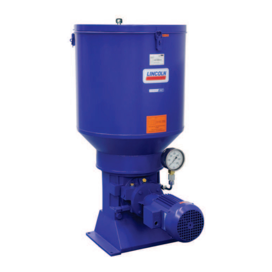
3. Overview, functional description 3.1 Overview Fig. 3 Structure of the pumps ZPU 08/14/24 1 Pump housing 7 Check valve 2 Lubricant reservoir 8 Lubricant filter 3 Stirring paddle with scraper blade and fixed paddle 9 Pressure gauge 4 High-pressure pump element... -
Page 14: Accessories
The pressure sensor monitors the delivery pressure of the Reservoir pump. The pressure sensor has digital and analog outputs, and The reservoir stores the lubricant. Different reservoir designs also an IO-Link interface for connection to the system control. and reservoir sizes exist in accordance with the pump variant. The switching points can be set to anywhere in the range from Reservoir cover 0 to 400 bar. - Page 15 Functional description of high-pressure pump element for • Delivery piston 1 shifts the floating control piston 3 up with pumps ZPU08, ZPU14, ZPU24 the lubricant in front of it (from the preceding suction stroke). The pump element (Fig. 3/4) works as a piston pump with two •...
-
Page 16: Technical Data
4. Technical data 4.1 Pump ZPU 08 … 24 Table 4 Technical data of the pump Parameter ZPU 08 ZPU 14 ZPU 24 Delivery rate 8000 cm³/h [488 in³/h] 14000 cm³/h [855 in³/h] 24000 cm³/h [1465 in³/h] Operating pressure max. 400 bar [5800 psi] max. -
Page 17: Drive Motors
4.2 Drive motors 4.2.1 Multi-voltage motors Table 5 Technical data for multi-voltage motors Parameter ZPU 08 ZPU 14 ZPU 24 Manufacturer Motor type G80F/4D71C-4 G80F/4D80E-4 G90F/4D90LD-4 Item number 245-13575-1 245-13575-2 2450-00000026 Operating mode Switching type Frequency f [Hz] Rated capacity P [kW] 0.37... -
Page 18: Motors 290 / 500 V (50Hz)
4.2.2 Motors 290 / 500 V (50Hz) Table 6 Technical data for motors with 290/500 V (50 Hz) Parameter ZPU 08 ZPU 14 ZPU 24 Manufacturer Motor type G80F/D71B-4 G80F/3D71C-4 G90F/3D71C-4 Item number 245-13564-1 245-13564-2 2450-00000046 Frequency f [Hz] Rated capacity P [kW] 0.37... -
Page 19: Pressure Monitor
4.3 Pressure monitor Table 7 Fig. 9 Technical data for pressure monitors Parameter Pressure range Pressure range 160 to 400 bar 75 to 170 bar <Co ntent> Piston and cylinder 7 mm 10 mm diameter Pressure spring 4 mm 4 mm Item no. -
Page 20: Pressure Sensor
4.4 Pressure sensor Fig. 10 Table 8 Pin assignment of M12 port Signal Power + Out 2 PNP/NPN 4…20 mA/0…10 V (selectable) Power - Out 1 PNP/NPN/IO-Link (selectable) Pressure sensor 2340-00000108: dimensions and connection diagram NOTE For detailed information on installing and operating the pressure sensor, see the corresponding operating instructions 951-181-028 Table 9 Technical data for pressure sensor 2340-00000108... -
Page 21: Ultrasonic Sensor 664-853Xx-X
4.5 Ultrasonic sensor 664-853xx-x Table 10 Technical data Parameter Value Blind zone 0-65 mm Sensing range 600 mm Ultrasonic frequency approx. 400 kHz Sonic frequency 3.7 Hz Resolution 0.18 mm Accuracy ± 1 % Reproducibility ± 15 % Sensing range in centimeters The dark gray areas (A) indicate the range in which the normal reflector (conduit) is reliably detected. - Page 22 Table 11 Electrical connection Color (IEC 60757) Brown (BN) Blue (BU) Black (BK) White (WH) D3 / Com Gray (GY) Table 12 Display of the circuit states Parameter Switching points Display of the LEDs D1 (up D2 (up to 10/21) (from 10/21) to 10/21) (from 10/21)
-
Page 23: Switching Points Of Ultrasonic Sensor For Reservoir Design Xybu
4.5.1 Switching points of ultrasonic sensor Table 13 for reservoir design XYBU Switching points Fig. 12 Reservoir size D1 Full D2 Low-level D3 Pre-empty liters [gal.] signal <Co ntent> [10.6] [26.4] Switching points of ultrasonic sensor... -
Page 24: Analog Ultrasonic Sensor
4.6 Analog ultrasonic sensor Fig. 13 237-11204-4 237-11204-5 Sensing range: The light gray area (B) represents the range in which a large reflector (such as the lubricant) is still detected. No evaluation is possible outside the light gray area. Dimensions, connection diagram, and sensing ranges Table 14 Technical data Order number... -
Page 25: Measuring Range Of Analog Ultrasonic Sensor For Reservoir Design Xybu
4.6.1 Measuring range of analog ultrasonic sensor for reservoir design XYBU Fig. 14 Measuring range of ultrasonic sensor Table 15 Measuring range Reservoir size D1 Full (20 mA) D2 Low-level (4 mA) liters [gal.] <Co ntent> [10.6] [26.4]... -
Page 26: Pump Type Identification Code Zpu 08
4.7 Pump type identification code ZPU 08…24 4.7.1 Basic parameters and reservoir version ZPU 0 8 G X - 100 XYBU - 380-415 / 420-480 - DW Type designation: Centralized lubrication pump Flow rate: 8000 cm³/h [488 in³/h] 14000 cm³/h [855 in³/h] 24000 cm³/h [1465 in³/h]... -
Page 27: Delivery, Returns, Storage
5.5 Storage conditions for products filled 5. Delivery, returns, storage with lubricant 5.1 Delivery For products filled with lubricant, the permitted storage temperature range is: After receipt of the shipment, it must be inspected for any minimum + 5 °C [+41 °F] shipping damage and for completeness according to the maximum... -
Page 28: Assembly
Observe the following points for internal transportation of the pump: • SKF recommends that the customer use a height-adjustable pallet jack or a forklift for transport to the installation or storage location. • During transportation, use at least two ratchet straps to secure the pump against the tipping over. -
Page 29: Dimensions
(+ 40 mm) must be observed. 6.4.1 ZPU xx G – with geared flange-mounted motor Fig. 17 Dimensions (mm) of ZPU 08/14/24 with geared flange-mounted motor 1 Connection of pressure line, G 3/4“ Connection of filling line, G 3/4“ 2 Connection of return line, G 3/4“... -
Page 30: Zpu Xx F - With Free Shaft Extension
6.4.2 ZPU xx F – with free shaft extension Fig. 18 Dimensions (mm) of ZPU 08/14/24 with free shaft extension 1 Connection of pressure line, G 3/4“ 3 Connection of filling line, G 3/4“ 2 Connection of return line, G 3/4“... -
Page 31: Zpu 08 S F - With Flanged Worm Drive I=20:1 And Free Shaft Extension
6.4.3 ZPU 08 S F – with flanged worm drive i=20:1 and free shaft extension Fig. 19 Dimensions (mm) ZPU 08 S with flanged worm drive 1 Connection of pressure line, G 3/4“ 3 Connection of filling line, G 3/4“... -
Page 32: Zpu 08 S - With Flanged Worm Drive I=20:1 And Three-Phase Flange-Mounted Motor
6.4.4 ZPU 08 S – with flanged worm drive i=20:1 and three-phase flange-mounted motor Fig. 20 Dimensions (mm) ZPU 08 S with flanged worm drive 1 Connection of pressure line, G 3/4“ 3 Connection of filling line, G 3/4“ 2 Connection of return line, G 3/4“... -
Page 33: Filling With Lubricant
6.5 Filling with lubricant < WARNING 6.5.1 Filling via the reservoir cover Crushing hazard Crushing hazard on the rotating stirring paddle. Fig. 21 Filling through the opening of the reservoir cover is permitted only if the pump has first been disconnected from the power supply. -
Page 34: Filling Via The Fill Connection
6.5.2 Filling via the fill connection 6.6 Electrical connection Fig. 22 < WARNING Electric shock Work on electrical components may be performed only by qualified electricians. At a minimum, the following safety measures must be taken before any work on electrical components is done: •... -
Page 35: Bleeding The Pump
Observe the following assembly information for safe and 6.7 Bleeding the pump trouble-free operation: • Generally valid regulations and company regulations Before connecting the lubricant line, the pump must be bled. regarding the laying of pressurized pipe and hose lines must To do this, switch on the pump (the direction of rotation of the be observed. -
Page 36: First Start-Up
Lubricant is fed without bubbles. The bearings and friction points requiring lubrication receive the planned lubricant volume. 7.3 Activating the pump Activate the pump by: – Switching on the machine contact – Using your own control unit (supplied by customer, not by SKF) -
Page 37: Operation
8.1 Operating the pump 8. Operation The pump is operated via the control of the centralized SKF products operate largely automatically. lubrication system. For information on pump operation, see the The activities required during normal operation are limited system documentation for the centralized lubrication system. -
Page 38: Maintenance Of The Pump
9.1.2 Replacing the check valve 9.1 Maintenance of the pump Fig. 24 < WARNING Risk of electric shock/injury At a minimum, the following safety measures must be taken before any work on the pump is done: • Unauthorized persons must be kept away •... -
Page 39: Maintenance Of The Motor
9.3 Maintenance of the motor < WARNING Risk of electric shock/injury At a minimum, the following safety measures must be taken before any work on the motor is done: • Unauthorized persons must be kept away • Mark and secure the work area •... -
Page 40: Cleaning
< 10. Cleaning WARNING Risk of fatal electric shock 10.1 Basics Cleaning should be carried out in accordance with the operator's Cleaning work may only be performed on own company rules, and cleaning agents and devices and the products that have been de-energized first. When personal protective equipment to be used should likewise be cleaning electrical components, be mindful of the selected in accordance with those rules. -
Page 41: Faults, Causes, And Remedies
11. Faults, causes, and remedies Table 19 Fault table Fault Possible cause Remedy Pump does not deliver • Reservoir empty • Fill the reservoir with clean lubricant. medium • Then run the pump until lubricant comes out of the pressure line connection without bubbles. •... -
Page 42: Shutdown, Disposal
12. Shutdown, disposal 12.1 Temporary shutdown Temporary shutdowns should be done by a course of action to be defined by the operator. 12.2 Permanent shutdown, disassembly Permanent shutdown and disassembly of the product must be planned properly by the operator and conducted in compliance with all applicable laws and regulations. -
Page 43: Spare Parts
13. Spare parts Spare parts may be used exclusively for replacement of identical defective parts. Modifications with spare parts on existing products are not allowed. 13.1 Pump Table 20 Spare parts ZPU08 … 24 Designation Pcs. Item number Repair kit for pump element 505-30922-1 Check valve with seals 505-36089-1... -
Page 44: Assembly Groups For The Drive Of The Pump
13.3.1 Drive with geared motor Table 23 Geared motors No. Description Pcs. Item number Figure (example) Geared flange-mounted motor ZPU 08 • 0.37 kW, 380-415V/50Hz, 60 rpm, 245-13575-1 420-480V/60Hz, 72 rpm • 0.37 kW, 500V/50Hz, 60 rpm 245-13564-1 Geared flange-mounted motor ZPU 14 •... -
Page 45: Drive With Worm Drive And Free Shaft Extension
13.3.3 Drive with worm drive and free shaft extension Table 25 Worm drive with free shaft extension No. Description Pcs. Item number Figure Worm drive 20 : 1 246-14422-2 Washer ST 8 CF 209-13077-1 Hexagon head screw M8 x 30 CF 200-12007-6 13.3.4 Rotary drive with free shaft extension Table 26... -
Page 46: Pressure Sensor Assy
13.5 Pressure sensor assy Designation Pcs. Item number Figure Pressure sensor assy 2340-00000108 Including separate adapter G1/4 to EN 2852 and M12 coupling socket, 5-pin, A-coded 90°... -
Page 47: Appendix
14. Appendix 14.1 China RoHS Table Table 28... - Page 48 ® SKF and Lincoln are registered trademarks of the SKF Group. ™ eLube is a trademark of the SKF Group. © SKF Group 2023 Reprint or reproduction of the contents of this information - even in part - is permitted only with SKF's prior written consent.
Need help?
Do you have a question about the ZPU 08 and is the answer not in the manual?
Questions and answers