Table of Contents
Advertisement
Quick Links
Advertisement
Table of Contents
Troubleshooting

Related Manuals for Sullair 3007


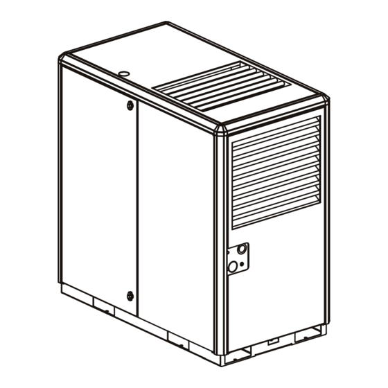
Summary of Contents for Sullair 3007
- Page 1 SULL AIR ® ® NDUSTRIAL OMPRESSOR 3000, 3700, 4500, 3000 , 3700 , 4500 30, 37 & 45 /40, 50 & 60HP Air-Cooled Standard & 24 KT PART NUMBER: 02250155-601 KEEP FOR FUTURE REFERENCE © SULLAIR CORPORATION Starting Serial Number: 003-139556...
- Page 2 Sullair Air Care Seminars are courses that provide hands-on instruction in the proper operation, maintenance and service of Sullair equipment. Individual seminars on Industrial compressors and compressor electrical systems are presented at regular intervals throughout the year at a dedicated training facility at Sullair's corporate headquarters in Michigan City, Indiana.
-
Page 3: Table Of Contents
Entrapment..................5 2 - DESCRIPTION..................7 Introduction..................7 Description of Components ..............8 Sullair Compressor Unit, Functional Description......... 8 Compressor Cooling and Lubrication System, Functional Description ..................10 Compressor Discharge System, Functional Description ....10 Control System, Functional Description ..........11 START MODE - 0 TO 50 PSIG (0 TO 3.5 BAR)................ - Page 4 Application Guide ................17 Lubrication Change Recommendations and Maintenance - Fluid Filter and Separator..............18 4 - INSTALLATION................. 25 Mounting of Compressor ..............25 Ventilation and Cooling ..............25 Air-Cooled Compressors ............. 25 Service Air Piping ................26 Pipe Sizing .................. 26 Use of Auxiliary Receiver / Sump..........
- Page 5 TABLE OF CONTENTS 7 - PARTS LISTS..................41 Procedure For Ordering Parts ............41 Recommended Spare Parts List ............43 Compressor, Frame and Drive - 3000 and 3700 Models ....44 Compressor, Frame and Drive - 4500 Model ........46 Air Inlet System .................
- Page 6 This Page Intentionally Left Blank SULL AIR 3700 Operator’s Manual and Parts List ® ®...
-
Page 7: Safety
SU_0000005 behind these statements are generally applicable to all compressors. 1.1 GENERAL Sullair Corporation and its subsidiaries design and 1.2 PERSONAL PROTECTIVE manufacture all of their products so they can be EQUIPMENT operated safely. However, the responsibility for safe... -
Page 8: Pressure Release
SECTION 1 1.3 PRESSURE RELEASE K. DO NOT engage in horseplay with air hoses as death or serious injury may result. A. Install an appropriate flow-limiting valve between the service air outlet and the shut-off (throttle) 1.4 FIRE AND EXPLOSION valve, either at the compressor or at any other A. -
Page 9: Moving Parts
SAFETY K. DO NOT attempt to operate the compressor in A DANGER any classification of hazardous environment unless the compressor has been specially designed and manufactured for that duty. 1.5 MOVING PARTS A. Keep hands, arms and other parts of the body and also clothing away from couplings, fans and INHALATION HAZARD! other moving parts. -
Page 10: Electrical Shock
SECTION 1 I. The antifreeze compound used in air line A DANGER antifreeze systems contains methanol and is toxic, harmful or fatal if swallowed. Avoid contact All field equipment must be tested for with the skin or eyes and avoid breathing the electrostatic fields prior to servicing or fumes. -
Page 11: Entrapment
SAFETY K. When moving the compressor by forklift truck, utilize fork pockets if provided. Otherwise, utilize pallet if provided. If neither fork pockets or pallet are provided, then make sure compressor is secure and well balanced on forks before attempting to raise or transport it any significant distance. - Page 12 SECTION 1 This Page Intentionally Left Blank SULL AIR 3700 Operator’s Manual and Parts List ® ®...
-
Page 13: Description
3700 Operator’s Manual and Parts List Section 2 DESCRIPTION 2.1 INTRODUCTION Compared to other types of compressors, the Sullair rotary screw is unique in mechanical reliability, with “no Your new Sullair flood-lubricated rotary screw air wear” and “no inspection” required of the working parts compressor will provide you with a unique experience in within the compressor unit. -
Page 14: Description Of Components
SECTION 2 2.2 DESCRIPTION OF COMPONENTS Sullair recommends that a 24KT sample be taken at the first filter change and sent to the factory for analysis. Refer to Figure 2-1 and Figure 2-2. The components This is a free service. The sample kit with instructions and assemblies of the air compressor are clearly shown. - Page 15 DESCRIPTION Figure 2-2 COOLING / LUBRICATION SYSTEM DISCHARGE SYSTEM SA_0000009 Figure 2-2 Air-Cooled Cooling/Lubrication and Discharge System SULL AIR 3700 Operator’s Manual and Parts List ® ®...
-
Page 16: Compressor Cooling And Lubrication System, Functional Description
SECTION 2 2.4 COMPRESSOR COOLING AND The compressed air/fluid mixture enters the receiver and flows through an internal baffle system. The direction of LUBRICATION SYSTEM, movement is changed and its velocity significantly FUNCTIONAL DESCRIPTION reduced, thus causing large droplets of fluid to form and Refer to Figure 2-2. -
Page 17: Control System, Functional Description
DESCRIPTION 2.6 CONTROL SYSTEM, FUNCTIONAL START MODE - 0 TO 50 PSIG DESCRIPTION (0 TO 3.5 BAR) Refer to Figure 2-3. The purpose of the compressor When the compressor “ ” (START) pad is depressed, Control System is to regulate the amount of air being the sump pressure will quickly rise from 0 to 50 psig (0 - compressed to match the amount of compressed air 3.4 bar). -
Page 18: Full Load Mode - 50 To 100 Psig (3.4 To 6.9 Bar)
SECTION 2 Figure 2-4 Air Outlet Blowdown Valve Pressure Regulator Minimum Pressure / Check Valve Solenoid Valve Sump Tank Air Inlet Figure 2-4 Sequencing Control System FULL LOAD MODE - 50 TO 100 PSIG (3.4 TO MODULATING MODE - 100 TO 110 PSIG (6.9 6.9 BAR) TO 7.6 BAR) When the compressed air pressure rises above 50 psig... -
Page 19: Unload Mode - In Excess Of 110 Psig (7.6 Bar)
DESCRIPTION 2.7 AIR INLET SYSTEM, FUNCTIONAL The integrated inlet valve has an orifice which vents a small amount of air inlet when the pressure regulator DESCRIPTION controls the inlet control valve. The orifice also bleeds Refer to Figure 2-5. The Compressor Inlet System any accumulated moisture from the control lines. - Page 20 SECTION 2 Figure 2-5 Air Inlet Filter Compressor Unit Air Inlet Sump Tank (Mounting) Figure 2-5 Air Inlet System SULL AIR 3700 Operator’s Manual and Parts List ® ®...
-
Page 21: Specifications
09 - 125 psig (8.6 bar) 12 - 175 psig (12 bar) Maximum pressure is rated pressure plus 10 psig (0.7 bar). NOTE For latest sound test data, consult Sullair Factory. SU_0000040 SULL AIR 3700 Operator’s Manual and Parts List ®... - Page 22 1765 RPM (60 Hz) or 1475 RPM (50 Hz) (IV) Multi-frequency and voltage motors are used. The compressors must be used only with the specified electrical frequency and voltage. NOTE For latest sound test data, consult Sullair Factory. SU_0000040 SULL AIR 3700 Operator’s Manual and Parts List...
-
Page 23: Lubrication Guide
Operator’s Manual. 3.3 APPLICATION GUIDE DO NOT MIX DIFFERENT TYPES OF FLUIDS. Sullair encourages the user to participate in a fluid Contamination of non-detergent mineral fluids with analysis program with the fluid suppliers. This could... -
Page 24: Lubrication Change Recommendations And Maintenance - Fluid Filter And Separator
SECTION 3 3.4 LUBRICATION CHANGE RECOMMENDATIONS AND MAINTENANCE - FLUID FILTER AND SEPARATOR LUBRICANT FLUID CHANGE FLUID FILTER CHANGE SEPARATOR CHANGE Sullube A, E G, C A, D SFR 1/4000 B, E G, C B, D 24KT F, E G, C A, D CP-4600-32-F B, E... - Page 25 SPECIFICATIONS Figure 3-2 Alternate Incoming Power Supply Location Air Inlet Controller Containment Pan Drain E-Stop Incoming Customer Power Supply Location Oil Level Sight Glass Moisture Drain Connection Air Exhaust 10. Air Outlet Connection Figure 3-2 Identification, Air-Cooled SULL AIR 3700 Operator’s Manual and Parts List ®...
- Page 26 SECTION 3 Figure 3-3 Figure 3-3 Piping and Instrumentation, Air-Cooled SULL AIR 3700 Operator’s Manual and Parts List ® ®...
- Page 27 SPECIFICATIONS Piping and Instrumentation, Air-Cooled Key Number Description Part Number Quantity filter, air 9" plastic 02250127-683 indicator, restriction 250003-869 inlet compressor unit motor filter, coreless 1-1/16 sae 02250155-708 cooler, air/oil 60hp 02250152-862 • cooler, air/oil 50hp 02250151-493 valve, thermal 210deg 1-1/2"-18 02250148-796 •...
- Page 28 SECTION 3 Figure 3-4 Figure 3-4 Wiring Diagram - MFV SULL AIR 3700 Operator’s Manual and Parts List ® ®...
- Page 29 SPECIFICATIONS Figure 3-5 Figure 3-5 Wiring Diagram - Wye-Delta SULL AIR 3700 Operator’s Manual and Parts List ® ®...
- Page 30 SECTION 3 Figure 3-6 Figure 3-6 Wiring Diagram - VSD SULL AIR 3700 Operator’s Manual and Parts List ® ®...
-
Page 31: Installation
SULL AIR ® ® 3700 Operator’s Manual and Parts List Section 4 INSTALLATION 4.1 MOUNTING OF COMPRESSOR 4.2 VENTILATION AND COOLING A suitable foundation or fabricated support must be AIR-COOLED COMPRESSORS established to support the compressor. It should be rigid •... -
Page 32: Service Air Piping
SECTION 4 OUTDOOR INSTALLATION (SHELTERED) NOTE Many times a compressor must be installed outside due to available space or other jobsite conditions. When this Discharged air contains a very small amount of compressor lubricating oil, and is necessary, there are certain items that should be care should be taken to ensure that this incorporated into the system to help ensure trouble-free oil would not interfere with downstream... -
Page 33: Fluid Containment
INSTALLATION 4.6 ELECTRICAL PREPARATION FLUID CONTAINMENT Compressors are equipped with a fluid containment pan Interior electrical wiring is performed at the factory. to catch any fluid in the event of a leak or spill. The drain Required customer wiring should be done by a qualified for the pan is located on the air intake end of the electrician in compliance with OSHA, National Electrical machine. -
Page 34: Motor Rotation Direction Check
SECTION 4 4.8 FAN MOTOR ROTATION CHECK A DANGER On initial start-up check that the fan is rotating in the proper direction. The correct rotation is counterclockwise Lethal shock hazards exist inside. Disconnect all power at source and lock when viewing the fan motor from the driveshaft end. out before opening or servicing. -
Page 35: Ws Controller
SULL AIR ® ® 3700 Operator’s Manual and Parts List Section 5 WS CONTROLLER 5.1 CONTROLLER LAYOUT Figure 5-1 Maintenance Indicator Fault Indicator LED Display Up Key Power Indicator Down Key Auto Mode 10. Return Key Figure 5-1 WS Controller 5.2 CONTROLLER KEYPAD 5.3 LED DISPLAY The WS controller keypad has two main pads for... - Page 36 SECTION 5 Figure 5-2 Figure 5-6 SA_0000005 SA_0000003 Figure 5-2 Figure 5-6 (Figures 5-2 and 5-3) The lower line is occasionally (Figure 5-7) When you continue beyond the status interrupted to descibe the compressor package’s information, the display will show a list of control operating state.
-
Page 37: Led Lights
WS CONTROLLER The list of displays may be navigated from either direction by using the Up “ ” or Down “ ” arrow keys. For example, to change language from normal view, press the Up arrow pad once, press the Enter key “... - Page 38 SECTION 5 This Page Intentionally Left Blank SULL AIR 3700 Operator’s Manual and Parts List ® ®...
-
Page 39: Maintenance
SULL AIR ® ® 3700 Operator’s Manual and Parts List Section 6 MAINTENANCE 6.1 GENERAL After a routine start has been made, observe the controller display and be sure it monitors the correct As you proceed in reading this section, it will be easy to readings for their particular phase of operation. -
Page 40: Fluid Maintenance
SECTION 6 FLUID FILTER ELEMENT REPLACEMENT Figure 6-1 Refer to Figure 6-1. 1. Using a wrench, remove the filter canister. 2. Remove and dispose of filter element. Observe all laws and regulations for filter disposal. 3. Clean gasket seating surface. 4. -
Page 41: Air Filter Element Replacement
MAINTENANCE AIR FILTER ELEMENT REPLACEMENT Figure 6-3 1. Clean exterior of air filter housing. 2. Rotate end cover counterclockwise and remove 3. Remove air filter element by pulling it out of the housing. 4. Clean interior of housing using a damp cloth. DO NOT blow dirt out with compressed air. -
Page 42: Pressure Regulator Adjustment
SECTION 6 PRESSURE REGULATOR ADJUSTMENT Figure 6-4 Start the compressor and adjust the service valve to maintain service air pressure approximately at 5 psi over rated pressure. Turn the inlet valve regulator adjusting screw until air just begins to escape from the control air orifice (located at the bottom of the regulator;... -
Page 43: Shaft Coupling Maintenance
3. Check for parts damaged by heat or an electrical short circuit, usually apparent by discoloration or a burnt odor. Should your problem persist after making the recommended check, consult your nearest Sullair representative. SULL AIR 3700 Operator’s Manual and Parts List ®... -
Page 44: Troubleshooting Guide
SECTION 6 6.10 TROUBLESHOOTING GUIDE SYMPTOM PROBABLE CAUSE REMEDY COMPRESSOR WILL NOT START Main Disconnect Switch Open Close switch. Line Fuse Blown Replace fuse. Motor Starter Overload Tripped Reset. Should trouble persist, check whether motor starter contacts are functioning properly. Low Incoming Line Voltage Check voltage. - Page 45 MAINTENANCE SYMPTOM PROBABLE CAUSE REMEDY COMPRESSOR WILL NOT BUILD FULL Air Demand is Too Great Check service lines for leaks or open DISCHARGE PRESSURE valves up. Dirty Air Filter Check the filter indicator and inspect and/or change element if required. Inlet Valve Bleed Orifice Plugged Insure control line bleed orifice located in assembly on top of air end is not plugged.
- Page 46 SECTION 6 SYMPTOM PROBABLE CAUSE REMEDY LIQUID WATER IN COMPRESSED AIR Plugged Strainer in Moisture Drain Line Clean and service strainer located in the LINES line off the bottom of the water separator. Water Vapor Condensation from Cooling Remove the water vapor from and Compression Occurs Naturally compressed air prior to distribution through the air system.
-
Page 47: Parts Lists
PARTS LISTS 7.1 PROCEDURE FOR ORDERING PARTS Parts should be ordered from the nearest Sullair Representative or the Representative from whom the compressor was purchased. If for any reason parts cannot be obtained in this manner, contact the factory directly at the addresses, phone or fax numbers listed below. - Page 48 SECTION 7 This Page Intentionally Left Blank SULL AIR 3700 Operator’s Manual and Parts List ® ®...
-
Page 49: Recommended Spare Parts List
PARTS LISTS 7.2 RECOMMENDED SPARE PARTS LIST List Description Part Number Quantity ELEMENTS element, compressor fluid filter 02250155-708 02250155-709 element, heavy duty air filter 02250127-683 02250127-684 element, heavy duty air filter 02250091-634 02250131-499 element, replacement for separator 02250160-774 02250160-776 KITS kit, repair for minimum pressurelcheck valve 02250097-598 02250110-727 kit, cap for minimum pressurelcheck valve 02250097-598... -
Page 50: Compressor, Frame And Drive - 3000 And 3700 Models
SECTION 7 7.3 COMPRESSOR, FRAME AND DRIVE - 3000 AND 3700 MODELS Figure 7-2 02250 152-458r00 A. From Air Inlet Filter B. Oil Return From Sightglass on Receiver Tank C. To Receiver Tank D. From Blowdown Valve E. Main Oil Connection SULL AIR 3700 Operator’s Manual and Parts List ®... - Page 51 The shaft seal is not considered part of the compressor unit in regard to the two year warranty, but the normal Sullair parts warranty does apply. For shaft seal repairs, order repair kit No. 02250050-363 and installation kit No. 602542-001.
-
Page 52: Compressor, Frame And Drive - 4500 Model
SECTION 7 7.4 COMPRESSOR, FRAME AND DRIVE - 4500 MODEL Figure 7-3 18 19 02250 153-265r00 A. From Air Inlet Filter B. Oil Return From Sightglass on Receiver Tank C. To Receiver Tank D. From Blowdown Valve E. Main Oil Connection SULL AIR 3700 Operator’s Manual and Parts List ®... - Page 53 The shaft seal is not considered part of the compressor unit in regard to the two year warranty, but the normal Sullair parts warranty does apply. For shaft seal repairs, order repair kit No. 02250050-363 and installation kit No. 602542-001.
-
Page 54: Air Inlet System
SECTION 7 7.5 AIR INLET SYSTEM Figure 7-4 02250 152-457r00 A. To Air Inlet on Compressor Unit SULL AIR 3700 Operator’s Manual and Parts List ® ®... - Page 55 PARTS LISTS Air Inlet System (Continued) Key Number Description Part Number Quantity clamp, t-bolt ss band 4.50" id 02250084-842 filter, air 9" (I) 02250127-683 hose, rubber el 120deg 4" inl ws37 02250156-927 indicator, restriction 20" h20 250003-869 nut, serr flng m8 x 1.25 882508-125 screw, hex serr washer m8 x 25 882608-025...
-
Page 56: Air Piping - Air-Cooled
SECTION 7 7.6 AIR PIPING - AIR-COOLED Figure 7-5 02250 152-474r00 A. To After-Cooler B. From After-Cooler C. From Minimum Pressure Valve SULL AIR 3700 Operator’s Manual and Parts List ® ®... - Page 57 PARTS LISTS Air Piping - Air-Cooled (Continued) Key Number Description Part Number Quantity tube, mpv/clr/moist sep ls12 02250121-707 separator, water d-h 1-1/2" fnpt 1/4" drn (I) 02250144-635 support, outlet conn 1-1/2npt 02250152-215 tube, mpv to a/c 1.5" orfs 3700 02250157-836 tube, a/c to trap 1.5"...
-
Page 58: Fluid Piping - Air-Cooled
SECTION 7 7.7 FLUID PIPING - AIR-COOLED Figure 7-6 02250152-488r00 A. To Cooler B. To Compressor Unit C. To Receiver Tank SULL AIR 3700 Operator’s Manual and Parts List ® ®... - Page 59 (II) – (I) For maintenance on coreless filter No. 02250155-708, order replacement element No. 02250155-709. (II) This part may vary per machine specification. Consult the Sullair factory for details. SULL AIR 3700 Operator’s Manual and Parts List ®...
-
Page 60: Cooling And Lubrication System - Air-Cooled 18"/60Hz Fan, Standard Cooler
SECTION 7 7.8 COOLING AND LUBRICATION SYSTEM - AIR-COOLED 18"/60HZ FAN, STANDARD COOLER Figure 7-7 02250158-442-R01 A. In from MPV B. Out to Water Separator C. Thermal Bypass Valve D. Cooler Pack Assembly Rests on Top Rails of Canopy. Thread Forming Screws Attach Cooler Pack to Rails. - Page 61 PARTS LISTS Cooling and Lubrication System - Air-Cooled 18"/60Hz Fan, Standard Cooler (Continued) Key Number Description Part Number Quantity cooler, air/oil 50hp 02250151-493 • cooler, air oil high capacity/60HP 02250152-862 duct, centrifugal fan 50hp 02250151-496 support, fan motor 50hp 02250151-501 panel, venturi 50hp 18"...
-
Page 62: Discharge, Sump And Piping System
SECTION 7 7.9 DISCHARGE, SUMP AND PIPING SYSTEM Figure 7-8 A. To Strainer on Solenoid Valve Assembly B. To After-Cooler In C. To Unit Oil Return Port D. From Unit Discharge E. To Grounding Location on Frame F. To Frame SULL AIR 3700 Operator’s Manual and Parts List ®... - Page 63 PARTS LISTS Discharge, Sump and Piping System (Continued) Key Number Description Part Number Quantity adapter, sae 1 7/8-12 x 1 7/8-12 02250055-014 vlv. min press chk 1-7/8 sae 0-ring por (I) 02250097-598 plug,sight glass 1 5/16" sae 02250097-610 elb, 90 deg 3/4 sae x 3/8 nptf 02250100-093 adapter, sae 7/16 x 7/16-20 02250101-783...
-
Page 64: Moisture Drain
SECTION 7 7.10 MOISTURE DRAIN Figure 7-9 02250 152-494r00 A. Condensate Drain To Air Out Bracket B. To Water Separator at Bottom of Bowl C. To Bottom of Starter Box SULL AIR 3700 Operator’s Manual and Parts List ® ®... - Page 65 PARTS LISTS Moisture Drain (Continued) Key Number Description Part Number Quantity locknut, n4 conduit sealing 02250071-362 valve, solenoid 2wnc 1/4 200# 24vdc (I) 02250155-715 valve, ball 1/4" npt 047115 strainer, v-type 300psix1/4 (II) 241771 nipple, conduit 1/2 x 1.5” 250007-169 elbow, 90deg m swvl 1/4t x 1/4 npt 250025-850 connector, male1/4tube x 1/4...
-
Page 66: Pneumatic Control System - Standard
SECTION 7 7.11 PNEUMATIC CONTROL SYSTEM - STANDARD Figure 7-10 02250152-594-R02 A. Port 1 D. To Starter Box B. Port 2 E. To Inlet Valve C. Port 3 F. To Inlet Adapter SULL AIR 3700 Operator’s Manual and Parts List ®... - Page 67 PARTS LISTS G. To Receiver Tank H. To Minimum Pressure Valve SULL AIR 3700 Operator’s Manual and Parts List ® ®...
-
Page 68: Pneumatic Control System - With Sequencing
SECTION 7 7.12 PNEUMATIC CONTROL SYSTEM - WITH SEQUENCING Figure 7-11 02250163-528R00 A. Port 1 E. To Inlet Valve B. Port 2 F. To Inlet Adapter C. Port 3 G. To Receiver Tank D. To Starter Box H. To Stator Below Inlet SULL AIR 3700 Operator’s Manual and Parts List ®... - Page 69 PARTS LISTS 7.12 Pneumatic Control System - With Sequencing (Continued) Key Number Description Part Number Quantity locknut, n4 conduit sealing 02250071-362 valve, 1/2 bldwn 1.8:1 250 psig 02250100-042 valve, check 1/4" poppet style 02250115-272 valve, solenoid 3wno 1/4 250# 24vdc 02250155-714 tbg, nylon 1/4"-od red 02250155-961...
- Page 70 SECTION 7 Pneumatic Control System - With Sequencing (Continued) Key Number Description Part Number Quantity insert, nylon tubing 1/4" od 02250052-841 elbow, check valve 1/4t x 1/8p 02250058-275 locknut, n4 conduit sealing 02250071-362 valve, 1/2 bldwn 1.8:1 250 psig 02250100-042 valve, solenoid 3wno 1/4 250# 24vdc 02250155-714 tbg, nylon 1/4"...
-
Page 71: Control System And Electric Parts - 230/460 Wye-Delta
PARTS LISTS 7.13 CONTROL SYSTEM AND ELECTRIC PARTS - 230/460 WYE-DELTA Figure 7-12 02250 152-491r00 A. P1 - Wet Sump Pressure B. P2 - Line Pressure C. Solenoid 1 D. Solenoid 4 E. T1 - Wet Discharge Temp. SULL AIR 3700 Operator’s Manual and Parts List ®... - Page 72 4-1/0 849215-025 washer, nord-lock pl m8 sp 883208-166 contactor (I) – Starter – (I) This part may vary per machine specification. Consult the Sullair factory for details. SULL AIR 3700 Operator’s Manual and Parts List ® ®...
-
Page 73: Enclosure - Air-Cooled
PARTS LISTS 7.14 ENCLOSURE - AIR-COOLED Figure 7-13 02250 155-297r00 A. Fan Box SULL AIR 3700 Operator’s Manual and Parts List ® ®... - Page 74 SECTION 7 Enclosure - Air-Cooled (Continued) Key Number Description Part Number Quantity cap, molded canopy corner 50HP 02250150-893 rail, vertical 37KW 02250150-910 rail, roof air out end 37KW 02250150-912 gusset, str crnr square 37KW 02250151-177 panel, canopy door flanged w/cutout 02250151-178 panel, canopy door flanged 37KW 02250151-179...
-
Page 75: Decal Section - Air-Cooled
PARTS LISTS 7.15 DECAL SECTION - AIR-COOLED Figure 7-14 02250152-489 A. Attach to the Bottom on Inside of Starter Box B. Attach to Inside of Starter Door C. Attach to Sub-panel Inside Starter Box D. Attach to Top of Shipping Strap E. - Page 76 02250154-360 decal, remove before start-up 02250158-358 rivet, pop 1/8 x 1/2 843102-050 (I) This decal may vary per machine specification. Consult the Sullair factory for details. * Decal not shown. SULL AIR 3700 Operator’s Manual and Parts List ® ®...
- Page 77 PARTS LISTS Decal Section - Air-Cooled (Continued) 042218 SULL AIR 3700 Operator’s Manual and Parts List ® ®...
- Page 78 SECTION 7 Decal Section - Air-Cooled (Continued) SULL AIR 3700 Operator’s Manual and Parts List ® ®...
- Page 79 PARTS LISTS SULL AIR 3700 Operator’s Manual and Parts List ® ®...
- Page 80 ® ORLDWIDE ALES AND ERVICE SULLAIR ASIA, LTD. Sullair Road, No. 1 SULLAIR EUROPE, S.A. Chiwan, Shekou Zone Des Granges BP 82 Shenzhen, Guangdong PRV. 42602 Montbrison Cedex, France PRC POST CODE 518068 Telephone: 33-477968470 Telephone: 755-6851686 Fax: 33-477968499 Fax: 755-6853473 www.sullaireurope.com...
Need help?
Do you have a question about the 3007 and is the answer not in the manual?
Questions and answers