Sign In
Upload
Manuals
Brands
YOKOGAWA Manuals
Controller
Vitesse FA-M3V
YOKOGAWA Vitesse FA-M3V Manuals
Manuals and User Guides for YOKOGAWA Vitesse FA-M3V. We have
2
YOKOGAWA Vitesse FA-M3V manuals available for free PDF download: User Manual
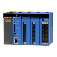
YOKOGAWA Vitesse FA-M3V User Manual (272 pages)
Brand:
YOKOGAWA
| Category:
Controller
| Size: 8 MB
Table of Contents
Applicable Product
3
Precautions
4
Introduction
12
Copyrights and Trademarks
13
Table of Contents
15
Part a Standard Version
21
IM 34M06C11-01E 36Th Edition : Feb.28
21
A1. System Configuration
23
System Configuration
23
Basic Configuration
23
Main Unit
23
Subunit
23
Slot Number
24
Example of Increasing the Number of I/O Points Using Fiber-Optic FA-Bus Type 2 Modules
25
A1.2 Restrictions on Module Installation
27
A1.2.1 Restrictions on Module Location
27
A1.2.2 Restrictions on CPU Module Installation
28
A1.2.3 Restrictions on I/O Module Installation
29
A1.2.4 Restrictions Due to Current Consumption
31
Peripheral Tools Supporting the Program Development of the FA-M3
32
A2. Specifications and Configuration
33
Specifications
33
Common Specifications
33
Power Supply Specifications
34
A2.2 FA-M3 Controller Configuration
35
A2.2.1 Components
35
Module Names
35
FA-M3 Components
35
A2.3 Power Supply Modules
45
F3PU10-0N/F3PU10-0S/F3PU20-0N/F3PU20-0S Power Supply Modules
45
F3PU30-0N/F3PU30-0S Power Supply Modules
48
F3PU16-0N/ F3PU16-0S and F3PU26-0N/ F3PU26-0S Power Supply Modules
50
F3PU36-0N/F3PU36-0S Power Supply Module
52
A2.4 Base Modules
55
A2.5 I/O Modules
56
Components and Their Functions
56
External Dimensions
56
Isolation Methods
57
Terminal Arrangement
57
External Connection
57
F3XH04-3N High-Speed Input Module
58
Setting up the Pulse-Capture and Interrupt Functions
59
F3XA08-1N/F3XA08-2N AC Input Modules
63
F3XA16-1N AC Input Module
65
F3XC08-0N No-Voltage Contact Input Module
66
F3XC08-0C No-Voltage Contact Input Module (Independent Commons)
67
F3XD08-6F DC Input Module
68
F3XD16-3F/F3XD16-4F/F3XD16-3H DC Input Modules
69
F3XD32-3F/F3XD32-4F/F3XD32-5F DC Input Modules
71
F3XD64-3F/F3XD64-4F DC Input Modules
73
F3XD08-6N DC Input Module
75
F3XD16-3N/F3XD16-4N DC-Input Modules
77
F3XD32-3N/F3XD32-4N/F3XD32-5N DC Input Modules
79
F3XD64-3N/F3XD64-4N DC Input Modules
81
F3XD64-6M DC Input Module
83
F3YD04-7N Transistor Output Module
84
F3YA08-2N Triac Output Module
85
F3YC08-0C/F3YC08-0N Relay Output Module
87
F3YD08-6A/F3YD08-6B Transistor Output Modules
90
F3YD08-7A Transistor Output Module
92
F3YD14-5A/F3YD14-5B Transistor Output Modules
94
F3YC16-0N Relay Output Module
96
F3YD32-1A/F3YD32-1B Transistor Output Modules
98
F3YD32-1H Transistor Output Module (for High Speed Output)
100
F3YD32-1P/F3YD64-1P Transistor Output Modules (with Short-Circuit Protector)
102
F3YD32-1R/F3YD64-1R Transistor Output Modules (with Short-Circuit Protector)
104
F3YD32-1T TTL Output Module
108
F3YD64-1A Transistor Output Module
110
F3YD64-1F Transistor Output Module
112
F3YD64-1M Transistor Output Module
114
F3WD64-3P/F3WD64-4P Input/Output Modules (with Short-Circuit Protector)
116
F3WD64-3F/F3WD64-4F Input/Output Modules
120
F3WD64-3N/F3WD64-4N Input/Output Modules
124
A2.6 ROM Packs
128
A2.7 Cables
130
Cables for Programming Tool
130
KM11-2N (for PC9801 (NEC))
130
KM11-2T/KM11-3T/KM11-4T (for DOS/V (IBM PC/AT Compatibles))
131
KM13-1S (USB-Serial Converter)
131
CPU Port/D-Sub 9-Pin Adapter Cable
132
Km10-0C
132
Cables for Connector Terminal Blocks
133
Km55-005, Km55-010, Km55-015, Km55-020, Km55-025, Km55-030
133
Fiber-Optic Cord
134
Km60
134
Fiber-Optic Cables
135
Km61, Km62, Km67, Km69
135
Km65
135
Monitor Cables (for F3SP08-2X, -3X, and -5X)
138
KM21-2A (D-Sub 25-Pin)
138
KM21-2B (D-Sub 9-Pin)
138
Monitor Cables (for F3SP66-4S and F3SP67-6S)
139
KM21-2T (D-Sub 9-Pin)
139
KM21-2N (D-Sub 25-Pin)
139
SIO Port/D-Sub 9-Pin Adaptor Cable (for F3SP66-4S and F3SP67-6S)
140
Km10-0S
140
A2.8 Terminal Block Unit and Connector Terminal Block
141
Ta40-0N
141
Ta50-0N/Ta50-1N/Ta50-2N
144
Ta60-0N
147
A2.9 Module Current Consumption Tables
149
A2.10 External Power Supply
153
A2.11 External Dimensions
154
A3. Installation and Wiring
159
A3.1 Environmental Conditions for Installation Within a Panel Enclosure
159
A3.2 Methods for Mounting the FA-M3 Within a Panel Enclosure
161
A3.2.2 Mounting Dimensions
162
A3.2.3 Mounting on and Removing from a DIN Rail
163
A3.2.4 Attaching/Detaching the Module
166
A3.2.5 Mounting Depth and Space
168
System Design Considerations
170
A3.3.1 Power Line Wiring and Emergency-Stop Circuit
170
A3.3.2 Grounding Lines
171
A3.3.3 Relay Circuits
172
A3.3.4 Protection against Output Short-Circuit
172
A3.3.5 Interlocking
173
A3.3.6 Measures against Power Failure
174
Noise Control Considerations
178
Wiring the Power Supply Module
180
A3.5.1 Re-Checking Specifications
180
A3.5.2 Wiring Materials
180
A3.5.3 Power Supply Wiring
181
A3.5.4 Grounding Procedure
183
Wiring I/O Modules
184
A3.6.1 Re-Checking Specifications
184
A3.6.2 Wiring Materials
184
A3.6 Wiring I/O Modules
184
A3.6.3 Terminal Blocks and Connectors
185
A3.6.4 Connecting Input Devices
187
A3.6.5 Connecting Output Devices
190
A3.7 External Cable Routing Requirements
192
A3.8 Calculating Power Consumption
193
CE Marking Conformance
194
A3.9 CE Marking Conformance
194
A3.9.1 EMC Directive
195
A3.9.2 Low Voltage Directive
203
A4. Test Runs and Troubleshooting
207
A4.1 Test Run Procedure
207
A4.2 Test Run Precautions
208
Self-Diagnostic Functions
209
A4.3.1 CPU Module Operation at Power-On
209
A4.3.2 Fault Identification
211
A4.3.3 Indicating Problem Severity and Status of Output Module
212
A4.4 Troubleshooting Procedure
215
A4.5 CPU Module Reset and Memory Clearance
216
A5. Maintenance and Inspection
219
A5.1 Replacing Modules
219
A5.2 Routine Inspection
220
Appendix A1 System-Wide Restrictions on
221
Module Installation
221
Appendix A1.1
221
Checking Compliance with Restrictions on Module Installation
221
Appendix A1.2 Restrictions Due to the Number of Slots
225
Appendix A1.3 Restrictions Due to the Size of Data Area
226
Appendix A1.4
228
Restrictions Due to the Type of CPU Module
228
Appendix A1.4.2 for BASIC CPU Module Type
229
Appendix A2
229
General
231
User's Manuals and Approved / Compliant Modules
231
Part B FA-M3 Value (F3SC21-1N)
239
B1. System Configuration
241
B1.1 System Configuration
241
B1.2 Restrictions on Module Installation
243
B1.2.1 Restrictions on Module Location
243
B1.2.2 Restrictions Due to Current Consumption
243
B1.3 Peripheral Tools Supporting the Program Development of FA-M3
244
B2.1 Specifications
245
B2. Specifications and Configuration
245
B2.2 System Configuration
246
B2.2.1 Components
246
B2.3 Sequence CPU Module
247
B2.3.1 Overview
247
B2.3.2 Power Supply Block of F3SP05-0P Module
247
B2.3.3 External Dimensions
249
Part C FA-M3 Value II (F3SC22-□□, F3SC23-□□)
251
C1.1 System Configuration
253
C1.2 Restrictions on Module Installation
255
C1.2.1 Restrictions on Module Location
255
C1.2.2 Restrictions Due to Current Consumption
255
C1.3 Peripheral Tools Supporting the Program Development of FA-M3
256
C2.1 Specifications
257
C2. Specifications and Configuration
257
C2.2 System Configuration
258
C2.2.1 Components
258
C2.3 Sequence CPU Module
259
C2.3.1 Overview
259
C2.3.2
259
Power Supply Block of F3SP08-0P and F3SP08-SP Module C2-3
259
C2.3.3 External Dimensions
261
C2.4 F3WD32-3F Input/Output Module
262
Index
267
Revision Information
269
Advertisement
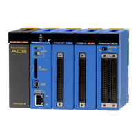
YOKOGAWA Vitesse FA-M3V User Manual (62 pages)
Brand:
YOKOGAWA
| Category:
Media Converter
| Size: 1 MB
Table of Contents
Applicable Product
3
Important
4
Introduction
12
Copyrights and Trademarks
13
Table of Contents
15
Part a KM13-1S
17
Model and Suffix Codes
21
Functional Specifications
21
Compatible Pcs and Operating Systems
21
External Dimensions
21
Precautions When Using KM13-1S
22
Serial No. of KM13-1S
22
A3. Installation
23
A3.1 Connecting the KM13-1S
23
Attaching to the PC
23
Installing in a Windows 7/8/8.1/10 Environment
24
A3.3 Installing in Windows Vista Environment
26
A3.4 Verifying Installation in a Windows Vista/7/8/8.1/10 Environment
28
A3.5 Installing in Windows XP Environment
29
A3.6 Installing in Windows 2000 Environment
31
A3.7 Verifying Installation in Windows 2000/XP Environment
33
A4. COM Port Setup
35
A4.1 COM Port Setup Using Device Manager
36
A4.1.2 Operation in Windows 2000/XP
38
A5. Uninstalling the Driver
39
A5.1 for Windows Visa/7/8/8.1/10
39
A5.2 for Windows 2000/XP
40
Index
41
Part B KM13-1N
43
B1. Features
45
B2. Specifications
47
Model and Suffix Codes
47
Functional Specifications
47
Compatible Pcs and Operating Systems
47
External Dimensions
47
Precautions When Using KM13-1N
48
Serial No. of KM13-1N
48
B3. Installation
49
B3.1 Connecting the KM13-1N
49
Attaching to the PC
49
B3.2 Installing in Windows 2000 Environment
50
B3.3 Installing in Windows XP Environment
52
B3.4 Verifying Installation in Windows 2000/XP Environment
53
B4. COM Port Setup
55
B4.1 COM Port Setup Using Device Manager
56
B5. Uninstalling the Driver
57
B5.1 for Windows 2000/XP
57
Index
59
Revision Information
61
Advertisement
Related Products
YOKOGAWA FX103
YOKOGAWA FX106
YOKOGAWA FX112
YOKOGAWA Revolution FA-M3 R
YOKOGAWA STARDOM FCN-500
YOKOGAWA FA-M3V e-RT3 Plus
YOKOGAWA FA-M3 Vitesse
YOKOGAWA FA-M3 Series
YOKOGAWA FA-M3 YHLS Master Module
YOKOGAWA FA-M3 F3YP22-0P
YOKOGAWA Categories
Measuring Instruments
Test Equipment
Transmitter
Controller
Media Converter
More YOKOGAWA Manuals
Login
Sign In
OR
Sign in with Facebook
Sign in with Google
Upload manual
Upload from disk
Upload from URL