
Related Manuals for YOKOGAWA UT75A


Summary of Contents for YOKOGAWA UT75A
- Page 1 User’s Manual UT75A Digital Indicating Controller User’s Manual IM 05P01B41-01EN IM 05P01B41-01EN 3rd Edition...
- Page 2 Product Registration Thank you for purchasing YOKOGAWA products. YOKOGAWA provides registered users with a variety of information and services. Please allow us to serve you best by completing the product registration form accessible from our homepage. http://www.yokogawa.com/ns/reg/...
-
Page 4: Introduction
Introduction Thank you for purchasing the UT75A digital indicating controller (hereinafter referred to as UT75A). This manual describes how to use UT75A functions other than UT75A’s communication function and ladder sequence function. Please read through this user’s manual carefully before using the product. -
Page 5: Target Readers
Yokogawa Electric’s sales office or sales representative. ● Under no circumstances may the contents of this manual, in part or in whole, be transcribed or copied without our permission. Trademarks ● Our product names or brand names mentioned in this manual are the trademarks or registered trademarks of Yokogawa Electric Corporation (hereinafter referred to as YOKOGAWA). ● Microsoft, MS-DOS, Windows, Windows XP, Windows Vista, and Windows 7 are either registered trademarks or trademarks of Microsoft Corporation in the United States and/or other countries. - Page 6 • Be sure to use the spare parts approved by YOKOGAWA when replacing parts or consumables. • This product is not designed or manufactured to be used in critical applications that directly affect or threaten human lives.
-
Page 7: Handling Precautions For The Main Unit
• YOKOGAWA makes no warranties regarding the product except those stated in the WARRANTY that is provided separately. • The product is provided on an “as is” basis. YOKOGAWA assumes no liability to any person or entity for any loss or damage, direct or indirect, arising from the use of the product or from any unpredictable defect of the product. -
Page 8: Checking The Contents Of The Package
Only when Type 2 code is “1”, “2” or “3”, the /CP option can be specified. When the /CT option is specified, the UT75A does not conform to the safety standards (UL and CSA) and CE marking (Products with /CT option are not intended for EEA-market). - Page 9 Coating Treatment (1) HumiSeal coating treatment Apply HumiSeal coating to the printed circuit board assembly. Do not apply HumiSeal coating to the following parts: connector, gold-plated contact area, relay part, RJC device, and in the vicinity of the push switch/LED lamp. (2) Apply terminal coating to the gold-plated contact area on the printed circuit board.
- Page 10 Accessories (sold separately) The following accessories are sold separately. • LL50A Parameter Setting Software Model Suffix code Description LL50A Parameter Setting Software • External Precision Resistor Model Suffix code Description X010 See the General Specifications (*) Resistance Module *: Necessary to input the current signal to the voltage input terminal. •...
-
Page 11: Symbols Used In This Manual
Symbols Used in This Manual This symbol is used on the instrument. It indicates the possibility of injury to the user or damage to the instrument, and signifies that the user must refer to the user’s manual for special instructions. The same symbol is used in the user’s manual on pages that the user needs to refer to, together with the term “WARNING” or “CAUTION.” WARNING Calls attention to actions or conditions that could cause serious or fatal injury to the user, and indicates precautions that should be taken to prevent such occurrences. -
Page 12: How To Use This Manual
For the ladder sequence and communication functions, see the respective manuals. This user’s manual is organized into Chapters 1 to 18 as shown below. Chapter Title and Description Introduction to Functions Describes the main functions of the UT75A. UT75A Operating Procedures Describes the flow from unpacking to regular operations. Part Names Describes part names and functions on the front panel. - Page 13 Blank Page...
-
Page 14: Table Of Contents
Safety Precautions ....................... ii Handling Precautions for the Main Unit ................iv Checking the Contents of the Package ................v Model and Suffix Codes of UT75A ..................v Symbols Used in This Manual ................... viii How to Use This Manual ..................... ix Chapter 1 Introduction to Functions Quick Setting Function ..................... - Page 15 Contents 6.1.2 Operation Display Transitions in Loop Control with PV Switching and Loop Control with PV Auto-selector ..............6-5 Standard Type ........................6-5 Position Proportional Type ....................6-6 Heating/cooling Control .......................6-7 6.1.3 Operation Display Transitions in Cascade Control ..........6-8 Standard Type ........................6-8 Position Proportional Type ....................6-10 Heating/cooling Control .....................6-12 6.1.4...
- Page 16 Contents Chapter 8 Control Functions Setting Control Mode (CTLM) ..................8-1 8.1.1 Single-loop Control, Single-loop Heating/cooling Control, Single-loop Position Proportional Control, and Single-loop Two-position Two-level Control ....8-1 n Single-loop Control Function Block Diagram ..............8-2 n Single-loop Heating/cooling Control Function Block Diagram .........8-4 n Single-loop Position Proportional Control Function Block Diagram .........8-6 n Single-loop Two-position Two-level Control Function Block Diagram ......8-8 8.1.2...
- Page 17 Contents 8.2.7 Batch PID Control (Performing Control with Rapidly Settling Setpoints) ..8-89 8.2.8 Feedforward Control ..................8-91 Setting PID Control Mode (ALG) ..................8-93 Switching PID ......................... 8-95 8.4.1 Switching PID According to Target Setpoint Number (SPNO) ......8-95 8.4.2 Switching PID According to PV .................
- Page 18 Contents 10.9 Setting Hysteresis and Dead Band for Heating/cooling Control Output ....... 10-13 10.10 Setting Hysteresis and Dead Band for Position Proportional Control Output ....10-15 10.11 Setting Retransmission Output Terminal, Type, and Scales ......... 10-16 10.12 Setting Preset Output Value ..................10-19 10.12.1 Setting Output Value in STOP Mode (Preset Output) ........
- Page 19 Contents 13.3 Setting Security Functions .................... 13-22 13.3.1 Setting/clearing the Password ................ 13-22 13.3.2 Setting Parameter Display Level ..............13-22 13.3.3 Locking (Hiding) Parameter Menu Display ............. 13-23 13.3.4 Key Lock ......................13-25 13.3.5 Setting Display/Non-display of Operation Display .......... 13-25 13.3.6 Prohibiting Writing via Communication ............
- Page 20 Contents 17.4.15 PROFIBUS-DP Communication Interface Wiring ........... 17-28 17.4.16 DeviceNet Communication Interface Wiring ........... 17-30 17.4.17 CC-Link Communication Interface Wiring ............17-32 17.4.18 Power Supply Wiring ..................17-34 17.5 Attaching and Detaching Terminal Cover ..............17-35 Chapter 18 Parameters 18.1 Parameter Map .......................
- Page 21 Blank Page...
-
Page 22: Chapter 1 Introduction To Functions
Chapter 1 Introduction to Functions 1.1 Quick Setting Function The Quick setting function is a function to easily set the basic function of the controller. Check the contents. Buy and Unpacking Installation and Wiring: Chapter 17 Installation and Wiring Install and wire a controller, and then turn on the power. -
Page 23: Input/Output Function
Input/Output Function PV Input (equipped as standard) PV input is a universal input to arbitrarily set the type and range for the thermocouple (TC), resistance-temperature detector (RTD), and DC voltage/current. ► Chapter 7 Input (PV, Remote, and Auxiliary Analog) Functions Current Voltage pulse Relay contact 2-wire trans- Motor-operated valve mitter With a dual-loop type, a 4-wire RTD can be used for the secondary loop PV input. 4-wire Control Output (equipped as standard) Control output (OUT) is a universal output to arbitrarily set the type for the current,... - Page 24 (OUT) and the like as an analog signal to, for example, the recorder. ► Chapter 10 Output (Control and Retransmission) Functions External device such as recorder etc. UT75A Current Contact Input Up to 13 contact inputs can be incorporated. The operation modes can be switched.
-
Page 25: Control Functions
Control Functions Control Mode The UT75A are controllers equipped with 9 control modes. Some control modes require remote input terminals (AIN4) and/or PV2 input terminals (PV2). For the auxiliary functions of control modes, see the respective sections. Control mode schematic diagram Description “Single-loop control”... - Page 26 1.3 Control Functions Control mode schematic diagram Description PV2 (AIN4) “Cascade control” uses two control computation units and permits Cascade control using just a Cascade control single controller. Remote input (AIN4) terminal is required for Loop- PID1 2 PV input. ► 8.1.4 Cascade Control, Cascade Heating/ PID2 cooling Control, and Cascade Position Proportional Control OUT from host “Loop control for backup”...
- Page 27 1.3 Control Functions PID Control PID control is a general control using the PID control-related parameters. ► 8.2.1 PID Control Recorder UT75A Alarms Retransmission output 4-20 mA DC Electric furnace Thyristor Heating/cooling Control In Heating/cooling control, the controller outputs the result of control computation after splitting it into heating-purpose and cooling-purpose signals.
- Page 28 1.3 Control Functions Two-position Two-level Control Two-position two-level control has two target setpoints to control ON and OFF respectively. ► 8.2.4 Two-position Two-level Control Output Hysteresis Hysteresis Main SP Sub-SP Initial value: Reverse Initial value: Direct (offset from main SP) Sample PI Control Sample PI control is useful for processes with long dead times where the results of the control output are not quickly reflected on the PV.
-
Page 29: Program Pattern Functions
Program Pattern Functions The program pattern function allows performing a program operation by changing the setpoint in conjunction with the time according to the preset program pattern. A program pattern consists of multiple segments. A program pattern can be created by setting the final target setpoint and segment time. The use of the program pattern-2 retransmission function allows creating a program pattern for retransmission. -
Page 30: Display And Key Functions
To intended use of the operator, the display level of the parameter can be set. ► Chapter 18 Parameters User Function Keys The UT75A has user function keys (F1, F2, and Fn). Assign a function to a user function key to use it as an exclusive key. ► 13.2 Assigning Function to User Function Key and A/M Key... -
Page 31: Ladder Sequence Function
1.6 Ladder Sequence Function In ladder programs, there are various computations for input and output signals, and sequence processing can be built using four fundamental arithmetic operations, logical operation, temperature compensation factor calculation, and pressure compensation factor calculation and between input and output contacts. To use the ladder sequence function, it is necessary to create a ladder program using LL50A Parameter Setting Software and download it to a controller. -
Page 32: Communication Functions
► UTAdvanced Series Communication Interface (RS-485, Ethernet) User’s Manual ► UTAdvanced Series Communication Interface (Open Network) User’s Manual RS-485 Communication (Modbus communication, PC link communication, and Ladder communication) The UT75A can communicate with PCs, PLCs, touch panels, and other devices. RS-485/ Model: ML2 of YOKOGAWA is recommended. RS-232C converter... - Page 33 Modbus Slave DeviceNet Communication The UT75A can be used as the slave devices for DeviceNet communication. Read-out of PV, operation or alarm status, and SP setting can be done by accessing the remote I/O on the master unit of DeviceNet.
- Page 34 1.7 Communication Functions CC-Link Communication The UT75A can be used as the slave devices for CC-Link communication. Read-out of PV, operation or alarm status, and SP setting can be done by accessing the remote I/O on the master unit of CC-Link.
- Page 35 Maintenance port is used to connect with the dedicated cable when using LL50A Parameter Setting Software (sold separately). The parameters can be set without supplying power to the UT75A. Likewise, the ladder program can also be downloaded. LL50A Parameter Setting Software...
-
Page 36: Definition Of Main Symbols And Terms
1.8 Definition of Main Symbols and Terms Main Symbol PV: Measured input value SP: Target setpoint OUT: Control output value RSP: Remote setpoint A/M: AUTO/MAN C/A/M: CAS/AUTO/MAN AUTO: Automatic MAN: Manual CASCADE, CAS: Cascade REMOTE, REM: Remote LOCAL, LCL: Local E1, E2, E3, and E4: Terminal areas ► 17.4 Wiring Engineering Units Input range (scale): the PV range low limit is set to 0%, and the high limit is set to 100%... - Page 37 Blank Page...
-
Page 38: Chapter 2 Ut75A Operating Procedures
Chapter 2 UT75A Operating Procedures UT75A Operating Procedures Installation Install and wire a controller. and Wiring Installation and Wiring: Chapter 17 Power ON Control mode setup Section 8.1 Control type setup Section 8.2 Control mode: Single-loop control only Control type setup... - Page 39 Blank Page...
-
Page 40: Chapter 3 Part Names
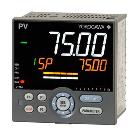
Chapter 3 Part Names 3.1 Names and Functions of Display Parts See the next page. IM 05P01B41-01EN... - Page 41 3.1 Names and Functions of Display Parts (9) Deviation indicator (1) PV display (2) Group display (4) Data display (3) Symbol display (10) Status indicator (5) Bar-graph display (11) Security indicator (6) Event indicator (7) Key navigation indicator (12) Ladder operation indicator (13) Loop 2 indicator (8) Parameter display level indicator (2) + (3) + (4) : Setpoint display...
- Page 42 3.1 Names and Functions of Display Parts No. in figure Name Description Displays PV. Displays an error code if an error occurs. PV display Displays the scrolling guide in the Menu Display and (white or red) Parameter Setting Display when the guide display ON/ OFF is set to ON. Displays a group number (1 to 16, or R) and terminal area (E1 to E4).
-
Page 43: Names And Functions Of Keys
3.2 Names and Functions of Keys (1) DISPLAY key (4) Light-loader interface (5) A/M key (2) PARAMETER key (6) User function keys (3) SET/ENTER key Up/Down/Left/Right arrow keys IM 05P01B41-01EN... - Page 44 The setting is switched between AUTO and MAN each A/M key time the key is pressed. The user can assign a function key. The UT75A has F1, F2, and Fn keys. User function keys The user can assign a function to the key. The function is set by the parameter.
- Page 45 3.2 Names and Functions of Keys Maintenance Port (Power supply is not required for the UT75A). The maintenance port is used to connect with the dedicated cable when using LL50A Parameter Setting Software (sold separately). The parameters can be set without supplying power to the UT75A. Maintenance port Upper surface UT75A CAUTION When using the maintenance port, do not supply power to the controller. Otherwise, the controller does not work normally.
-
Page 46: List Of Display Symbols
3.3 List of Display Symbols The following shows the parameter symbols, menu symbols, alphanumeric of guide, and symbols which are displayed on the UT75A. Figure (common to all display area) PV display (14 segments): Alphabet Symbol display and Data display (11 segments): Alphabet (lower-case) IM 05P01B41-01EN... - Page 47 3.3 List of Display Symbols Group display (7 segments): Alphabet None PV display (14 segments): Symbol Space ‘ IM 05P01B41-01EN...
-
Page 48: Brief Description Of Setting Details (Parameters)
Brief Description of Setting Details (Parameters) This manual describes the Setting Details as follows in addition to the functional Description. Setting Details (Display Example) Parameter Display Name Setting range Menu symbol symbol level Set a display value of setpoint of PV alarm, SP alarm, deviation alarm, output alarm, or velocity Alarm-1 to -8 alarm. - Page 49 Blank Page...
-
Page 50: Chapter 4 Basic Operation
Chapter 4 Basic Operation Overview of Display Switch and Operation Keys The following shows the transition of Operation Display, Operation Parameter Setting Display, and Setup Parameter Setting Display. The “Operation Parameter Setting Display” has the parameters for setting the functions necessary for the operation. The “Setup Parameter Setting Display” has the parameters for setting the basic functions of the controller. - Page 51 4.1 Overview of Display Switch and Operation Keys The display pattern of the UT75A is as follows; the Menu Display and Parameter Setting Display. For the Operation Display, see Chapter 6, “Monitoring and Control of Regular Operations.” Display Description The Menu Display is segmented by the function and optional terminal position.
- Page 52 4.1 Overview of Display Switch and Operation Keys Display Shown at the End (the Lowest Level) of the Parameter Setting Display As shown in the figure below, the END Display is shown to indicate the end of the Menu Display and Parameter Setting Display. There are no setting items. The scrolling guide of END is displayed. END is displayed. Basic Key Operation Sequence ● To move to the Setup Parameter Setting Display Hold down the PARAMETER key and the Left arrow key simultaneously for 3 seconds.
-
Page 53: How To Set Parameters
4.2 How to Set Parameters The following operating procedure describes an example of setting alarm setpoint (A1). Operation Hold down the PARAMETER key for 3 seconds in the Operation Display to call up the [MODE] Menu Display. Press the Right arrow key to display the [SP] Menu Display. Press the SET/ENTER key to display the [SP.J] Parameter Setting Display. - Page 54 4.2 How to Set Parameters Press the Down arrow key to display the [A1] Parameter Setting Display. Press the SET/ENTER key to blink the setpoint. Press the Up or Down arrow key to change the setpoint. (Change the setpoint using the Up/Down arrow keys to increase and decrease the value and the Left/Right arrow keys to move between digits.) Press the SET/ENTER key to register the setpoint (the setpoint stops blinking).
- Page 55 4.2 How to Set Parameters How to Set Parameter Setpoint Numeric Value Setting Display the Parameter Setting Display. Press the SET/ENTER key to move to the setting mode (the setpoint blinks). Press the Left arrow key to move one digit to the left. (Press the Right arrow key to move one digit to the right.) Press the Up or Down arrow key to change the setpoint.
- Page 56 4.2 How to Set Parameters Time (minute.second) Setting Example of 17 minutes 59 seconds Display the Parameter Setting Display. Press the SET/ENTER key to move to the setting mode (the setpoint blinks). Press the Left arrow key to move one digit to the left. (press the Right arrow key to move one digit to the right.) Press the Up or Down arrow key to change the setpoint.
- Page 57 Blank Page...
-
Page 58: Chapter 5 Quick Setting Function
Chapter 5 Quick Setting Function 5.1 Setting Using Quick Setting Function Description The Quick setting function is a function to easily set the basic function of the controller. The Quick setting function starts when the power is turned on after wiring. The Quick setting function can be used only when the control mode is Single-loop control. - Page 59 5.1 Setting Using Quick Setting Function Flowchart of Quick Setting Function Power ON Decide whether or not to use the Quick setting function. Press the UP arrow key to select YES. Press the SET/ENTER key to start the Quick setting function. Press the Down arrow key to select NO. Press the SET/ENTER key not to start the Quick setting function.
- Page 60 5.1 Setting Using Quick Setting Function Setting Example Set the following parameters to set to PID control, thermocouple Type K (range: 0.0 to 500.0ºC), and current control output. No need to change the parameters other than the following parameters. Set QSM = YES to enter the quick setting mode. (1) Set CNT = PID.
- Page 61 5.1 Setting Using Quick Setting Function Input Function Parameter Display Name Setting range Menu symbol symbol level OFF: Disable K1: -270.0 to 1370.0 ºC / -450.0 to 2500.0 ºF K2: -270.0 to 1000.0 ºC / -450.0 to 2300.0 ºF K3: -200.0 to 500.0 ºC / -200.0 to 1000.0 ºF J: -200.0 to 1200.0 ºC / -300.0 to 2300.0 ºF T1: -270.0 to 400.0 ºC / -450.0 to 750.0 ºF T2: 0.0 to 400.0 ºC / -200.0 to 750.0 ºF...
- Page 62 5.1 Setting Using Quick Setting Function Input Function (Continued) Parameter Display Name Setting range Menu symbol symbol level 0: No decimal place PV input scale 1: One decimal place decimal point EASY 2: Two decimal places position 3: Three decimal places 4: Four decimal places Maximum value of EASY PV input scale -19999 to 30000, (SL<SH),...
-
Page 63: Restarting Quick Setting Function
5.2 Restarting Quick Setting Function Once functions have been built using the Quick setting function, the Quick setting function does not start even when the power is turned on. The following methods can be used to restart the Quick setting function. ● Set the parameter QSM (Quick setting mode) to ON and turn on the power again. ● Set the parameter IN (PV input type) to OFF and turn on the power again. -
Page 64: Chapter 6 Monitoring And Control Of Regular Operations
Chapter 6 Monitoring and Control of Regular Operations 6.1 Monitoring and Control of Operation Displays 6.1.1 Operation Display Transitions in Single-loop Control, Cascade Primary- loop Control, Cascade Secondary-loop Control, Loop Control for Backup, and Loop Control with PV-hold Function. (The displays only for the Standard type are displayed in Cascade primary-loop control.) ► Display/Non-display of Operation Display: 13.3.5 Setting Display/Non-display of Operation Display ► Registration of SELECT Display: 13.1.3 Registering SELECT Display (Up to 5 displays) Standard Type SP Display (SP can be changed.) OUT Display (OUT can be changed in MAN mode.) -
Page 65: Position Proportional Type
6.1 Monitoring and Control of Operation Displays Position Proportional Type SP Display (SP can be changed.) Valve Position Display (display only) Position Proportional Computation Output Display (Factory default: non-display) PID Number Display (display only) (Factory default: non-display) Analog Input Displays (display only) (Factory default: non-display) PV: PV analog input, AIN2: AIN2 analog input (E2-terminal area), AIN4: AIN4 analog input (E4-terminal area) (Only for each aux. -
Page 66: Heating/Cooling Control
6.1 Monitoring and Control of Operation Displays Heating/cooling Control SP Display (SP can be changed.) Heating/cooling OUT Display (OUT can be changed in MAN mode.) C: cooling-side output, H: heating-side output PID Number Display (display only) (Factory default: non-display) Analog Input Displays (display only) (Factory default: non-display) PV: PV analog input, AIN2: AIN2 analog input (E2-terminal area), AIN4: AIN4 analog input (E4-terminal area) -
Page 67: Single-Loop Two-Position Two-Level Control
6.1 Monitoring and Control of Operation Displays Single-loop Two-position two-level control SP Display (SP can be changed.) OUT Display (Main setting-side OUT can be changed in MAN mode.) OUT Display (Sub-setting-side OUT can be changed in MAN mode.) PID Number Display (display only) (Factory default: non-display) Analog Input Displays (display only) (Factory default: non-display) PV: PV analog input, AIN2: AIN2 analog input (E2-terminal area),... -
Page 68: Operation Display Transitions In Loop Control With Pv Switching And Loop Control With Pv Auto-Selector
6.1 Monitoring and Control of Operation Displays 6.1.2 Operation Display Transitions in Loop Control with PV Switching and Loop Control with PV Auto-selector ► Display/non-display of Operation Display: 13.3.5 Setting Display/Non-display of Operation Display ► Registration of SELECT Display: 13.1.3 Registering SELECT Display (Up to 5 Displays) Standard Type SP Display (SP can be changed.) OUT Display (OUT can be changed in MAN mode.) PID Number Display (display only) (Factory default: non-display) Analog Input Displays (display only) -
Page 69: Position Proportional Type
6.1 Monitoring and Control of Operation Displays Position Proportional Type SP Display (SP can be changed.) Valve Position Display (display only) Position Proportional Computation Output Display (Factory default: non-display) PID Number Display (display only) (Factory default: non-display) Analog Input Displays (display only) PV: PV analog input, AIN2: AIN2 analog input (E2-terminal area), AIN4: AIN4 analog input (E4-terminal area) (Depends on the aux. -
Page 70: Heating/Cooling Control
6.1 Monitoring and Control of Operation Displays Heating/cooling Control SP Display (SP can be changed.) Heating/cooling OUT Display (OUT can be changed in MAN mode.) C: cooling-side output, H: heating-side output PID Number Display (display only) (Factory default: non-display) Analog Input Displays (display only) PV: PV analog input, AIN2: AIN2 analog input (E2-terminal area), AIN4: AIN4 analog input (E4-terminal area) (Depends on the aux. -
Page 71: Operation Display Transitions In Cascade Control
6.1 Monitoring and Control of Operation Displays 6.1.3 Operation Display Transitions in Cascade Control ► Display/non-display of Operation Display: 13.3.5 Setting Display/Non-Display of Operation Display ► Registration of SELECT Display: 13.1.3 Registering SELECT Display (Up to 5 Displays) Standard Type When the operation mode is Cascade: Loop-1 SP Display (SP can be changed.) PV display: Loop-1 PV Loop-2 OUT Display (display only) PV display: Loop-1 PV... - Page 72 6.1 Monitoring and Control of Operation Displays When the operation mode is AUTO or MAN: Loop-2 SP Display (SP can be changed.) PV display: Loop-2 PV LP2 lamp is lit. Loop-2 OUT Display (OUT can be changed in MAN mode.) PV display: Loop-2 PV LP2 lamp is lit. Loop-1 PID Number Display (display only) (Factory default: non-display) PV display: Loop-2 PV...
-
Page 73: Position Proportional Type
6.1 Monitoring and Control of Operation Displays Position Proportional Type When the operation mode is Cascade: Loop-1 SP Display (SP can be changed.) PV display: Loop-1 PV Valve Position Display (display only) PV display: Loop-1 PV LP2 lamp is lit. Position Proportional Computation Output Display (Factory default: non-display) PV display: Loop-1 PV LP2 lamp is lit. - Page 74 6.1 Monitoring and Control of Operation Displays When the operation mode is AUTO or MAN: Loop-2 SP Display (SP can be changed.) PV display: Loop-2 PV LP2 lamp is lit. Valve Position Display (display only) PV display: Loop-2 PV LP2 lamp is lit. Position Proportional Computation Output Display (Factory default: non-display) PV display: Loop-2 PV LP2 lamp is lit.
-
Page 75: Heating/Cooling Control
6.1 Monitoring and Control of Operation Displays Heating/cooling Control When the operation mode is Cascade: Loop-1 SP Display (SP can be changed.) PV display: Loop-1 PV Loop-2 Heating/cooling OUT Display (OUT can be changed in MAN mode.) PV display: Loop-1 PV C: cooling-side OUT, H: heating-side OUT LP2 lamp is lit. - Page 76 6.1 Monitoring and Control of Operation Displays When the operation mode is AUTO or MAN: Loop-2 SP Display (SP can be changed.) PV display: Loop-2 PV LP2 lamp is lit. Loop-2 Heating/cooling OUT Display (OUT can be changed in MAN mode.) PV display: Loop-2 PV C: cooling-side OUT, H: heating-side OUT LP2 lamp is lit.
-
Page 77: Operation Display Transitions In Dual-Loop Control
6.1 Monitoring and Control of Operation Displays 6.1.4 Operation Display Transitions in Dual-loop Control ► Display/non-display of Operation Display: 13.3.5 Setting Display/Non-Display of Operation Display ► Registration of SELECT Display: 13.1.3 Registering SELECT Display (Up to 5 Displays) Dual-loop control (loop-1) SP Display (SP can be changed.) Press F2 to switch between Loop-1 and Loop-2. -
Page 78: Dual-Loop Control (Loop-2)
6.1 Monitoring and Control of Operation Displays Dual-loop control (loop-2) SP Display (SP can be changed.) Press F2 to switch between Loop-1 and Loop-2. OUT Display (OUT can be changed in MAN mode.) PID Number Display (display only) (Factory default: non-display) Loop-1/Loop-2 PV Display (display only) PV display: Loop-1 PV Setpoint display: Loop-2 PV Analog Input Displays (display only) -
Page 79: Heating/Cooling Control
6.1 Monitoring and Control of Operation Displays Heating/cooling control Press F2 to switch between Loop-1 and Loop-2. Loop-1 SP Display (SP can be changed.) PV display: Loop-1 PV Loop-1 Heating/cooling OUT Display (OUT can be changed in MAN mode.) PV display: Loop-1 PV C: cooling-side OUT, H: heating-side OUT PID Number Display (display only) (Factory default: non-display) Loop-1/Loop-2 PV Display (display only) - Page 80 6.1 Monitoring and Control of Operation Displays Details of the Operation Display The following is the Operation Display types and each display and operation description. PV display Setpoint display Operation Display Display and operation description PV display: Displays measured input value (PV). Setpoint display: Displays and changes target setpoint (SP). Symbol Target setpoint Target setpoint (SP) number The Display is switched to the SP Display if the operation mode is switched to AUTO, CAS, LCL, or REM when other Operation Display is shown.
- Page 81 6.1 Monitoring and Control of Operation Displays (Continued) Operation Display Display and operation description When the program pattern operation. Symbol Current target setpoint The segment number for which operation is in progress. During program pattern operation when the right arrow key is held down SP Display Number of Current target setpoint segments The segment number for which operation is in progress.
- Page 82 6.1 Monitoring and Control of Operation Displays (Continued) Operation Display Display and operation description PV display: Displays measured input value (PV). Setpoint display: Displays control output value and changes control output value in MAN mode. Control output Symbol Target setpoint (SP) number Displays the valve's feedback input value (at 0 to 100% valve opening) in Position proportional control.
- Page 83 6.1 Monitoring and Control of Operation Displays (Continued) Operation Display Display and operation description PV display: Displays measured input value (PV). Setpoint display: Displays heating-side and cooling-side control output value and changes control output value in MAN mode. Heating-side control output Symbol of heating side Cooling-side control output Symbol of cooling side Target setpoint (SP) number When the control output value is less than 100%, one digit is displayed to the right of the decimal point.
- Page 84 6.1 Monitoring and Control of Operation Displays (Continued) Operation Display Display and operation description PV display: Displays measured input value (PV). Setpoint display: Displays PID number currently being used. PID Number Symbol PID number Display Target setpoint (SP) number Loop-1 PID number is displayed when the control mode is Cascade control and the operation mode is cascade.
- Page 85 6.1 Monitoring and Control of Operation Displays (Continued) Operation Display Display and operation description PV display: Displays measured input value (PV). Setpoint display: Displays PV, PV2, AIN2, or AIN4 analog input value. AIN2 auxiliary analog input value Symbol AIN2 input Analog Input Target setpoint (SP) number Display AIN4 auxiliary analog input value Symbol AIN4 input Target setpoint (SP) number...
-
Page 86: Setting Target Setpoint
6.2 Setting Target Setpoint Operation in the Operation Display Operation Bring the SP Display into view. Press the SET/ENTER key to move to the setting mode (the setpoint blinks). Press the Left arrow key to move one digit to the left. (Press the Right arrow key to move one digit to the right.) Press the Up or Down arrow key to change a setpoint. -
Page 87: Operation In Parameter Setting Display
6.2 Setting Target Setpoint Operation in Parameter Setting Display Setting Display Operation Display > Hold down the PARAMETER key for 3 Parameter Setting Display seconds (to [MODE] Menu Display) > Right arrow key (to [SP] Menu Display ) > SET/ENTER key (The setting parameter is displayed.) Press the Right arrow key until the [SP] Menu Display appears. In the Setting Display for the target setpoint parameter, pressing the Left or Right arrow keys changes the group. -
Page 88: Performing And Canceling Auto-Tuning
6.3 Performing and Canceling Auto-tuning Setting Display Operation Display > Hold down the PARAMETER key for Operation Mode Setting Display 3 seconds (to [MODE] Menu Display) > SET/ENTER key (The operation mode is displayed.) > Down arrow key (The operation mode is displayed.) The parameter AT is displayed when the operation mode is AUTO. - Page 89 6.3 Performing and Canceling Auto-tuning CAUTION Set the operation mode to AUTO and RUN to perform auto-tuning. Lamp Status Status STOP lamp CAS lamp MAN lamp During auto-tuning Unlit Unlit Blinking In Cascade control, perform Loop-2 auto-tuning in AUTO and RUN modes, then Loop-1 auto-tuning in Cascade and RUN modes. Lamp Status Status STOP lamp...
- Page 90 6.3 Performing and Canceling Auto-tuning When SP bias in auto-tuning is set Auto-tuning in progress MAN lamp blinking SP bias in auto-tuning SP+AT.BS (negative setpoint) Temperature Control output Time PID control using PID ON/OFF control constants calculated from the AT results AT = Started There is a hysteresis of 0.25% of the input range above and below SP. Tuning Point and Storage Location of Tuning Results The tuning point when performing auto-tuning is the target setpoint that is currently used for control computation.
-
Page 91: Adjusting Pid Manually
6.4 Adjusting PID Manually Setting Display Operation Display > Hold down the PARAMETER key for 3 Parameter Setting Display seconds (to [MODE] Menu Display) > Right arrow key (to [PID] Menu Display ) > SET/ENTER key (The setting parameter is displayed.) > Down arrow key (The setting parameter is displayed.) In the Setting Display for the PID parameters, Displays can be arbitrarily switched using the Up, Down, Left or Right arrow... - Page 92 6.4 Adjusting PID Manually There are 16 groups of PID parameters. In Cascade control, both Loop-1 and Loop-2 have 16 groups. The PID parameters can be selected by using the following two methods: (1) SP group number selection The PID group which is set in the PID number selection (PIDN) of each SP group is used.
- Page 93 6.4 Adjusting PID Manually Description Description and Tuning of Proportional Band The proportional band is defined as the amount of change in input (or deviation), as a percent of span, required to cause the control output to change from 0% to 100%. Because a narrower proportional band gives greater output change for any given deviation, it therefore also makes the control performance more susceptible to oscillation.
- Page 94 6.4 Adjusting PID Manually Description and Tuning of Integral Time The integral action (I action) is a function that will automatically diminish the offset (steady-state deviation) that is inherently unavoidable with proportional action alone. The integral action continuously increases or decreases the output in proportion to the time integral of the deviation (the product of the deviation and the time that the deviation continues.) The integral action is normally used together with proportional action as proportional- plus-integral action (PI action).
- Page 95 6.4 Adjusting PID Manually Description and Tuning of Derivative Time If the control object has a large time constant or dead time, the corrective action will be too slow with proportional action or proportional-plus-integral action alone, causing overshoot. However, even just sensing whether the deviation is on an increasing or a decreasing trend and adding some early corrective action can improve the controllability. Thus the derivative action (D action) is action that changes the output in proportion to the deviation derivative value (rate-of-change).
- Page 96 6.4 Adjusting PID Manually Manual PID Tuning Procedure (1) In principle, auto-tuning must be used. (2) Tune PID parameters in the order of P, I, and D. Adjust a numeric slowly by observing the result, and keep notes of what the progress is. (3) Gradually reduce P from a larger value. When the PV value begins to oscillate, stop tuning and increase the value somewhat.
-
Page 97: Setting Alarm Setpoint
6.5 Setting Alarm Setpoint Setting Display Operation Display > Hold down the PARAMETER key for 3 Parameter Setting Display seconds (to [MODE] Menu Display) > Right arrow key (to [SP] Menu Display) > SET/ENTER key (The setting parameter is displayed.) > Down arrow key (The setting parameter is displayed.) In the setting Display for the alarm parameters, Displays can be arbitrarily switched using the Up, Down, Left or Right arrow... -
Page 98: Selecting Target Setpoint Number (Spno)
6.6 Selecting Target Setpoint Number (SPNO) Setting Display Operation Display > Hold down the PARAMETER key for 3 Parameter Setting Display seconds (to [MODE] Menu Display) > SET/ENTER key (The setting parameter is displayed.) > Down arrow key (The setting parameter is displayed.) Setting Details Parameter Display Name Setting range Menu symbol... -
Page 99: Switching Operation Modes
6.7 Switching Operation Modes 6.7.1 Switching between AUTO and MAN Direct Operation by A/M Key Operation MAN lamp is lit in MAN mode. Each time you press the key, AUTO and MAN is switched alternately. Description AUTO/MAN switching can be performed by any of the following: (1) A/M key (2) Contact input (status or edge) (3) Communication (4) User function key AUTO... - Page 100 6.7 Switching Operation Modes Operation Display in AUTO and MAN Modes “OUT” is displayed on Symbol display and “Output value” is displayed on Data display in MAN mode. (The OUT Display is shown.) Sub-setting-side OUT Display is shown in Two-position two-level control. SP Display is shown in AUTO mode. Operation Display in AUTO and MAN Modes in Heating/cooling Control In MAN mode, the Display is as follows.
-
Page 101: Switching Between Cas (Cascade), Auto, And Man
6.7 Switching Operation Modes 6.7.2 Switching between CAS (Cascade), AUTO, and MAN Setting Display Operation Mode Setting Display Operation Display > Hold down the PARAMETER key for 3 seconds (to [MODE] Menu Display) > SET/ENTER key (The operation mode is displayed.) > Down arrow key (The operation mode is displayed.) Setting Details Parameter Display Name... - Page 102 6.7 Switching Operation Modes Output Action in CAS/AUTO/MAN Switch Switch Output action CAS→AUTO The control output value does not bump (bumpless). The control output value bumps to the manual preset output value. CAS→MAN Or holds the control output value from CAS mode. AUTO→CAS The control output value does not bump (bumpless). The control output value bumps to the manual preset output value.
-
Page 103: Switching Between Stop And Run
6.7 Switching Operation Modes 6.7.3 Switching between STOP and RUN Setting Display Operation Mode Setting Display Operation Display > Hold down the PARAMETER key for 3 seconds (to [MODE] Menu Display) > SET/ENTER key (The operation mode is displayed.) > Down arrow key (The operation mode is displayed.) Factory default: The parameter S.R is not displayed because STOP/RUN switch is assigned to the contact input. - Page 104 6.7 Switching Operation Modes Output Control output Preset output RUN → STOP STOP → RUN ► Preset output value: 10.12.1 Setting Output Value in STOP Mode (Preset Output) Operation Display in STOP and RUN Modes “STOP” is displayed on Symbol display and “Output value” is displayed on Data display in STOP mode.
- Page 105 6.7 Switching Operation Modes Operation Display in STOP and RUN Modes in Heating/cooling Control In STOP mode in Heating/cooling control, the display is as follows. The cooling-side preset output is displayed on the left of the symbol “ST” and heating-side preset output is displayed on the right. The display at operation start differs depending on AUTO or MAN mode. SP Display is shown in AUTO mode and Heat/cool OUT Display is shown in MAN mode.
-
Page 106: Switching Between Rem (Remote) And Lcl (Local)
6.7 Switching Operation Modes 6.7.4 Switching between REM (Remote) and LCL (Local) Setting Display Operation Mode Setting Display Operation Display > Hold down the PARAMETER key for 3 seconds (to [MODE] Menu Display) > SET/ENTER key (The operation mode is displayed.) > Down arrow key (The operation mode is displayed.) Setting Details Parameter Display Name... -
Page 107: Switching Between P.run (Start Of Program Pattern Operation) And P.stop (Stop Of Program Pattern Operation)
6.7 Switching Operation Modes SP Action in REM/LCL Switch Switch SP action LCL→REM The local target setpoint bumps to the remote target setpoint. The remote target setpoint bumps to the local target setpoint. Or forces the local REM→LCL target setpoint to track the remote target setpoint. ► Tracking: 9.4 Forcing SP to Track Remote Input (SP Tracking) Lamp Status Status REM lamp... - Page 108 6.7 Switching Operation Modes Description P.RUN/P.STOP (Start/stop of program pattern operation) switching can be performed by any of the following: (1) Parameter (2) Contact input (3) Communication (4) User function key ► Switch by contact input: 12.1 Setting Contact Input Function • If parameter PGTY = 0 and the segment time of segment 1 is not set, the operation mode cannot be switched to P.RUN (start of program operation).
-
Page 109: Enabling/Disabling Hold-Mode (Hold) Of Program Operation
6.7 Switching Operation Modes 6.7.6 Enabling/Disabling Hold-mode (HOLD) of Program Operation Setting Display Parameter Setting Display Operation Display > Hold down the PARAMETER key for 3 seconds (to [MODE] Menu Display) > SET/ENTER key (The operation mode is displayed.) > Down arrow key (The Setup Parameter is displayed.) Setting Details Parameter Display Name Setting range... -
Page 110: Executing Advance (Adv) Function
6.7 Switching Operation Modes 6.7.7 Executing Advance (ADV) Function Setting Display Parameter Setting Display Operation Display > Hold down the PARAMETER key for 3 seconds (to [MODE] Menu Display) > SET/ENTER key (The operation mode is displayed.) > Down arrow key (The Setup Parameter is displayed.) Setting Details Parameter Display Name Setting range... -
Page 111: Manipulating Control Output During Manual Operation
Manipulating Control Output during Manual Operation Operation Direct key method The value specified by the Up and Down arrow keys is output as is. Press the Up arrow key to increase the control output. Press the Down arrow key to decrease the control output. - Page 112 6.8 Manipulating Control Output during Manual Operation Setting Details Parameter Display Name Setting range Menu symbol symbol level In manual operation mode, you can use the direct key method or the SET/ENT key method to control the output value. (Note) Direct key method Manual output The value specified by the MAN.T...
-
Page 113: Releasing On-State (Latch) Of Alarm Output
6.9 Releasing On-State (Latch) of Alarm Output Description Alarm latch can be released by any of the following. (1) User function key (2) Communication (3) Contact input For the switching operation by using the above, the last switching operation is performed. Releasing the alarm latch function releases all of the latched alarm outputs. By factory default, the function is not assigned to the user function key and contact input. -
Page 114: Chapter 7 Input (Pv, Remote, And Auxiliary Analog) Functions
Chapter 7 Input (PV, Remote, and Auxiliary Analog) Functions 7.1 Setting Functions of PV Input, Remote Input, and Auxiliary Analog Input 7.1.1 Setting Input Type, Unit, Range, Scale, and Decimal Point Position Description The figure below describes the case of PV input. The remote input and auxiliary analog input can be set in the same way. Example of Temperature Input The figure below is an example of setting Type K thermocouple and a measurement range of 0.0 to 800.0 ºC. - Page 115 7.1 Setting Functions of PV Input, Remote Input, and Auxiliary Analog Input Setting Details Parameter Display Name Setting range Menu symbol symbol level OFF: Disable K1: -270.0 to 1370.0 ºC / -450.0 to 2500.0 ºF K2: -270.0 to 1000.0 ºC / -450.0 to 2300.0 ºF K3: -200.0 to 500.0 ºC / -200.0 to 1000.0 ºF J: -200.0 to 1200.0 ºC / -300.0 to 2300.0 ºF T1: -270.0 to 400.0 ºC / -450.0 to 750.0 ºF T2: 0.0 to 400.0 ºC / -200.0 to 750.0 ºF...
- Page 116 7.1 Setting Functions of PV Input, Remote Input, and Auxiliary Analog Input (Continued) Parameter Display Name Setting range Menu symbol symbol level Depends on the input type. - For temperature input - Set the temperature range Maximum value of PV EASY that is actually controlled. input range (RL<RH) - For voltage / current input - Set the range of a voltage / current signal that is applied.
- Page 117 7.1 Setting Functions of PV Input, Remote Input, and Auxiliary Analog Input Parameter Display Name Setting range Menu symbol symbol level Minimum value of PV EASY input scale Minimum value of PV2 EASY input scale -19999 to 30000, (SL<SH), (Scaling) | SH - SL | ≤ 30000 Minimum value of AIN2 EASY AIN2 aux. analog input scale Minimum value of AIN4 EASY AIN4 remote input scale...
-
Page 118: Setting Burnout Detection For Input
7.1 Setting Functions of PV Input, Remote Input, and Auxiliary Analog Input 7.1.2 Setting Burnout Detection for Input Description The input value when input burnout occurs can be determined. The input value is 105.0% of the input range when the upscale is set, and -5.0% of the input range when the downscale is set. Burnout detection is activated for TC, RTD, and standard signal (0.4–2 V or 1–5 V). For standard signal, burnout is determined to have occurred if it is 0.1 V or less for the range of 0.4–2 V and 1–5V, or if it is 0.4 mA or less for the range of 4–20 mA. -
Page 119: Setting Reference Junction Compensation (Rjc) Or External Reference
External Reference Junction Compensation (ERJC) For TC input, a temperature compensation value for external device can be set. The external RJC can be used only when RJC = OFF. UT75A Terminal block Compensating lead wire Furnace UT75A... -
Page 120: Correcting Input Value
7.1 Setting Functions of PV Input, Remote Input, and Auxiliary Analog Input 7.1.4 Correcting Input Value (1) Setting Bias and Filter Description PV Input Bias The PV input bias allows bias to be summed with input to develop a measured value for display and control use inside the controller. This function can also be used for fine adjustment to compensate for small inter- instrument differences in measurement reading that can occur even if all are within the specified instrument accuracies. - Page 121 7.1 Setting Functions of PV Input, Remote Input, and Auxiliary Analog Input Setting Details Parameter Display Name Setting range Menu symbol symbol level -100.0 to 100.0% of PV PV input bias EASY input range span (EUS) PV input filter EASY OFF, 1 to 120 s Parameter Display Name Setting range Menu symbol symbol level PV analog input bias PV2 analog input bias -100.0 to 100.0% of each A.BS...
-
Page 122: Setting Square Root Extraction And Low Signal Cutoff Point
7.1 Setting Functions of PV Input, Remote Input, and Auxiliary Analog Input (2) Setting Square Root Extraction and Low Signal Cutoff Point Description This calculation is used to convert, for example, a differential pressure signal from a throttling flow meter such as an orifice and nozzle into a flow-rate signal. There is no hysteresis for low signal cutoff point. Output Output Low signal cutoff Low signal cutoff point is variable. point is variable. Input Input Output = Input Output = Input The slope equals “1”... -
Page 123: Setting 10-Segment/20-Segment Linearizer
7.1 Setting Functions of PV Input, Remote Input, and Auxiliary Analog Input (3) Setting 10-segment/20-segment Linearizer Description A total of up to four 10-segment linearizers or a total of up to two 20-segment linearizers can be used for the input unit and output unit. For the position used by the segment linearizer, see the function block diagram. ► Function block diagram: 8.1 Setting Control Mode (CTLM) ► Output Linearizer: 10.13 Setting 10-segment Linearizer for Output 10-Segment Linearizer Bias (10-segment linearizer only) This function is used to correct an input signal affected by sensor deterioration. The corrected values are obtained by adding the corresponding bias values to each of the 11 points of optionally set input values. - Page 124 7.1 Setting Functions of PV Input, Remote Input, and Auxiliary Analog Input In 20-segment linearizer approximation, output values for 21 input values can be assigned. 20-segment linearizer output B11(2) B2(2) B11(1) B10(1) B9(1) B8(1) B7(1) B6(1) B5(1) B4(1) B3(1) 20-segment B2(1) linearizer B1(1) input A1(1) A3(1) A5(1) A7(1) A9(1) A11(1) A3(2) A5(2) A7(2) A9(2) A11(2) -0.5% A10(1) A2(2) A4(2) A6(2) A8(2) A10(2) 105.0% A2(1) A4(1)
- Page 125 7.1 Setting Functions of PV Input, Remote Input, and Auxiliary Analog Input Parameters are set in the following order. (1) PYS: Specifies where the 10-segment linearizer function is used. Setpoints PV, PV2, AIN2, and AIN4 function before the input ladder calculation section. Setpoint PVIN functions after the input ladder calculation section. ► Where the 10-segment linearizer function is used; Function block diagrams in 8.1 Setting Control Mode (CTLM) (2) PMD: Specifies whether to use it as a 10-segment linearizer bias or a 10-segment linearizer approximation. (3) A1 to A11, B1 to B11: Sets the segment linearizer input and segment linearizer output.
-
Page 126: Setting Ratio Bias/Filter
7.1 Setting Functions of PV Input, Remote Input, and Auxiliary Analog Input 7.1.5 Setting Ratio bias/filter Description Ratio bias computing performs ratio computation and bias addition for remote setpoints. SP = Remote input x Remote input ratio (RT) + Remote input bias (RBS) Setting Details Parameter Display Name Setting range Menu symbol symbol level Remote input ratio 0.001 to 9.999 100.0 to 100.0% of PV Remote input bias input range span (EUS) Remote input filter OFF, 1 to 120 s Note 1: In Cascade control, PV input terminal is for Loop-1 and PV2 input terminal is for Loop-2. -
Page 127: Setting Input Sampling Period (Control Period)
7.2 Setting Input Sampling Period (Control Period) Setting Details Parameter Display Name Setting range Menu symbol symbol level 50: 50 ms Input sampling period 100: 100 ms (control period) 200: 200 ms Note: 50 ms; Available when the control mode is not Cascade control (CTLM≠CAS) and the following functions are not used: "SUPER" function, "SUPER 2" function. 7-14 IM 05P01B41-01EN... -
Page 128: Using 4-Wire Rtd As Pv Input
7.3 Using 4-wire RTD as PV Input Description If suffix code type 1 is 5 (dual-loop type), a 4-wire RTD can be used as the PV of the secondary loop. ► LL50A Parameter Setting Software: LL50A Parameter Setting Software User’s Manual Setting Details Parameter Display Name Setting range Menu symbol symbol level 3-W: 3-wire system RTD.S RTD wiring system 4-W: 4-wire system 7-15 IM 05P01B41-01EN... -
Page 129: Using Larger, Smaller, Average, Or Difference Of Two To Four Inputs As Pv
7.4 Using Larger, Smaller, Average, or Difference of Two to Four Inputs as PV Description Loop control with PV auto-selector function automatically selects or calculates the larger, smaller, average, or difference of multiple (two to four) inputs and uses the result as PV. The larger, smaller, and average are automatically computed based on the specified number of inputs. -
Page 130: Setting Remote Input Method
7.5 Setting Remote Input Method Description There are two methods for remote input: analog input and communication. Decide which to use among two methods in advance. Program pattern operation Analog input: Remote setting using external analog signal (AIN4 terminal) Communication: Remote setting via external communication. Analog input Target setpoints 1 to 20 REMOTE... -
Page 131: Adjusting Pv Range For Loop Control With Pv Switching Or Loop Control With Pv Auto-Selector
Adjusting PV Range for Loop Control with PV Switching or Loop Control with PV Auto-selector Description Loop control with PV switching and Loop control with PV auto-selector need to determine the PV range for control if the measurement ranges of two input signals are different. The figure below is an example of setting PV input range of 0 to 200ºC, PV2 terminal input of 100 to 800ºC, and control PV range of 0 to 800ºC. -
Page 132: Setting Pv Switching Methods Of Loop Control With Pv Switching
7.7 Setting PV Switching Methods of Loop Control with PV Switching Description PV switching method of Loop control with PV switching can be set when the control mode is Loop control with PV switching. ► Block diagram of Loop control with PV switching: 8.1.6 Loop Control with PV Switching, Heating/cooling Loop Control with PV Switching, and Position Proportional Loop Control with PV Switching Input 1: PV terminal input Input 2: AIN4 terminal input... - Page 133 7.7 Setting PV Switching Methods of Loop Control with PV Switching Switching within the Temperature Range (High-temperature side) (Parameter PV.2C=3) This method automatically switches PV within the range of input switching PV high limit and low limit. It should be selected in case where a sudden change in PV must be avoided. PV rising process Input 2 (High-temperature side) PV.HL PV.LL Input 1...
- Page 134 7.7 Setting PV Switching Methods of Loop Control with PV Switching Switching at the Input Switching PV High Limit (Parameter PV.2C=1) This method automatically switches two inputs at switching point (input switching PV high limit) It should be selected in case where a sudden change in PV is allowed. Control output will change smoothly (i.e., without any bumps) when PV switches. Hysteresis (0.5% of PV range span) is provided around the switching point.
- Page 135 7.7 Setting PV Switching Methods of Loop Control with PV Switching Switching by Contact Input (Parameter PV.2C=2) This method switches two inputs by contact input ON/OFF. When the contact input is OFF, PV = Input 1 (low-temperature side). When the contact input is ON, PV = Input 2 (high-temperature side). Input 2 (High-temperature side) Input 1 (Low-temperature side) Time Input 1 Input 2...
-
Page 136: Chapter 8 Control Functions
Chapter 8 Control Functions 8.1 Setting Control Mode (CTLM) 8.1.1 Single-loop Control, Single-loop Heating/cooling Control, Single-loop Position Proportional Control, and Single-loop Two-position Two-level Control Setting Details Parameter Name Display level Setting range Menu symbol symbol SGL: Single-loop control CAS1: Cascade primary-loop control CAS2: Cascade secondary-loop control CAS: Cascade control BUM: Loop control for backup CTLM Control mode PVSW: Loop control with PV switching PVSEL: Loop control with PV auto- selector... -
Page 137: Single-Loop Control Function Block Diagram
n Single-loop Control Function Block Diagram Remote input can be used when the Feedforward input can be used when DI46 is equipped when the suffix code: Communication Equipped as standard Type 2 = 1, 2 or 3. suffix code: Type 2 = 1, 2 or 3. the suffix code: Type 2 = 2. - Page 138 Output limiter OH, OL Input error preset output Normal When sensor burnout occurs Manual preset output MPON Manual operation Output limiter OH, OL OLMT AUTO AUTO (ON)/MAN (OFF) switch Preset output STOP STOP (ON)/RUN (OFF) switch * After the control output terminal is specified by the parameter OT, Output terminal assignment other current output terminals can be used as retransmission output.
-
Page 139: Single-Loop Heating/Cooling Control Function Block Diagram
n Single-loop Heating/cooling Control Function Block Diagram DI46 is equipped when the suffix code: Remote input can be used when the Communication Equipped as standard Type 2 = 1, 2 or 3. suffix code: Type 2 = 1, 2 or 3. *1: RS-485, Ethernet, PROFIBUS-DP, PV input Remote input Contact inputs DeviceNet, CC-Link... - Page 140 Manual preset output MPON Manual operation AUTO AUTO (ON)/MAN (OFF) switch Heating/cooling computation Manual output is prioritized even if sensor burnout occurs in MAN. Heating-side output limiter Cooling-side output limiter Input error preset output Input error preset output OH, OL OHc, OLc Normal Normal...
-
Page 141: Single-Loop Position Proportional Control Function Block Diagram
n Single-loop Position Proportional Control Function Block Diagram DI46 is equipped when the suffix code: Remote input can be used when the Feedforward input can be used when Equipped as standard Communication Type 2 = 1, 2 or 3. suffix code: Type 2 = 1, 2 or 3. the suffix code: Type 2 = 2. - Page 142 Output limiter OH, OL In Estimating-type position proportional control, the limiter function does not work on output operation. Input error preset output The reverse-signal relay turns on when being limited by low limit. Normal The direct-signal relay turns on when being limited by high limit. When sensor burnout occurs In Manual operation, the relay turns on while the key is pressed.
-
Page 143: Single-Loop Two-Position Two-Level Control Function Block Diagram
n Single-loop Two-position Two-level Control Function Block Diagram DI46 is equipped when the suffix code: Remote input can be used when the Equipped as standard Communication Type 2 = 1, 2 or 3. suffix code: Type 2 = 1, 2 or 3. *1: RS-485, Ethernet, PROFIBUS-DP, PV input Remote input Contact inputs DeviceNet, CC-Link... - Page 144 Manual output is prioritized even if sensor burnout occurs in MAN. Input error preset output Input error preset output Normal Normal When sensor burnout occurs When sensor burnout occurs Manual operation Manual operation AUTO AUTO AUTO (ON)/MAN (OFF) switch Preset output Sub-preset output SU.PO STOP...
- Page 145 8.1 Setting Control Mode (CTLM) Intentionally blank 8-10 IM 05P01B41-01EN...
-
Page 146: Cascade Primary-Loop Control
8.1 Setting Control Mode (CTLM) 8.1.2 Cascade Primary-loop Control Setting Details Parameter Display Name Setting range Menu symbol symbol level SGL: Single-loop control CAS1: Cascade primary-loop control CAS2: Cascade secondary-loop control CAS: Cascade control BUM: Loop control for backup CTLM Control mode PVSW: Loop control with PV switching PVSEL: Loop control with PV auto-selector PVHD: Loop control with PV-hold function... -
Page 147: Cascade Primary-Loop Control Function Block Diagram
n Cascade Primary-loop Control Function Block Diagram Output tracking input can be used when DI46 is equipped when the suffix code: Remote input can be used when the the suffix code: Type 2 = 1, 2 or 3. Type 2 = 1, 2 or 3. Equipped as standard suffix code: Type 2 = 2. - Page 148 Output limiter OH, OL Input error preset output Normal AUTO (ON)/MAN (OFF) switch When sensor burnout occurs MPON Manual preset output Manual operation Output tracking input Output limiter OH, OL OLMT AUTO Output limiter OH, OL Preset output Output tracking switch (Tracking at ON) STOP STOP (ON)/RUN (OFF) switch Equipped as standard...
- Page 149 8.1 Setting Control Mode (CTLM) Intentionally blank 8-14 IM 05P01B41-01EN...
-
Page 150: Cascade Secondary-Loop Control, Cascade Secondary-Loop Heating/Cooling Control, And Cascade Secondary-Loop Position Proportional Control
8.1 Setting Control Mode (CTLM) 8.1.3 Cascade Secondary-loop Control, Cascade Secondary-loop Heating/ cooling Control, and Cascade Secondary-loop Position Proportional Control Setting Details Parameter Display Name Setting range Menu symbol symbol level SGL: Single-loop control CAS1: Cascade primary-loop control CAS2: Cascade secondary-loop control CAS: Cascade control BUM: Loop control for backup CTLM Control mode PVSW: Loop control with PV switching PVSEL: Loop control with PV auto-selector... -
Page 151: Cascade Secondary-Loop Control Function Block Diagram
n Cascade Secondary-loop Control Function Block Diagram DI46 is equipped when the suffix code: Cascade input can be used when the Equipped as standard Type 2 = 1, 2 or 3. suffix code: Type 2 = 1, 2 or 3. Cascade input PV input Contact inputs (from Loop-1 controller) AIN4 DI46... - Page 152 Output limiter OH, OL Input error preset output Normal When sensor burnout occurs Manual preset output MPON Manual operation Output limiter OH, OL OLMT AUTO Preset output STOP * After the control output terminal is specified by the parameter OT, other current output terminals can be used as retransmission output.
-
Page 153: Cascade Secondary-Loop Heating/Cooling Control Function Block Diagram
n Cascade Secondary-loop Heating/cooling Control Function Block Diagram DI46 is equipped when the suffix code: Cascade input can be used when the Equipped as standard Type 2 = 1, 2 or 3. suffix code: Type 2 = 1, 2 or 3. Cascade input PV input Contact inputs (from Loop-1 controller) AIN4 DI46... - Page 154 MPON Manual preset output Manual operation AUTO Heating/cooling computation Manual output is prioritized even if sensor burnout occurs in MAN. Heating-side output limiter Cooling-side output limiter Input error preset output Input error preset output OH, OL OHc, OLc Normal Normal When sensor When sensor Heating-side preset output...
-
Page 155: Cascade Secondary-Loop Position Proportional Control Function Block Diagram
n Cascade Secondary-loop Position Proportional Control Function Block Diagram Cascade input can be used when the DI46 is equipped when the suffix code: Equipped as standard suffix code: Type 2 = 1, 2 or 3. Type 2 = 1, 2 or 3. Cascade input PV input (from Loop-1 controller) Contact inputs AIN4 DI46... - Page 156 Output limiter OH, OL In Estimating-type position proportional control, the limiter function does not work on output operation. Input error preset output The reverse-signal relay turns on when being limited by low limit. The direct-signal relay turns on when being limited by high limit. Normal When sensor burnout occurs...
- Page 157 8.1 Setting Control Mode (CTLM) Intentionally blank 8-22 IM 05P01B41-01EN...
-
Page 158: Cascade Control, Cascade Heating/Cooling Control, And Cascade Position Proportional Control
8.1 Setting Control Mode (CTLM) 8.1.4 Cascade Control, Cascade Heating/cooling Control, and Cascade Position Proportional Control Setting Details Parameter Display Name Setting range Menu symbol symbol level SGL: Single-loop control CAS1: Cascade primary-loop control CAS2: Cascade secondary-loop control CAS: Cascade control CTLM Control mode BUM: Loop control for backup PVSW: Loop control with PV switching PVSEL: Loop control with PV auto- selector PVHD: Loop control with PV-hold... -
Page 159: Cascade Control Function Block Diagram
n Cascade Control Function Block Diagram DI46 is equipped when the suffix code: Remote input can be used when the Loop-2 input can be used when the Type 2 = 1, 2 or 3. suffix code: Type 2 = 2. suffix code: Type 2 = 1, 2 or 3. - Page 160 Output limiter OH, OL Input error preset output Normal When Loop-2 sensor burnout occurs Loop-2 parameters Manual preset output MPON Manual operation Output limiter OH, OL OLMT CAS, AUTO C/A/M Preset output STOP STOP (ON)/RUN (OFF) switch * After the control output terminal is specified by the parameter OT, Output terminal assignment other current output terminals can be used as retransmission output.
-
Page 161: Cascade Heating/Cooling Control Function Block Diagram
n Cascade Heating/cooling Control Function Block Diagram DI46 is equipped when the suffix code: Loop-2 input can be used when the Remote input can be used when the Equipped as standard Type 2 = 1, 2 or 3. suffix code: Type 2 = 2. suffix code: Type 2 = 1, 2 or 3. - Page 162 Manual preset output MPON Manual operation CAS, AUTO C/A/M Heating/cooling computation Manual output is prioritized even if Loop-2 parameters sensor burnout occurs in MAN. Heating-side output limiter Cooling-side output limiter Input error preset output Input error preset output OH, OL OHc, OLc Normal Normal...
-
Page 163: Cascade Position Proportional Control Function Block Diagram
n Cascade Position Proportional Control Function Block Diagram DI46 is equipped when the suffix code: Remote input can be used when the Loop-2 input can be used when the Equipped as standard Type 2 = 1, 2 or 3. suffix code: Type 2 = 2. suffix code: Type 2 = 1, 2 or 3. - Page 164 Output limiter In Estimating-type position proportional control, the limiter function OH, OL Input error preset output does not work on output operation. Normal The reverse-signal relay turns on when being limited by low limit. When Loop-2 sensor burnout occurs The direct-signal relay turns on when being limited by high limit. In Manual operation, the relay turns on while the key is pressed.
- Page 165 8.1 Setting Control Mode (CTLM) Intentionally blank 8-30 IM 05P01B41-01EN...
-
Page 166: Loop Control For Backup, Heating/Cooling Loop Control For Backup, And Position Proportional Loop Control For Backup
8.1 Setting Control Mode (CTLM) 8.1.5 Loop Control for Backup, Heating/cooling Loop Control for Backup, and Position Proportional Loop Control for Backup Setting Details Parameter Display Name Setting range Menu symbol symbol level SGL: Single-loop control CAS1: Cascade primary-loop control CAS2: Cascade secondary-loop control CAS: Cascade control CTLM Control mode BUM: Loop control for backup PVSW: Loop control with PV switching PVSEL: Loop control with PV auto- selector PVHD: Loop control with PV-hold... -
Page 167: Loop Control For Backup Function Block Diagram
n Loop Control for Backup Function Block Diagram Output tracking input can be used when DI46 is equipped when the suffix code: Remote input can be used when the Equipped as standard the suffix code: Type 2 = 1, 2 or 3. Type 2 = 1, 2 or 3. suffix code: Type 2 = 2. - Page 168 Output limiter Input error preset output OH, OL Normal AUTO (ON)/MAN (OFF) switch When sensor burnout occurs Manual preset output MPON Manual operation Output tracking input Output limiter OH, OL OLMT AUTO Output limiter OH, OL Preset output Output tracking switch (Tracking at ON) STOP STOP (ON)/RUN (OFF) switch * After the control output terminal is specified by the parameter OT,...
-
Page 169: Heating/Cooling Loop Control For Backup Function Block Diagram
n Heating/cooling Loop Control for Backup Function Block Diagram Output tracking input can be used when DI46 is equipped when the suffix code: Remote input can be used when the the suffix code: Type 2 = 1, 2 or 3. Type 2 = 1, 2 or 3. Equipped as standard suffix code: Type 2 = 2. - Page 170 AUTO (ON)/MAN (OFF) switch Manual preset output MPON AUTO Output tracking input Manual operation Output limiter OH, OL Output tracking is prioritized even if sensor burnout Output tracking switch (Tracking at ON) occurs in the output tracking operation. Manual output is prioritized even if Heating/cooling computation sensor burnout...
-
Page 171: Position Proportional Loop Control For Backup Function Block Diagram
n Position Proportional Loop Control for Backup Function Block Diagram Output tracking input can be used when DI46 is equipped when the suffix code: Remote input can be used when the Equipped as standard the suffix code: Type 2 = 1, 2 or 3. Type 2 = 1, 2 or 3. suffix code: Type 2 = 2. - Page 172 In Estimating-type position proportional control, the limiter function Output limiter OH, OL does not work on output operation. Input error preset output The reverse-signal relay turns on when being limited by low limit. Normal The direct-signal relay turns on when being limited by high limit. When sensor burnout occurs In Manual operation, the relay turns on while the...
- Page 173 8.1 Setting Control Mode (CTLM) Intentionally blank 8-38 IM 05P01B41-01EN...
-
Page 174: Loop Control With Pv Switching, Heating/Cooling Loop Control With Pv Switching, And Position Proportional Loop Control With Pv Switching
8.1 Setting Control Mode (CTLM) 8.1.6 Loop Control with PV Switching, Heating/cooling Loop Control with PV Switching, and Position Proportional Loop Control with PV Switching Setting Details Parameter Display Name Setting range Menu symbol symbol level SGL: Single-loop control CAS1: Cascade primary-loop control CAS2: Cascade secondary-loop control CAS: Cascade control BUM: Loop control for backup CTLM Control mode PVSW: Loop control with PV switching PVSEL: Loop control with PV auto-selector PVHD: Loop control with PV-hold... -
Page 175: Loop Control With Pv Switching Function Block Diagram
n Loop Control with PV Switching Function Block Diagram PV input 2 can be used when the suffix code: Type 2 = 1, 2 or 3. Remote input can be used when the DI46 is equipped when the suffix code: Equipped as standard Aux. analog (remote) input (E4-terminal area) suffix code: Type 2 = 2. - Page 176 Output limiter OH, OL Input error preset output Normal When sensor burnout occurs Sensor burnout occurs when PV or AIN4 input burnout occurs. However, burnout is not detected if input is not connected. Manual preset output MPON Manual operation Output limiter OH, OL OLMT AUTO...
-
Page 177: Heating/Cooling Loop Control With Pv Switching Function Block Diagram
n Heating/cooling Loop Control with PV Switching Function Block Diagram PV input 2 can be used when the suffix code: Type 2 = 1, 2 or 3. Remote input can be used when the DI46 is equipped when the suffix code: Equipped as standard Aux. analog (remote) input (E4-terminal area) suffix code: Type 2 = 2. - Page 178 Manual preset output MPON Manual operation AUTO AUTO (ON)/MAN (OFF) switch Heating/cooling computation Manual output is prioritized even if sensor burnout occurs in MAN. Heating-side output limiter Cooling-side output limiter Input error preset output Input error preset output OH, OL OHc, OLc Normal Normal...
-
Page 179: Position Proportional Loop Control With Pv Switching Function Block Diagram
n Position Proportional Loop Control with PV Switching Function Block Diagram PV input 2 can be used when the suffix code: Type 2 = 1, 2 or 3. Remote input can be used when the DI46 is equipped when the suffix code: Equipped as standard Aux. analog (remote) input (E4-terminal area) suffix code: Type 2 = 2. - Page 180 In Estimating-type position proportional control, the limiter function Output limiter OH, OL does not work on output operation. The reverse-signal relay turns on when being limited by low limit. Input error preset output The direct-signal relay turns on when being limited by high limit. Normal When sensor burnout occurs In Manual operation, the relay turns on while the...
- Page 181 8.1 Setting Control Mode (CTLM) Intentionally blank 8-46 IM 05P01B41-01EN...
-
Page 182: Loop Control With Pv Auto-Selector, Heating/Cooling Loop Control With Pv Auto-Selector, And Position Proportional Loop Control With Pv Auto-Selector
8.1 Setting Control Mode (CTLM) 8.1.7 Loop Control with PV Auto-selector, Heating/cooling Loop Control with PV Auto-selector, and Position Proportional Loop Control with PV Auto- selector Setting Details Parameter Display Name Setting range Menu symbol symbol level SGL: Single-loop control CAS1: Cascade primary-loop control CAS2: Cascade secondary-loop control CAS: Cascade control BUM: Loop control for backup CTLM Control mode PVSW: Loop control with PV switching PVSEL: Loop control with PV auto-selector... -
Page 183: Loop Control With Pv Auto-Selector (2 Inputs) Function Block Diagram
n Loop Control with PV Auto-selector (2 inputs) Function Block Diagram PV input 2 can be used when the suffix code: Type 2 = 1, 2 or 3. DI46 is equipped when the suffix code: Type 2 = 1, 2 or 3. Equipped as standard Aux. analog (remote) input (E4-terminal area) PV input 1 PV input 2 Contact inputs... - Page 184 Output limiter OH, OL Input error preset output Normal Sensor burnout occurs when PV or AIN4 input burnout occurs. When sensor burnout occurs However, burnout is not detected if input is not connected. Manual preset output MPON Manual operation Output limiter OH, OL OLMT AUTO...
-
Page 185: Heating/Cooling Loop Control With Pv Auto-Selector (2 Inputs) Function Block Diagram
n Heating/cooling Loop Control with PV Auto-selector (2 inputs) Function Block Diagram PV input 2 can be used when the suffix code: Type 2 = 1, 2 or 3. DI46 is equipped when the suffix code: Equipped as standard Aux. analog (remote) input (E4-terminal area) Type 2 = 1, 2 or 3. PV input 1 PV input 2 Contact inputs... - Page 186 Manual preset output MPON Manual operation AUTO AUTO (ON)/MAN (OFF) switch Heating/cooling computation Manual output is prioritized even if sensor burnout occurs in MAN. Sensor burnout occurs when PV or AIN4 Heating-side output limiter Cooling-side output limiter Input error preset output Error preset output input burnout occurs.
-
Page 187: Position Proportional Loop Control With Pv Auto-Selector (2 Inputs) Function Block Diagram
n Position Proportional Loop Control with PV Auto-selector (2 inputs) Function Block Diagram PV input 2 can be used when the suffix code: Type 2 = 1, 2 or 3. DI46 is equipped when the suffix code: Type 2 = 1, 2 or 3. Equipped as standard Aux. analog (remote) input (E4-terminal area) PV input 1 PV input 2 Contact inputs... - Page 188 In Estimating-type position proportional control, the limiter function Output limiter OH, OL does not work on output operation. Input error preset output The reverse-signal relay turns on when being limited by low limit. The direct-signal relay turns on when being limited by high limit. Normal When sensor burnout occurs...
-
Page 189: Loop Control With Pv Auto-Selector (4 Inputs) Function Block Diagram
n Loop Control with PV Auto-selector (4 inputs) Function Block Diagram Necessary for Loop control with PV auto-selector for 3 inputs or 4 inputs DI46 is equipped when the suffix code: Type 2 = 1, 2 or 3. PV input 2 can be used when the PV input 3 can be used when the PV input 4 can be used when the suffix code: Type 2 = 1, 2 or 3. - Page 190 Output limiter OH, OL Error preset output Normal When sensor Sensor burnout occurs when PV, PV2, AIN2, or AIN4 input burnout occurs. burnout occurs However, burnout is not detected if input is not connected. Manual preset output MPON Manual operation Output limiter OH, OL OLMT...
-
Page 191: Heating/Cooling Loop Control With Pv Auto-Selector (4 Inputs) Function Block Diagram
n Heating/cooling Loop Control with PV Auto-selector (4 inputs) Function Block Diagram Necessary for Loop control with PV auto-selector for 3 inputs or 4 inputs DI46 is equipped when the suffix code: Type 2 = 1, 2 or 3. PV input 2 can be used when the PV input 3 can be used when the PV input 4 can be used when the suffix code: Type 2 = 1, 2 or 3. - Page 192 Manual preset output MPON Manual operation AUTO AUTO (ON)/MAN (OFF) switch Heating/cooling computation Manual output is prioritized even if Sensor burnout occurs when PV, PV2, AIN2, or AIN4 input burnout occurs. sensor burnout occurs in MAN. However, burnout is not detected if input is not connected. Heating-side output limiter Cooling-side output limiter Input error preset output...
-
Page 193: Position Proportional Loop Control With Pv Auto-Selector (4 Inputs) Function Block Diagram
n Position Proportional Loop Control with PV Auto-selector (4 inputs) Function Block Diagram Necessary for Loop control with PV auto-selector for 3 inputs or 4 inputs DI46 is equipped when the suffix code: Type 2 = 1, 2 or 3. PV input 2 can be used when the PV input 3 can be used when the PV input 4 can be used when the suffix code: Type 2 = 1, 2 or 3. - Page 194 In Estimating-type position proportional control, the limiter function does not Output limiter OH, OL work on output operation. Input error preset output The reverse-signal relay turns on when being limited by low limit. The direct-signal relay turns on when being limited by high limit. Normal When sensor burnout occurs...
- Page 195 8.1 Setting Control Mode (CTLM) Intentionally blank 8-60 IM 05P01B41-01EN...
-
Page 196: Loop Control With Pv-Hold Function, Heating/Cooling Loop Control With Pv-Hold Function, And Position Proportional Loop Control With Pv-Hold Function
8.1 Setting Control Mode (CTLM) 8.1.8 Loop Control with PV-hold Function, Heating/cooling Loop Control with PV-hold Function, and Position Proportional Loop Control with PV-hold Function Setting Details Parameter Display Name Setting range Menu symbol symbol level SGL: Single-loop control CAS1: Cascade primary-loop control CAS2: Cascade secondary-loop control CAS: Cascade control CTLM Control mode BUM: Loop control for backup PVSW: Loop control with PV switching PVSEL: Loop control with PV auto- selector PVHD: Loop control with PV-hold... -
Page 197: Loop Control With Pv-Hold Function Function Block Diagram
n Loop Control with PV-hold Function Function Block Diagram Remote input can be used when the Feedforward input can be used when DI46 is equipped when the suffix code: Type 2 = 1, 2 or 3. Equipped as standard suffix code: Type 2 = 1, 2 or 3. the suffix code: Type 2 = 2. - Page 198 Output limiter OH, OL Input error preset output Normal When sensor burnout occurs Manual preset output MPON Manual operation Output limiter OH, OL OLMT AUTO AUTO (ON)/PV hold, MAN (OFF) switch Preset output STOP STOP (ON)/RUN (OFF) switch * After the control output terminal is specified by the parameter OT, Output terminal assignment other current output terminals can be used as retransmission output.
-
Page 199: Heating/Cooling Loop Control With Pv-Hold Function Function Block Diagram
n Heating/cooling Loop Control with PV-hold Function Function Block Diagram DI46 is equipped when the suffix code: Remote input can be used when the Type 2 = 1, 2 or 3. Equipped as standard suffix code: Type 2 = 1, 2 or 3. Communication *1: RS-485, Ethernet, PROFIBUS-DP, PV input Remote input Contact inputs DeviceNet, CC-Link... - Page 200 Manual preset output MPON Manual operation AUTO AUTO (ON)/PV hold, MAN (OFF) switch Heating/cooling computation Manual output is prioritized even if sensor burnout occurs in MAN. Heating-side output limiter Cooling-side output limiter Input error preset output Error preset output OH, OL OHc, OLc Normal Normal...
-
Page 201: Position Proportional Loop Control With Pv-Hold Function Function Block Diagram
n Position Proportional Loop Control with PV-hold Function Function Block Diagram DI46 is equipped when the suffix code: Remote input can be used when the Feedforward input can be used when Equipped as standard Type 2 = 1, 2 or 3. suffix code: Type 2 = 1, 2 or 3. Communication the suffix code: Type 2 = 2. - Page 202 In Estimating-type position proportional control, the limiter function Output limiter OH, OL does not work on output operation. Input error preset output The reverse-signal relay turns on when being limited by low limit. The direct-signal relay turns on when being limited by high limit. Normal When sensor burnout occurs In Manual operation, the relay turns on while the...
- Page 203 8.1 Setting Control Mode (CTLM) Intentionally blank 8-68 IM 05P01B41-01EN...
-
Page 204: Dual-Loop Control And Dual-Loop Heating/Cooling Control
8.1 Setting Control Mode (CTLM) 8.1.9 Dual-loop Control and Dual-loop Heating/cooling Control Setting Details Parameter Name Display level Setting range Menu symbol symbol SGL: Single-loop control CAS1: Cascade primary-loop control CAS2: Cascade secondary-loop control CAS: Cascade control BUM: Loop control for backup CTLM Control mode PVSW: Loop control with PV switching PVSEL: Loop control with PV auto- selector... -
Page 205: Dual-Loop Control Function Block Diagram
n Dual-loop Control Function Block Diagram DI46 is equipped when the suffix code: Remote input can be used when the Aux. analog input can be used when Equipped as standard suffix code: Type 2 = 1 or 2. the suffix code: Type 2 = 2. Type 2 = 1 or 2. - Page 206 Output limiter Output limiter OH, OL OH, OL Input error preset output Input error preset output Normal Normal When sensor burnout occurs When sensor burnout occurs MPON MPON Manual preset output Manual preset output Manual operation Manual operation OH, OL OH, OL * Loop-1 and loop-2 can be run independently Output limiter...
-
Page 207: Dual-Loop Heating/Cooling Control Function Block Diagram
n Dual-loop Heating/cooling Control Function Block Diagram Aux. analog input can be used when Remote input can be used when the DI46 is equipped when the suffix code: Equipped as standard suffix code: Type 2 = 1 or 2. the suffix code: Type 2 = 2. Type 2 = 1 or 2. - Page 208 Output limiter Output limiter OH, OL OH, OL Input error preset output Input error preset output Normal Normal When sensor burnout occurs When sensor burnout occurs MPON MPON Manual preset output Manual preset output Manual operation Manual operation OH, OL OH, OL * Loop-1 and loop-2 can be run independently Output limiter...
-
Page 209: Setting Control Type (Cnt)
8.2 Setting Control Type (CNT) The following table shows combination of Standard type, Position proportional type, Dual-loop type and control type (CNT). Suffix code: Type 1 Control type Position Standard type Dual-loop type proportional type PID control √ √ √ ON/OFF control √ √ (1 point of hysteresis) ON/OFF control √... -
Page 210: Pid Control
8.2 Setting Control Type (CNT) 8.2.1 PID Control Description PID control is a general control using control-related parameters PID. When PID control is selected, PID should be obtained by auto-tuning after setting SP or PID should be set manually. Setting Details Parameter Display Name Setting range Menu symbol symbol level... -
Page 211: On/Off Control (1 Point Of Hysteresis / 2 Points Of Hysteresis)
8.2 Setting Control Type (CNT) 8.2.2 ON/OFF Control (1 point of hysteresis / 2 points of hysteresis) Description ON/OFF control compares the SP and PV and outputs an on or off signal according to the positive or negative deviation (PV – SP). Hysteresis can be set in the vicinity of the on/off output operating point. If the SP and PV become close and the polarity of the deviation reverses frequently, the on/off output will cycle repeatedly. - Page 212 8.2 Setting Control Type (CNT) Setting Details Parameter Display Name Setting range Menu symbol symbol level PID: PID control ONOF: ON/OFF control (1 point of hysteresis) ONOF2: ON/OFF control (2 points of hysteresis) Control type EASY 2P2L: Two-position two-level control H/C: Heating/cooling control S-PI: Sample PI control BATCH: Batch PID control FFPID: Feedforward control Hysteresis...
-
Page 213: Heating/Cooling Control
8.2 Setting Control Type (CNT) 8.2.3 Heating/cooling Control Description In Heating/cooling control, the controller outputs the result of computation after splitting it into heating-purpose and cooling-purpose signals. PID control or ON/OFF control can be selected for each of the heating side and the cooling side. Set the heating-side proportional band to “0”... - Page 214 8.2 Setting Control Type (CNT) Positive Dead Band Cooling-side control output (%) Heating-side control output (%) 100% 100% Heating-side control output Cooling-side high limit control output (OH) high limit (OHc) Dead Dead band band (DB) (DB) 100% 100% Control computation output (OUT) Negative Dead Band Cooling-side control output (%) Heating-side control output (%) 100%...
- Page 215 8.2 Setting Control Type (CNT) When the Heating Side is in ON/OFF Control and the Cooling Side is in PID Control: The following shows the formula and operation example. Output turns on when HOUT = OUT > ( 50% + Other than this case, maintain current state. COUT = ( 50% – – ) × 2 *: OUT: control output, HOUT: heating-side control output, COUT: cooling-side control output, DB: dead band, and HYS: heating-side hysteresis Positive Dead Band...
- Page 216 8.2 Setting Control Type (CNT) When the Heating Side is in PID Control and the Cooling Side is in ON/OFF Control: The following shows the formula and operation example. HOUT = ( OUT – – 50% ) × 2 Output turns on when HYSc COUT = OUT < ( 50% – – Output turns off when HYSc OUT > ( 50% + Other than these cases, maintain current state.
- Page 217 8.2 Setting Control Type (CNT) When both the Heating Side and Cooling Side are in ON/OFF Control: The following shows the operation example. Cooling-side hysteresis (HYSc) Neutral (OFF) Heating-side hysteresis (HYS) Positive dead band (DB) Dead Band (DB) In Heating/cooling control, the positive dead band denotes the zone where none of the heating-side and cooling-side outputs are presented. The negative dead band denotes the zone where both of the heating-side and cooling-side outputs are presented. Output (%) Output (%) Cooling-side Heating-side Cooling-side...
- Page 218 8.2 Setting Control Type (CNT) Setting Details Parameter Display Name Setting range Menu symbol symbol level PID: PID control ONOF: ON/OFF control (1 point of hysteresis) ONOF2: ON/OFF control (2 points of hysteresis) Control type EASY 2P2L: Two-position two-level control H/C: Heating/cooling control S-PI: Sample PI control BATCH: Batch PID control FFPID: Feedforward control Hysteresis...
-
Page 219: Two-Position Two-Level Control
8.2 Setting Control Type (CNT) 8.2.4 Two-position Two-level Control Description Two-position two-level control outputs the ON signal and OFF signal for the target setpoint (SP) of the main setting and the sub-target setpoint (SP + SUB) of the sub- setting. The sub-setting is set as a deviation from the main setting. Hysteresis can be set in the vicinity of the on/off output operating point ► Two-position two-level control: 8.1.1 Single-loop Control, Single-loop Heating/cooling Control, Single-loop Position Proportional Control, and Single-loop Two-position Two-level Control... - Page 220 8.2 Setting Control Type (CNT) Setting Details Parameter Display Name Setting range Menu symbol symbol level PID: PID control ONOF: ON/OFF control (1 point of hysteresis) ONOF2: ON/OFF control (2 points of hysteresis) Control type EASY 2P2L: Two-position two-level control H/C: Heating/cooling control S-PI: Sample PI control BATCH: Batch PID control FFPID: Feedforward control 0.0 to 100.0% of PV input range...
-
Page 221: Pd Control (Stable Control In Which A Setpoint Is Not Exceeded)
8.2 Setting Control Type (CNT) 8.2.5 PD Control (Stable Control in Which a Setpoint is not Exceeded) Description This control type performs control in which integral action (I action) is excluded from PID action. Set the integral time (I or Ic) to OFF. It is useful when stable control in which a setpoint is not exceeded is desired for integral processes in which constant flows are delivered. -
Page 222: Sample Pi Control (Controlling A Process With Long Dead Time)
8.2 Setting Control Type (CNT) 8.2.6 Sample PI Control (Controlling a Process with Long Dead Time) Description Sample PI control performs PI control for a sample PI sampled time (STM) only during the first sample PI control time span (SWD). It subsequently holds a control output when that time elapses. This control is useful for processes with long dead times where the results of the control output are not quickly reflected on PV. - Page 223 8.2 Setting Control Type (CNT) Setting Details Parameter Display Name Setting range Menu symbol symbol level PID: PID control ONOF: ON/OFF control (1 point of hysteresis) ONOF2: ON/OFF control (2 points of hysteresis) Control type EASY 2P2L: Two-position two-level control H/C: Heating/cooling control S-PI: Sample PI control BATCH: Batch PID control FFPID: Feedforward control 0.0 to 999.9%...
-
Page 224: Batch Pid Control (Performing Control With Rapidly Settling Setpoints)
8.2 Setting Control Type (CNT) 8.2.7 Batch PID Control (Performing Control with Rapidly Settling Setpoints) Description Batch PID control is useful for cases where control is performed causing the PV to settle to a target setpoint (SP) as quickly as possible without overshooting. If a deviation (E) exceeding a batch PID deviation setpoint (BD) occurs, the controller outputs the control output high limit (OH) to quickly bring the PV to the SP (in the case of reverse action). - Page 225 8.2 Setting Control Type (CNT) Setting Details Parameter Display Name Setting range Menu symbol symbol level PID: PID control ONOF: ON/OFF control (1 point of hysteresis) ONOF2: ON/OFF control (2 points of hysteresis) Control type EASY 2P2L: Two-position two-level control H/C: Heating/cooling control S-PI: Sample PI control BATCH: Batch PID control FFPID: Feedforward control 0.0 to 999.9%...
-
Page 226: Feedforward Control
8.2 Setting Control Type (CNT) 8.2.8 Feedforward Control Description Using only the feedback control results in a delay in recovery of the control target to normal status because PID action occurs only when the effects of disturbance appear on a PV. If disturbance can be measured, a correction signal with respect to the disturbance can be applied in advance to the controller’s output (OUT) to cancel out the disturbance before it affects the control target. - Page 227 8.2 Setting Control Type (CNT) Setting Details Parameter Display Name Setting range Menu symbol symbol level PID: PID control ONOF: ON/OFF control (1 point of hysteresis) ONOF2: ON/OFF control (2 points of hysteresis) Control type EASY 2P2L: Two-position two-level control H/C: Heating/cooling control S-PI: Sample PI control BATCH: Batch PID control FFPID: Feedforward control 0.0 to 999.9%...
-
Page 228: Setting Pid Control Mode (Alg)
8.3 Setting PID Control Mode (ALG) Description There are two PID control modes: standard PID control mode and fixed-point control mode. Select a PID control computation formula shown in the following table according to the control mode or operation mode. Single-loop Control, Loop Control for Backup, Loop Control with PV Switching, Loop Control with PV Auto-selector, and Loop Control with PV-hold Function. - Page 229 8.3 Setting PID Control Mode (ALG) PV Derivative Type PID (output bumpless at SP change) Deviation Derivative Type PID The PID control method in which derivative action works for the deviation value = PV – The derivative action works for a SP change, so this method is useful for cases like Cascade secondary-loop control where the SP-following capability is important.
-
Page 230: Switching Pid
8.4 Switching PID 8.4.1 Switching PID According to Target Setpoint Number (SPNO) Description The SP group number selection selects a group of target setpoint (SP) and PID parameters by switching the SP number (SPNO). The PID number selection (PIDN) can be set for each SP group. SP number (SPNO) PID parameter group SP of group 1 Specify using the parameter PIDN of group 1 SP of group 2... - Page 231 8.4 Switching PID Setting Details Parameter Display Name Setting range Menu symbol symbol level 0: SP group number selection 1 1: Zone PID selection (selection by PV) Zone PID 2: Zone PID selection (selection selection by target SP) 3: SP group number selection 2 4: Zone PID selection (selection by SP) PID number 1 to 16 (Depends on the setup...
-
Page 232: Switching Pid According To Pv
8.4 Switching PID 8.4.2 Switching PID According to PV Description The PID switching according to PV is a function that switches between the groups of PID parameters according to the PV. The maximum number of PID groups to be switched is 16. (Set RP1 to RP7.) This function is useful for reactors in which the chemical reaction gain changes depending on the temperature. - Page 233 8.4 Switching PID Setting Details Parameter Display Name Setting range Menu symbol symbol level 0: SP group number selection 1 1: Zone PID selection (selection by PV) Zone PID 2: Zone PID selection (selection selection by target SP) 3: SP group number selection 2 4: Zone PID selection (selection by SP) 0.0 to 100.0% of PV input range Reference point...
-
Page 234: Switching Pid According To Sp
8.4 Switching PID 8.4.3 Switching PID According to SP Description The zone PID selection by SP switches between the groups of PID parameters according to the SP. The maximum number of PID groups to be switched is 8. (Set RP1 to RP7) The figure below shows the example of switching the group of PID parameters according to the SP. It shows an example of dividing the PV input range from the maximum value to the minimum value into five zones by reference points 1 to 4. (Set RP1 to RP4.) Maximum value of PV input range... - Page 235 8.4 Switching PID Setting Details Parameter Display Name Setting range Menu symbol symbol level 0: SP group number selection 1 1: Zone PID selection (selection by PV) Zone PID 2: Zone PID selection (selection selection by target SP) 3: SP group number selection 2 4: Zone PID selection (selection by SP) 0.0 to 100.0% of PV input range Reference point 1...
-
Page 236: Switching Pid According To Target Sp
8.4 Switching PID 8.4.4 Switching PID According to Target SP Description The zone PID selection by target SP switches between the groups of PID parameters according to the target SP. The figure below shows the example of switching the group of PID parameters according to the target SP. It shows an example of dividing the PV input range from the maximum value to the minimum value into five zones by reference points 1 to 4. (Set RP1 to RP4.) Maximum value of PV input range... - Page 237 8.4 Switching PID Setting Details Parameter Display Name Setting range Menu symbol symbol level 0: SP group number selection 1 1: Zone PID selection (selection by PV) Zone PID 2: Zone PID selection (selection selection by target SP) 3: SP group number selection 2 4: Zone PID selection (selection by SP) 0.0 to 100.0% of PV input range Reference point 1...
-
Page 238: Switching Pid According To Deviation (Reference Deviation)
8.4 Switching PID 8.4.5 Switching PID According to Deviation (Reference Deviation) Description The zone PID selection by deviation switches between the groups of PID parameters according to the amount of deviation. This function is called “reference deviation.” In the fixed point control, if the actual amount of deviation exceeds the setpoint of the reference deviation, the controller automatically changes to the PID parameter group (PID of group R) set for the zone. If the actual amount of deviation becomes smaller than the setpoint of reference deviation, the controller changes to the PID parameter group appropriate for the zone. -
Page 239: Setting Hysteresis At Time Of Pid Switch
8.4 Switching PID 8.4.6 Setting Hysteresis at Time of PID Switch Description When the zone PID selection is selected, hysteresis at time of each zone switch can be set. The following shows the operation example of hysteresis at time of zone switch. Reference point 1 Hysteresis 0.5% of PV input range span PID of group 1 PID of group 2 PID of group 1 PID of group 2 Setting Details Parameter Display Name Setting range Menu symbol symbol level Zone PID switching 0.0 to 10.0% of PV input... -
Page 240: Suppressing Overshoot (Super Function)
8.5 Suppressing Overshoot (Super Function) Description The Super function monitors the deviation for evidence that there is a danger of overshoot, and on sensing such danger automatically changes the setpoint temporarily to a somewhat lower value (sub-SP). Once the danger of overshoot appears diminished, the function returns the effective SP gradually to the true SP. “Fuzzy ratiocination” techniques are employed in the algorithms used to change the SP to the lower temporary value, and to return it gradually to the true Operation Diagram... - Page 241 8.5 Suppressing Overshoot (Super Function) Example of Overshoot Suppression Control for Setpoint Changes Time Time SUPER is not used SUPER is used Example of Overshoot Suppression Control for Ramp-to-soak Transition Sub-SP Time Time SUPER is not used SUPER is used Setting Details Parameter Display Name Setting range Menu symbol symbol level OFF: Disable 1: Overshoot suppressing function (normal mode) 2: Hunting suppressing function Super function EASY (stable mode)
-
Page 242: Suppressing Hunting (Super2 Function)
8.6 Suppressing Hunting (Super2 Function) Description The Super2 function suppresses the hunting effect of the controller without re-tuning the PID parameters. Hunting means the PV becomes unstable and oscillates around SP. SUPER2 = ON Hunting ● In hunting condition, the Super2 function selects the output from process model as PV signal. ● The process model removes a factor of dead time from the actual process. ● The real process is under the open-loop condition. ● After hunting is suppressed, the Super2 function selects real PV signal, and carry out the standard feedback control. - Page 243 8.6 Suppressing Hunting (Super2 Function) Effects of Super2 Load change SUPER2 = ON Hunting Temperature change PID parameters are set at this condition. SUPER2 = ON Hunting Setting Details Parameter Display Name Setting range Menu symbol symbol level OFF: Disable 1: Overshoot suppressing function (normal mode) 2: Hunting suppressing function Super function EASY (stable mode)
-
Page 244: Suppressing Integral Action (Anti-Reset Wind-Up)
Suppressing Integral Action (Anti-reset Wind-up) Description Where there is a large deviation at the start of the control operation, for example, integral outputs are accumulated and the PV exceeds the SP, thereby causing the output to overshoot. To avoid this, the controller provides an anti-reset wind-up function for suppressing an extreme integral output by stopping PID computations. -
Page 245: Performing Non-Linear Pid Control
8.8 Performing Non-linear PID Control Description If a deviation (E) is smaller than the non-linear control gap width (GW), it is computed as a proportional added the non-linear control gain (GG). Proportional Band (CPB) = Proportional Band (P) / GG * | E | ≤ GW / 2 However, CPB is limited by 0.1 to 999.9%. 100% EU(100%) SP=EU(50%) -
Page 246: Adjusting Auto-Tuning Operation
Adjusting Auto-tuning Operation Description Auto-tuning Type “Normal” of auto-tuning type requires a rapidly rising PID constant. This type is useful for processes that allow some overshooting. On the other hand, “stable” of auto-tuning type requires a slowly rising PID constant. Auto-tuning Output Limiter When executing auto-tuning, the control output high and low limits can be set. -
Page 247: Setting Sp Limiter
8.10 Setting SP Limiter Description The SP high and low limits can be set to restrict the SP to the range between those limits whether in REM (remote) or LCL (local) mode. They works to the SP of all SP groups. In Cascade control, the SP high and low limits can be set for both Loop-1 and Loop-2. This does not work when a program pattern is being created. -
Page 248: Changing Sp At A Fixed Rate (Sp Ramp-Rate Setting Function)
8.11 Changing SP at a Fixed Rate (SP Ramp-Rate Setting Function) Description SP ramp-rate setting function forces SP to change at a fixed rate when SP is changed in order to prevent abrupt changes in SP. Velocity (rate-of-change) can be set for both the SP ramp-up rate (UPR) and SP ramp- down rate (DNR). - Page 249 8.11 Changing SP at a Fixed Rate (SP Ramp-Rate Setting Function) SP switch SP of group 1 SP of group 2 SP of group 2= 640ºC Temperature difference of 140ºC 70ºC/min UPR = 140/2 = 70 (ºC/min) SP of group 1 = 500ºC Temperature rise time of 2 min. Temperature difference (ºC) 140ºC UPR = = 70 (ºC/min)
-
Page 250: Forcing Sp To Track Pv (Pv Tracking)
8.12 Forcing SP to Track PV (PV Tracking) Description PV tracking function is used to prevent abrupt PV changes. With PV tracking, SP is first aligned with PV and then changed to its original SP at the SP ramp rate. ► SP ramp-rate setting function: 9.2 Changing SP at a Fixed Rate (SP Ramp-Rate Setting Function) PV tracking function works when: (1) Power is turned on or has recovered from a failure, (2) SP number (SPNO) is changed, (3) Operation mode is switched from STOP to RUN,... -
Page 251: Forcing Sp To Track Remote Input (Sp Tracking)
8.13 Forcing SP to Track Remote Input (SP Tracking) Description SP tracking function is the function to force the local setpoint (SP) to track the remote setpoint (RSP) when the operation mode is switched from REM (remote) to LCL (local) mode. The function is effective to prevent abrupt PV changes. SP tracking enabled SP tracking disabled Time... -
Page 252: Setting Controller Action At Power On (Restart Mode)
8.14 Setting Controller Action at Power ON (Restart Mode) Description For details, see Chapter 15, “Power Failure Recovery Processing.” Setting Details Parameter Display Name Setting range Menu symbol symbol level CONT: Continue action set before power failure. MAN: Start from MAN. R.MD Restart Mode AUTO: Start from AUTO. CONT2: Continue action set before power failure. -
Page 253: Setting Time Between Powering On Controller And Starting Control (Restart Timer)
8.15 Setting Time between Powering on Controller and Starting Control (Restart Timer) Description The time between power on and the instant where controller starts control computation can be set. Operation start time = Operating time of controller initialization after power on. Setting Details Parameter Display Name Setting range Menu symbol symbol level R.TM Restart Timer 0 to 10 s 8-118 IM 05P01B41-01EN... -
Page 254: Chapter 9 Program Pattern Functions
Chapter 9 Program Pattern Functions 9.1 Setting the Program Pattern The program pattern function can be used to change the target setpoint over time according to a preset program pattern. 9.1.1 Setting Conditions Program pattern action type Control mode PGTY=1 PGTY=2 PGTY=3 SGL (Single-loop control) √ √ –... - Page 255 9.1 Setting the Setting Method of Program Pattern The program pattern-2 retransmission function allows creating a program pattern other than the program pattern used for control on the same timeline and retransmitting it. With program pattern-2, the starting target setpoint (SSP) and the final target setpoint (TSP) for each segment can be set and created in the same segment time as that for the control program.
-
Page 256: Setting The Program Pattern Using The Segment Time
9.1 Setting the Setting Method of Program Pattern 9.1.3 Setting the Program Pattern Using the Segment Time Description The segment time criterion bases segment operation on the target setpoint (TSP) and the segment time (TIME.) The target setpoint is the control target to be attained at segment end, whereas the segment time is the time duration from the start of that segment to the end. n=1 to 20 Final target setpoint :... -
Page 257: Pid Selection Method
9.2 PID Selection Method There are two PID selection methods. One is segment PID number selection and the other is zone PID selection. 9.2.1 Segment PID Selection Description Segment PID control automatically switches PID settings to those set for each segment of the program pattern (in programmed operations.) The PID number is set for each segment at the same time as when the program pattern is set. -
Page 258: Setting The Program Starting Conditions (Stc)
9.3 Setting the Program Starting Conditions (STC) 9.3.1 Starting operation at starting target setpoint (SSP) (STC=SSP) Description The start target setpoint is the target setpoint at which programmed operation starts. When selected as the start condition, the target setpoint can be changed from the starting target setpoint (SSP) to the target setpoint (TSP.) This change is made totally independent of PV, using the (TSP - SSP)/TIME ramp. -
Page 259: Ramp-Prioritized Pv Start (Stc=Ramp)
9.3 Setting the Program Starting Conditions (STC) 9.3.2 Ramp-prioritized PV start (STC=RAMP) Description Example of a soak segment for segment No. 2 of the control program pattern When ramp-prioritized PV start is the selected start condition, the control program pattern ramp is the start trigger. The control program pattern contains points C1, D1 and E1. The retransmission program pattern will start at the same time as the control program pattern does. For example, if C1 is the selected start point for the control program pattern, C2 will be that for the retransmission program pattern. - Page 260 9.3 Setting the Program Starting Conditions (STC) Example of a soak segment for segment No. 3 of the control program pattern When ramp-prioritized PV start is the selected start condition, the control program pattern ramp is the start trigger. The control program pattern contains points A1 to E1. The retransmission program pattern will start at the same time as the control program pattern does. For example, if A1 is the selected start point for the control program pattern, A2 will be that for the retransmission program pattern.
- Page 261 9.3 Setting the Program Starting Conditions (STC) Example of no soak segment in control program pattern When ramp-prioritized PV start is the selected start condition, the control program pattern ramp is the start trigger. The control program pattern contains points A1 to E1. For some PV, the program advances through the segments up to the point at which the ramp is reversed. When PV is set to point a, the program advances through the segments up to the point A1 at which the ramp is reversed.
- Page 262 9.3 Setting the Program Starting Conditions (STC) Example of programs with only ramp-up segments When Ramp-prioritized PV start is the selected start condition, the control program pattern ramp is the start trigger. The control program pattern contains points A1 to E1. For some PV, the program advances through the segments up to the point at which the ramp is reversed. The retransmission program pattern will start at the same time as the control program pattern does.
-
Page 263: Time-Prioritized Pv Start (Stc=Time)
9.3 Setting the Program Starting Conditions (STC) 9.3.3 Time-prioritized PV start (STC=TIME) Description With Time-prioritized PV starts, operation start is triggered by segment time, which sets the time from the PV at program start to the target setpoint (TSP) of segment 1. The segment ramps are determined by the segment time (TIME.) The program pattern starts with loop-1 PV for loop-1 and loop-2 PV for loop-2. Setpoint Segment 1 Segment 2... -
Page 264: Setting The Wait Functions
Setting the Wait Functions 9.4.1 Program Wait at Segment End Description Program wait at segment end makes the program wait at segment end if PV has not attained the target setpoint (TSP.) The program will advance to the next segment the moment that the measured input attains the wait zone. The wait function operates when the last segment is finished and at the time the segment is to change when the next segment is soak. - Page 265 9.4 Setting the Wait Functions Setting Details Parameter Display Menu Name Setting range symbol level symbol OFF: Disable WT.SW Wait function ON/OFF 1 to 5 EASY ON: Enable PROG WZ.UP Upper-side wait zone 1 to 5 EASY 0.0 to 10.0% of PV input range (EU) WZ.LO Lower-side wait zone 1 to 5 EASY Note: When the Program pattern action type (PGTY) is set to 2 or 3, the second loop (for retransmission) is also displayed for the parameter WT.SW, WZ.UP, and WZ.LO.
-
Page 266: Setting The Segment Repetition (Repeat Actions)
Setting the Segment Repetition (Repeat actions) Description Repeat actions enable you to repeat successive segments in a program pattern a multiple number of times. The start code (STC) setting applies to the repeat operation start. Setting Details Parameter Display Name Setting range Menu symbol symbol level Number of repeat 0 to 999, CONT (limitless number R.CYCL EASY... -
Page 267: Setting The Segment End Condition
9.6 Setting the Segment End Condition The condition when the operation of all segments is finished can be specified. Set the condition using the junction code (JC). If a program pattern is terminated by force, the junction code is invalid. 9.6.1 Switching for continuation (JC=CONT) Description After the last segment ends, the controller operates according to the specified REMOTE/ LOCAL switch (R.L) setting. If STOP/RUN action for program operation (SRPG) is set to ON • Control is stopped (S.R=STOP) regardless of the REMOTE/LOCAL switch (R.L) setting. -
Page 268: Hold-On Switching (Jc=Hold)
9.6 Setting the Segment End Condition 9.6.2 Hold-on switching (JC=HOLD) Description After the last segment ends, the controller is held (temporarily stopped), and the parameter is controlled using the target setpoint (TSP) of the last segment. The operation display shows H.SP (hold mode). The remaining segment-time (R.TIM) is set to 0. -
Page 269: Program Pattern End Signal
9.7 Program Pattern End Signal Description A pattern end signal notifies the outside of the end of a program pattern when the execution of the program pattern ends. The pattern end signal can be output by contact output or via communication. There are one-second, three-second, and five-second pattern end signals. When the program is also forcibly terminated by key operation, contact input, or via communication, the pattern end signal is not output. -
Page 270: Chapter 10 Output (Control And Retransmission) Functions
The pulse width is calculated as follows with the cycle time (control output cycle) at 100%. Control output pulse width = Control output (%) x Cycle time The output type is selected as either the relay output or the voltage pulse output. UT75A Ristricted to the range ON/OFF signal between output high... - Page 271 Position proportional output is equipped only with Position proportional type. In position proportional output, valve opening is made proportional to the control computation results. The controller outputs direct and reverse signals (relay) to control motor movement and valve opening. UT75A H (direct) or L (reverse) contact signal Control motor...
- Page 272 10.1 Setting Control Output Type Two-position Two-level Control Output Two-position Two-level Control is equipped only with Standard type or Dual-loop type. ► Two-position two-level control output: 8.1.1 Single-loop Control, Single-loop Heating/cooling Control, Single-loop Position Proportional Control, and Single-loop Two-position Two-level Control ► Two-position two-level control: 8.2.4 Two-position Two-level Control Setting Details Parameter Display...
- Page 273 10.1 Setting Control Output Type Control Output (PID Control, ON/OFF Control, Sample PI Control, Batch PID Control, or Feedforward Control) of Standard type The figure below shows an example of setting the current output of the OUT terminal to the control output terminal and type. Set “02” to lower two digits and “00” to upper two digits. The LP2 lamp is lit while the Loop-2 parameter is displayed. Symbol Control output terminal and type Heating/cooling Control Output...
-
Page 274: Setting Control Output Cycle Time
10.2 Setting Control Output Cycle Time Description Cycle time is the basic cycle period for a signal full cycle of ON/OFF operation for a relay or voltage pulse output. Reducing cycle time results in faster cycling and finer control. In contrast, reducing the ON/OFF period also reduces relay life. For relay output, set the control output cycle time to 30 to 200 seconds according to the process speed. -
Page 275: Setting Limiter To Control Output
10.3 Setting Limiter to Control Output Description Control output high and low limits can be set to restrict the control output to the operation range between those limits. The output limiter is prepared for each PID group, and works according to the selected PID group. This, however, excludes preset output in STOP mode. -
Page 276: Disabling Output Limiter In Man Mode
10.4 Disabling Output Limiter in MAN mode Description Output limiter can be released when in MAN mode. However, cannot be released when in Heating/cooling control. Note that the output bump is caused if the operation mode is changed from MAN to AUTO while the control output is out of the range between the control output high limit (OH) and control output low limit (OL). -
Page 277: Setting Velocity Limiter To Control Output
10.5 Setting Velocity Limiter to Control Output Description Output velocity limiter prevents the control output signal from changing suddenly in order to protect the control valves (or other actuators) and controlled process. The output velocity limiter does not work in MAN or STOP mode or when input burnout or A/D error occurs. -
Page 278: Reducing 4-20 Ma Current Output To 0 Ma (Tight Shut Function)
10.6 Reducing 4-20 mA Current Output to 0 mA (Tight Shut Function) Description Tight shut function fully closes the control valve (or other actuators) (i.e., so that output is zero) beyond its positioner dead band. When the output low limit is set to “SD,” the output is as follows in MAN or AUTO mode. •... -
Page 279: Setting On/Off Control Hysteresis
10.7 Setting ON/OFF Control Hysteresis Description In ON/OFF control, since the only two possible output states are ON and OFF, the control output cycles are as shown in the figure below. ON/OFF becomes quite narrow, so that if relay output is used, chattering occurs. In this case, the hysteresis should be set wider to prevent relay chattering and for the service life of the relay. - Page 280 10.7 Setting ON/OFF Control Hysteresis Setting Details Parameter Display Name Setting range Menu symbol symbol level Hysteresis (in ON/OFF control, Position In ON/OFF control or Two- proportional control, or position two-level control: Two-position two-level 0.0 to 100.0% of PV input control) EASY range span (EUS) Heating-side ON/OFF In Heating/cooling control control hysteresis or Position proportional...
-
Page 281: Canceling Offset Of Pv And Sp (Manual Reset)
10.8 Canceling Offset of PV and SP (Manual Reset) Description Manual reset can be used when the integral action is disabled. When the integral action is disabled, there will be an offset of PV and SP. Manual reset cancels this offset. The manual reset value equals the output value when PV = SP is true. Setting Details Parameter Display... -
Page 282: Setting Hysteresis And Dead Band For Heating/Cooling Control Output
10.9 Setting Hysteresis and Dead Band for Heating/ cooling Control Output Description In Heating/cooling control, the positive dead band denotes the zone where none of the heating-side and cooling-side outputs are presented. The negative dead band denotes the zone where both of the heating-side and cooling-side outputs are presented. The following shows the case when both the heating side and cooling side are ON/OFF control. Cooling-side hysteresis (HYSc) Neutral (OFF) Heating-side hysteresis (HYS) Positive dead band The following shows the case when both the heating side and cooling side are PID... - Page 283 10.9 Setting Hysteresis and Dead Band for Heating/cooling Control Output Setting Details Parameter Display Name Setting range Menu symbol symbol level Hysteresis (in ON/OFF control, Position In ON/OFF control or Two- proportional control, or position two-level control: Two-position two-level 0.0 to 100.0% of PV input control) EASY range span (EUS) Heating-side ON/OFF In Heating/cooling control control hysteresis or Position proportional...
-
Page 284: Setting Hysteresis And Dead Band For Position Proportional Control Output
10.10 Setting Hysteresis and Dead Band for Position Proportional Control Output Description To prevent excessively frequent operation of the motor and relays, a dead band is provided between two relay output operating points, and hysteresis is provided for each relay output. If position signal differs from the control computation output by less than the dead band value, neither the “direct”... -
Page 285: Setting Retransmission Output Terminal, Type, And Scales
10.11 Setting Retransmission Output Terminal, Type, and Scales Description The OUT (O1RS) and OUT2 (O2RS) terminals can be used as retransmission output when control output is not assigned to them. Confirm the output type selection (OT) before setting the retransmission output. The range can be changed. ► Control output terminal: 10.1 Setting Control Output Type ► Current output range: 10.14 Changing Current Output Range Minimum value of... - Page 286 10.11 Setting Retransmission Output Terminal, Type, and Scales (Continued) Parameter Display Name Setting range Menu symbol symbol level Maximum When RTS = PV1, SP1, PV2, SP2, value of TSP1, TSP2, PV, A.PV2, AIN2, or retransmission AIN4, RTL + 1 digit to 30000 output scale of -19999 to RTH - 1 digit Decimal point position: When RTS=PV1, SP1, or TSP1, decimal point position is same as...
- Page 287 10.11 Setting Retransmission Output Terminal, Type, and Scales (Continued) Parameter Display Name Setting range Menu symbol symbol level Retransmission output type of O2RS Same as RTS OUT2 current output Maximum When O2RS = PV1, SP1, PV2, SP2, value of TSP1, TSP2, PV, A.PV2, AIN2, or retransmission AIN4, O2RL + 1 digit to 30000 O2RH output scale of -19999 to O2RH - 1 digit...
-
Page 288: Setting Preset Output Value
10.12 Setting Preset Output Value 10.12.1 Setting Output Value in STOP Mode (Preset Output) Description Preset output becomes the output when the operation mode is switched from RUN to STOP. The preset output is not limited by the output high and low limits. The preset output is prepared for each PID parameter group, and works according to the selected PID parameter group. - Page 289 10.12 Setting Preset Output Value Setting Details Parameter Display Name Setting range Menu symbol symbol level Preset output Heating-side preset EASY output (in Heating/ -5.0 to 105.0% cooling control) Cooling-side preset EASY output Sub-preset output (in SU.PO Two-position two-level EASY 0%, 100% control) PIDN PID number selection EASY 1 to 16 PIDG.
-
Page 290: Setting Output Value When Switched To Man Mode (Manual Preset Output)
10.12 Setting Preset Output Value 10.12.2 Setting Output Value When Switched to MAN Mode (Manual Preset Output) Description When the operation mode is switched from AUTO to MAN, each of the following can be selected. • The control output takes over the control output as is. • The control output bumps to the manual preset output. When the manual preset output is output, the manual operation is possible after the bump. - Page 291 10.12 Setting Preset Output Value Setting Details Parameter Display Name Setting range Menu symbol symbol level OFF: Hold the control output in AUTO mode (bumpless) 1: Use manual preset output 1 (output bump) 2: Use manual preset output 2 Manual preset output (output bump) MPON number selection 3: Use manual preset output 3 TUNE (output bump)
-
Page 292: Setting Output Value When Error Occurs (Input Error Preset Output)
10.12 Setting Preset Output Value 10.12.3 Setting Output Value When Error Occurs (Input Error Preset Output) Description The 0% control output, 100% control output, or input preset output can be selected and output as input error preset output in the following conditions. • The input burnout occurs during operation in AUTO or CAS mode and RUN mode. •... -
Page 293: Setting 10-Segment Linearizer For Output
10.13 Setting 10-segment Linearizer for Output Description A total of up to four (1 to 4 groups) 10-segment linearizers can be used for the input unit and output unit. For the position used by a 10-segment linearizer, see the function block diagram. ► Function block diagram: 8.1 Setting Control Mode (CTLM) ► 10-segment linearizer input: 7.1.4 (3) Setting 10-segment Linearizer 10-segment Linearizer Biasing This function is used to correct the control output by adding the corresponding bias values to each of the 11 points of optionally set input values. When the 10-segment linearizer input is A1 or less, B1 is added. Moreover, the input is A11 or more, B11 is added. - Page 294 10.13 Setting 10-segment Linearizer for Output Setting Details Parameter Name Display level Setting range Menu symbol symbol OFF: Disable PV: PV analog input PV2: PV2 analog input AIN2: AIN2 analog input AIN4: AIN4 analog input PVIN: PV input OUT: OUT analog output OUT2: OUT2 analog output RET: RET analog output PV2IN: PV2 input 20PV: 20-segment 10-segment...
-
Page 295: Changing Current Output Range
10.14 Changing Current Output Range Description The analog output type can be selected from among 4 to 20, 0 to 20, 20 to 4, or 20 to 0 Setting Details Parameter Display Name Setting range Menu symbol symbol level OUT current output OU.A range 4-20: 4 to 20 mA, OUT2 current output... -
Page 296: Setting Split Computation Output Function
10.15 Setting Split Computation Output Function Description Split computation output is useful for the case where multiple (up to 3) operating units for switching, for example, hot and cool water are linked for control. There are two characteristics of split computations: V-mode characteristics and Parallel-mode characteristics. - Page 297 10.15 Setting Split Computation Output Function Parallel-mode Characteristics The following explains an example of letting OUT terminal and RET terminal present the Parallel-mode characteristics of split computations. Setting Example OUT terminal RET terminal Control output type/Retransmission output type OT = 00.02 (current) RTS=OUT1 Current output 100% segmental point OU.H=100.0% RET.H=75.0% Current output 0% segmental point...
-
Page 298: Adjusting Motor-Operated Valve Position (Position Proportional Output)
10.16 Adjusting Motor-operated Valve Position (Position Proportional Output) When performing control using the motor-operated valve position, adjustment of the valve position is necessary. Start of valve position adjustment. Use the feedback input. Move to the estimating type if a feedback input burnout occurs. V.MOD = 1 V.MOD = 0 V.MOD = 2 Control by estimating type Control with Control by estimating type... -
Page 299: Setting Valve Operation Mode
10.16 Adjusting Motor-operated Valve Position (Position Proportional Output) 10.16.1 Setting Valve Operation Mode Description Position proportional control monitors the control output signals and the feedback signals from the control valve and regulates to keep the valve opening and the control output signal in agreement. Position proportional control (output) operation mode has feedback type and estimating type. -
Page 300: Adjusting Valve Position Manually
10.16 Adjusting Motor-operated Valve Position (Position Proportional Output) 10.16.3 Adjusting Valve Position Manually Description The following procedure describes how to adjust valve position manually. (1) Verify that the wirings are correct. (2) Set the operation mode to MAN. (3) Reset the valve position (Set V.RS=ON). (4) Display the fully-closed valve position setting (V.L), determine the fully-closed position while holding down the Down arrow ( ) key, and press the SET/ENTER key. -
Page 301: Setting Valve Traveling Time (Estimating Type)
10.16 Adjusting Motor-operated Valve Position (Position Proportional Output) 10.16.4 Setting Valve Traveling Time (Estimating Type) Description In the estimating type, a traveling time required to fully open the valve from its fully- closed position is set and valve positions are estimated according to the time consumed for valve operation. -
Page 302: Using 15 V Dc Loop Power Supply
10.17 Using 15 V DC Loop Power Supply Description The 15 V DC loop power supply is a function to supply DC power (14.5 to 18.0 V DC (21 mA DC)) to a 2-wire transmitter. The loop power supply block is isolated from the controller’s internal circuitry. In addition, the block is equipped with a current limiting circuit. - Page 303 10.17 Using 15 V DC Loop Power Supply Setting Details Parameter Display Name Setting range Menu symbol symbol level Retransmission OFF: Disable EASY output type of RET PV1: PV SP1: SP Retransmission OUT1: OUT (Valve opening: 0 to O1RS output type of OUT EASY 100 % in Position proportional current output control) LPS: 15 V DC loop power supply PV2: Loop-2 PV...
-
Page 304: Chapter 11 Alarm Functions
Chapter 11 Alarm Functions 11.1 Setting Alarm Type Description The alarm-related parameters consist of the alarm type (type, stand-by action, energized/ de-energized, and latch function), PV velocity alarm time setpoint, alarm hysteresis, alarm (On-/Off-) delay timer, and alarm setpoint. In Cascade control or Dual-loop control, both of Loop 1 and Loop 2 have these parameters. Alarm-related parameter Number of settings Alarm type 8 (number of settings) x 2 (number of loops) PV velocity alarm time setpoint 8 (number of settings) x 2 (number of loops) Alarm hysteresis 8 (number of settings) x 2 (number of loops) - Page 305 11.1 Setting Alarm Type PV High Limit Alarm, PV Low Limit Alarm PV high limit alarm output PV high limit Alarm hysteresis alarm setpoint Alarm hysteresis PV low limit alarm setpoint PV low limit alarm output Time Contact type in the figure above: Energized when an event occurs (factory default). SP High Limit Alarm, SP Low Limit Alarm SP high limit alarm output...
- Page 306 11.1 Setting Alarm Type Deviation High Limit Alarm, Deviation Low Limit Alarm, Deviation(%) High Limit Alarm, Deviation(%) Low Limit Alarm Deviation high limit alarm output Alarm hysteresis Deviation high limit alarm setpoint (positive setpoint) Target setpoint (SP) Deviation low limit alarm setpoint (negative setpoint) Alarm hysteresis Deviation low limit alarm output Time Contact type in the figure above: Energized when an event occurs (factory default). When a negative setpoint is set for the deviation high limit alarm setpoint, the deviation setpoint will be lower than the SP.
- Page 307 11.1 Setting Alarm Type Target SP High Limit Alarm, Target SP Low Limit Alarm Target SP high limit alarm output Alarm hysteresis Target SP high limit alarm setpoint SP in ramp rate setting Target SP Target SP low limit alarm setpoint Alarm hysteresis Target SP low limit alarm output Time SP changing SP changing SP changing SP changing...
- Page 308 11.1 Setting Alarm Type Target SP Deviation High and Low Limits Alarm, Target SP Deviation(%) High and Low Limits Alarm Deviation high and low limits alarm output Alarm hysteresis Deviation high and low limits alarm setpoint Target SP (SP) Alarm hysteresis Time Contact type in the figure above: Energized when an event occurs (factory default). Set the alarm setpoint and hysteresis for a target SP deviation(%) high and low limits alarm as percentages of the setpoint.
- Page 309 11.1 Setting Alarm Type Control Output High Limit Alarm, Control Output Low Limit Alarm In Heating/cooling control, alarms are heating-side control output high limit alarm and heating-side control output low limit alarm. Control output high limit alarm output Control output high limit Alarm hysteresis alarm setpoint Control output (OUT) Alarm hysteresis Control output low limit alarm setpoint Control output low limit alarm output...
- Page 310 11.1 Setting Alarm Type Analog Input PV High Limit Alarm, Analog Input PV Low Limit Alarm These alarms monitor the input value after the analog input computation process (entrance to the input ladder calculation) is completed. Analog input PV high limit alarm output Analog input PV high limit Alarm hysteresis alarm setpoint Analog input Analog input Alarm hysteresis PV low limit...
- Page 311 11.1 Setting Alarm Type Analog Input AIN2 High Limit Alarm, Analog Input AIN2 Low Limit Alarm These alarms monitor the input value after the analog input computation process (entrance to the input ladder calculation) is completed. Analog input AIN2 high limit alarm output Analog input AIN2 high limit Alarm hysteresis alarm setpoint Aux. analog (AIN2) input Analog input Alarm hysteresis AIN2 low limit...
- Page 312 11.1 Setting Alarm Type Feedback Input High Limit Alarm, Feedback Input Low Limit Alarm These alarms can be used only for Position proportional type.. These alarms monitor the feedback input (resistance or current) value. The setting range for these alarms is 0.0 to 100.0%. However, the setting range varies depending on whether the feedback input is a current value (4 to 20 mA) or resistance value (100 Ω to 2.5 kΩ).
- Page 313 11.1 Setting Alarm Type Fault diagnosis Alarm The function outputs an alarm signal in the following cases. The corresponding event (EV) lamp is lit and the contact output turns on (when the contact type is energized). • Burnout of PV input, PV2 input, or auxiliary analog input •...
- Page 314 11.1 Setting Alarm Type Alarm Latch Function The alarm latch function is a function for keeping the alarm output (keeping the alarm output on) after entering the alarm condition (alarm output is turned on) until an order to release the alarm latch is received. The alarm latch function has the following four types of action.
- Page 315 11.1 Setting Alarm Type Release of Alarm Latch The alarm latch function can be cancelled by the user function key, via communication/ ladder program, or by contact input. Cancelling the alarm latch function cancels all latched alarm outputs. ► Release by user function key: 13.2 Assigning Function to User Function Key and A/M key ► Release by contact input: 12.1.1 Setting Contact Input Function ► Release via communication: UTAdvanced Series Communication Interface User’s Manual PV high limit alarm setpoint Alarm hysteresis Alarm hysteresis...
- Page 316 11.1 Setting Alarm Type Setting Details Parameter Display Name Setting range Menu symbol symbol level AL1 to AL8 Alarm-1 to -8 type EASY See the table below. ALRM PV velocity alarm time 00.01 to 99.59 VT1 to VT8 EASY setpoint 1 to 8 (minute.second) Note1: The initial values of the parameters AL1 to AL8 and VT1 to VT8 are "4". Only AL1 to AL4 and VT1 to VT4 are displayed.
- Page 317 11.1 Setting Alarm Type Latch action Energized (0) / Stand-by action Alarm Name (Note 1) de-energized (1) Without (0) / with (1) type Analog input AIN2 low limit 0 / 1 / 2 / 3 / 4 0 / 1 0 / 1 Analog input AIN4 high limit 0 / 1 / 2 / 3 / 4 0 / 1 0 / 1...
-
Page 318: Setting Number Of Alarm Groups To Use
11.2 Setting Number of Alarm Groups to Use Description Up to eight alarm groups of alarm type, alarm hysteresis, alarm (On-/Off-) delay timer, and alarm setpoint are available. Unused alarm parameters can be hidden and their functions can be turned off. The initial value of parameter ALNO. is “4.” When ALNO. -
Page 319: Setting Hysteresis To Alarm Operation
11.3 Setting Hysteresis to Alarm Operation Description If the On/Off switch of the alarm output is too busy, you can alleviate the busyness by increasing the alarm hysteresis. Hysteresis for PV High Limit Alarm Point of ON/OFF action Output (alarm setpoint) Hysteresis When Setting Hysteresis of 5ºC and 15ºC for PV High Limit Alarm HYS: 5ºC (example) HYS: 15ºC (example) Closed (ON) Closed (ON) Open... -
Page 320: Delaying Alarm Output (Alarm Delay Timer)
11.4 Delaying Alarm Output (Alarm Delay Timer) Description The alarm on-delay timer is a function for turning on the alarm when the alarm condition occurs, and the timer starts and the set time elapses. The timer is reset if the alarm condition is removed while the timer is running. No alarm is generated. -
Page 321: Setting Alarm Output To Control Relay Terminal
11.5 Setting Alarm Output to Control Relay Terminal Description The control relay terminal can be used for alarm output when it is not used for control output. Setting Details Parameter Display Name Setting range Menu symbol symbol level Same as the setpoint for the OUT relay function contact output function. OR.S selection See 12.2.1, “Setting Function of... -
Page 322: Setting Alarm Action According To Operation Mode
11.6 Setting Alarm Action According to Operation Mode Description The alarm action usually functions regardless of operation modes. Setting the alarm mode allows the alarm action to be disabled in STOP or in STOP or MAN mode. Setting Details Parameter Display Name Setting range Menu symbol symbol level 0: Always active 1: Not active in STOP mode Alarm mode... - Page 323 Blank Page...
-
Page 324: Chapter 12 Contact Input/Output Functions
Chapter 12 Contact Input/Output Functions 12.1 Setting Contact Input Function 12.1.1 Setting Contact Input Function Description The contact input function works by setting the contact input number (I relay) to functions such as the operation mode. This explanation assumes that the contact type is energized. (The function is executed when the contact is turned on) If the power is switched from off to on in the DI on state, the contact state is changed from off to on. - Page 325 12.1 Setting Contact Input Function Switch to MAN (MAN) The mode can be switched to MAN using contact input. (Switch by the rising edge) Contact status Operation Remark OFF→ON Switch to MAN – ON→OFF Maintains the current operation status – Switch to REMOTE (REM) The mode can be switched to REMOTE using contact input. (Switch by the rising edge) Contact status Operation Remark...
- Page 326 12.1 Setting Contact Input Function PV Hold (PVHD) PV can be held using contact input. (Status switch) Contact status Operation Remark AUTO/MAN switch by keystroke or via Switches to MAN, holds PV communication is disabled. Holds the PV status. AUTO/MAN switch by keystroke or via Switches to AUTO communication is enabled.
- Page 327 12.1 Setting Contact Input Function PV Red/white Switch (PVRW) PV color can be switched using contact input. (Status switch) Contact status Operation Remark Red color – White color – Set "10" to the parameter PCMD. Bit-0 to Bit-4 of SP Number (SP.B0 to SP.B4) The SP number can be switched using contact input. There are two methods to specify SP number.
- Page 328 12.1 Setting Contact Input Function • Status switch 2 (Operation by keystroke or via communication is disabled.) Contact status SP number SP.B4 SP.B3 SP.B2 SP.B1 SP.B0 *1: “1” when the contact input is turned on and “0” when turned off. *2: Contact input is turned off when the bit of SP number is not assigned to the contact input. SP group and PID group when the SP number is changed In the SP group number selection method, the PID changes to the PID group set with parameter PIDN at the same time the SP group is switched.
- Page 329 12.1 Setting Contact Input Function Bit-0 to Bit-4 of PID Number (PN.B0 to PN.B4) The PID number can be switched using contact input. There are two methods to specify a PID number. • Status switch 1 (Operation by keystroke or via communication is enabled depending on the conditions.) Contact status PID number PN.B4 PN.B3 PN.B2...
- Page 330 12.1 Setting Contact Input Function • Status switch 2 (Operation by keystroke or via communication is disabled.) Contact status PID number PN.B4 PN.B3 PN.B2 PN.B1 PN.B0 *1: “1” when the contact input is turned on and “0” when turned off. *2: Contact input is turned off when the bit of PID number is not assigned to the contact input. In Cascade control, PID number selection is only for Loop 1.
- Page 331 12.1 Setting Contact Input Function Bit-0 to Bit-2 of Manual Preset Output Number (MP.B0 to MP.B2) The manual preset output number can be switched using contact input. There are two methods to specify a manual preset output number. • Status switch 1 (Operation by keystroke or via communication is enabled depending on the conditions.) Contact status Manual preset output number...
- Page 332 12.1 Setting Contact Input Function Contact Action Type Operation Description Receiving a contact input signal changes the status to the specified operation, and Status a release changes the status back to the original action. Rising edge Receiving an OFF-to-ON contact input signal changes the status to the specified operation. The minimum detection time is Rising edge the control period + 50 ms.
-
Page 333: Setting Contact Input Function
12.1 Setting Contact Input Function Setting Details Parameter Name Display level Setting range Menu symbol symbol AUTO/MAN switch REMOTE/LOCAL switch STOP/RUN switch Switch to CAS AUTO Switch to AUTO Switch to MAN Switch to REMOTE Switch to LOCAL Advance of segment HOLD Hold ON/OFF switch Auto-tuning START/STOP switch Output tracking switch PV switch PVHD... - Page 334 12.1 Setting Contact Input Function DI and Setpoint (I relay number) DI equipped as standard DI symbol Setpoint 5025 5026 5027 Additional DI DI symbol Setpoint DI symbol Setpoint DI symbol Setpoint DI symbol Setpoint DI11 5041 – – DI31 5073 DI41 5089 DI12 5042 – – DI32 5074 DI42 5090 DI13 5043 – –...
-
Page 335: Changing Contact Type Of Contact Input
12.2 Setting Contact Output Function 12.1.2 Changing Contact Type of Contact Input Description The contact type can set the action direction of contact input assigned to the function. Setting Details Contact Input Equipped as Standard Parameter Display Name Setting range Menu symbol symbol level 0: The assigned function is DI1.D DI1 contact type enabled when the contact input DI2.D DI2 contact type is closed. -
Page 336: Setting Contact Output Function
12.2 Setting Contact Output Function 12.2.1 Setting Function of Contact Output Description The contact output function works by setting a status such as an alarm to the contact output. This explanation assumes that the contact type is energized. (The contact is turned on when an event occurs.) Setting Details Contact Output Equipped as Standard Parameter Display Name Setting range Menu symbol symbol level AL1.S AL1 function selection AL2.S AL2 function selection See the following section. - Page 337 12.2 Setting Contact Output Function Alarm Status The alarm status can be output to the contact output. (The setpoints below are I relay numbers.) ► I relay: UTAdvanced Series Communication Interface (RS-485, Ethernet) User's Manual Setpoint Function Alarm output Alarm status status 4321 4353 Alarm 1 4322 4354 Alarm 2 4323 4355 Alarm 3 4325 4357 Alarm 4...
- Page 338 12.2 Setting Contact Output Function Alarm Latch Status The alarm latch status can be output to another contact output irrespective of the setting of alarm-1 to -8 type (AL1 to AL8). (The setpoints below are I relay numbers.) ► I relay: UTAdvanced Series Communication Interface (RS-485, Ethernet) User's Manual Setpoint Function Alarm output...
- Page 339 12.2 Setting Contact Output Function Key and Display Status The key and display status can be output to the contact output. (The setpoints below are I relay numbers.) Contact status Setpoint Function 4705 PARAMETER key 4706 DISPLAY key 4707 Right arrow key 4708 Down arrow key 4709 SET/ENTER key 4710 Up arrow key...
- Page 340 12.2 Setting Contact Output Function System Error Status Contact status Setpoint Function 4769 Message display interruption 1 status With interruption Without interruption 4770 Message display interruption 2 status With interruption Without interruption 4771 Message display interruption 3 status With interruption Without interruption 4773 Message display interruption 4 status With interruption Without interruption Error Status...
- Page 341 12.2 Setting Contact Output Function System Error Status Contact status Setpoint Function 4001 System data error 4002 Calibration value error 4003 User (parameter) default value error 4005 Setup parameter error 4006 Operation parameter error 4017 Corrupted ladder program Error occurs Normal 4018 Ladder calculation overflow 4019 Ladder program error 4021 Load factor over 100% 4022...
-
Page 342: Changing Contact Type Of Contact Output
12.2 Setting Contact Output Function 12.2.2 Changing Contact Type of Contact Output Description The contact type can set the action direction of contact output assigned to the function. Setting Details Contact Output Equipped as Standard Parameter Display Name Setting range Menu symbol symbol level 0: When the event of assigned AL1.D AL1 contact type function occurs, the contact AL2.D AL2 contact type output is closed. - Page 343 Blank Page...
-
Page 344: Chapter 13 Display, Key, And Security Functions
Chapter 13 Display, Key, and Security Functions 13.1 Setting Display Functions 13.1.1 Setting Active Color PV Display Function The active color PV display function changes the PV display color when an event occurs. Description Link to Alarm The PV display color changes by linking to the alarm 1 or alarm 2. The following is an example of operation linking to alarm 1. Set the alarm-1 type to “PV high limit alarm”... - Page 345 13.1 Setting Display Functions Link to PV The PV display color changes by linking to PV. Set the PV color change high limit to “70°C” and the PV color change low limit to “20°C.” PV display color changes from white to red if PV is out of the range. The red-to-white switching action can be set.
- Page 346 13.1 Setting Display Functions Setting Details Parameter Display Name Setting range Menu symbol symbol level 0: Fixed in white 1: Fixed in red 2: Link to alarm 1 (Alarm OFF: white, Alarm ON: red) 3: Link to alarm 1 (Alarm OFF: red, Alarm ON: white) 4: Link to alarm 1 or 2 (Alarm OFF: white, Alarm ON: red) 5: Link to alarm 1 or 2 (Alarm Active color PV...
-
Page 347: Masking Arbitrary Display Value In Operation Display
13.1 Setting Display Functions 13.1.2 Masking Arbitrary Display Value in Operation Display Description Display/non-display of the PV display, Setpoint display, and Status display in the Operation Display can be set. Items that you do not want to display can be set to non-display. For example, when the Setpoint display is set to non-display, SP of the SP Display and OUT of the OUT Display are not displayed. - Page 348 13.1 Setting Display Functions CUSTOM Display The CUSTOM display function enables users to configure and display customized displays. Up to three displays can be registered. To register a CUSTOM display, set a D register number of the CUSTOM display in the SELECT display. CUSTOM displays are created with the LL50A Parameter Setting Software. ► Creating a Custom Display: LL50A Parameter Setting Software User's Manual Setting Details Parameter Display...
-
Page 349: Changing Event Display
13.1 Setting Display Functions 13.1.4 Changing Event Display Description The UT75A has eight event (EV) lamps. The default values are assigned to EV1 to EV8 lamps on the front of the controller according to each control mode. The alarms 1 to 8 are assigned to EV1 to EV8 in the control modes other than Cascade control. - Page 350 13.1 Setting Display Functions Reference in Relay Description Communication Interface Number User's Manual 4001 to 4064 System error 4065 to 4128 Input error 4129 to 4192 Free area 4193 to 4256 Operation mode 4257 to 4320 Free area 4321 to 4384 Alarm 4385 to 4528 Alarm latch Section 15.3.1 4529 to 4576...
-
Page 351: Registering Select Parameter Display (Up To 10 Displays)
13.1 Setting Display Functions 13.1.5 Registering SELECT Parameter Display (Up to 10 Displays) Description Registering frequently changed operation parameters (change frequency is lower than SELECT Display) in the SELECT Parameter Display will allow you to change parameter settings easily. A maximum of ten Displays can be registered. Set the D register number of the parameter you wish to register for the registration to the SELECT Parameter Display. - Page 352 13.1 Setting Display Functions Setting Details Parameter Display Name Setting range Menu symbol symbol level OFF: No registration CS10 to SELECT parameter-10 D register number CSEL CS19 to -19 registration (2301 to 5000)) For D register numbers, see sections 14.4.3 to 14.4.6 of UTAdvanced Series Communication Interface User’s Manual. Reference in D Resistor Communication...
-
Page 353: Setting Bar-Graph Display Function
13.1 Setting Display Functions 13.1.6 Setting Bar-graph Display Function Description The upper and lower bar-graph displays are provided on the front of the controller. PV or OUT can be displayed. Data which can be displayed on Bar-graph display are as follows. OUT, Output Displayed by 10% increment of output 100% Less than 0% More than 100%... - Page 354 13.1 Setting Display Functions Setting Details Parameter Display Menu Name Setting range symbol level symbol Upper bar-graph 0: Disable BAR1 display registration 1:OUT, Heating-side OUT, Internal value in Position proportional control 2: Cooling-side OUT 3: PV 4: SP 5: Deviation 6: Loop-2 OUT, Loop-2 heating-side OUT 7: Loop-2 cooling-side OUT 8: Loop-2 PV 9: Loop-2 SP...
-
Page 355: Masking Least Significant Digit Of Pv Display
13.1 Setting Display Functions 13.1.7 Masking Least Significant Digit of PV Display Description With and without least significant digit of the PV in the Operation Display can be set. If the least significant digit is set to none, the value in the least significant can be truncated or rounded. The internal value is not changed depending on whether with or without least significant digit (the value is for display only). -
Page 356: Changing Deviation Display Lamp Action
13.1 Setting Display Functions 13.1.8 Changing Deviation Display Lamp Action Description The deviation display shows the condition of (PV – SP). Lit when exceeding SP + (deviation display band). Lit when within (Deviation display band). Lit when exceeding SP – (deviation display band). SP + (deviation display band) Deviation display band SP –... -
Page 357: Setting Economy Mode
13.1 Setting Display Functions 13.1.9 Setting Economy Mode Description The LCD backlight ON/OFF can be set in the following methods. Setting the LCD backlight to OFF saves energy. User Function Keys The LCD backlight ON/OFF switch can be assigned to the user function key. ► User function key: 13.2 Assigning Function to User Function Key and A/M Key Backlight OFF timer The backlight OFF timer sets the economy mode parameter to ON. -
Page 358: Selecting The Initial Operation Display That Appears At Power On
13.1 Setting Display Functions 13.1.10 Selecting the Initial Operation Display that Appears at Power ON Description The initial Operation Display that appears when the power is turned on can be set. Setting Details Parameter Display Name Setting range Menu symbol symbol level SP1: SP Display SP2: Loop-2 SP Display OUT1: OUT Display OUT2: Loop-2 OUT Display HCO: Heating/cooling OUT Display VP: Valve Position Display MV: Position Proportional... -
Page 359: Setting Message Function
13.1 Setting Display Functions 13.1.11 Setting Message Function Description Using the message function and turning the contact input on/off, the message registered beforehand can be displayed on PV display by interrupt. The message is registered using LL50A Parameter Setting Software. The messages are limited to 20 alphanumeric characters. A maximum of four messages can be registered. -
Page 360: Changing Guide Scroll Speed
13.1 Setting Display Functions 13.1.13 Changing Guide Scroll Speed Description The scroll speed can be changed when the guide for the parameter or menu is displayed. Setting Details Parameter Display Name Setting range Menu symbol symbol level Scroll speed (Slow) 1 to 8 (Quick) DISP 13.1.14 Turning Guide Display ON/OFF Description The guide display that appears when the parameter or the menu is displayed can be switched. -
Page 361: Setting Brightness And Contrast Adjustment Of Lcd And Display Update Cycle
13.1 Setting Display Functions 13.1.16 Setting Brightness and Contrast Adjustment of LCD and Display Update Cycle Description The brightness and contrast for PV, Setpoint, Bar-graph, and Status indicator can be adjusted. Brightness ranges for each display can be set. The LCD has a characteristic that the display action becomes late at the low temperature. This can be solved by adjusting the display update cycle (D.CYC). -
Page 362: Assigning Function To User Function Key And A/M Key
13.2 Assigning Function to User Function Key and A/M Key Description The UT75A has three user function keys on the front panel. Various functions (operation mode switch etc.) can be assigned to the user function key. Press the user function key to perform the assigned function. The User function key is available only on the Operation Display. - Page 363 13.2 Assigning Function to User Function Key and A/M Key (Continued) Availability (Note 1) Setpoint Function Action The current brightness gradually decreases every LTDN LCD brightness DOWN √ √ √ – time the function key is pressed. The current brightness gradually increases every time the function key is pressed. Pressing the function key after reaching the Adjust LCD brightness maximum brightness changes to the minimum √...
- Page 364 13.2 Assigning Function to User Function Key and A/M Key (Continued) Availability (Note 1) Setpoint Function Action Stop of program Pressing the user function key stops the program P.STOP √ √ √ – operation pattern operation. Note 1: √ indicates available, – indicates unavailable, and √√ indicates initial value. Note 2: When the control mode (CTLM) is set to dual-loop control (2LP), the initial value of the F2 key is set to operation display loop switch (LPCH).
-
Page 365: Setting Security Functions
13.3 Setting Security Functions 13.3.1 Setting/clearing the Password Description The password function can prevent inadvertent changes to the parameter settings. If a password is set, the checking is required when moving to the Setup Parameter Setting Display. When the password is verified, can be changed to the Setup Parameter Setting Display. -
Page 366: Locking (Hiding) Parameter Menu Display
13.3 Setting Security Functions 13.3.3 Locking (Hiding) Parameter Menu Display Description The parameter menu display lock function hides the following Parameter Menu Displays. Setting Details Parameter Display Name Setting range Menu symbol symbol level [CTL] menu lock [PV] menu lock [PV2] menu lock AIN2 [AIN2] menu lock AIN4 [AIN4] menu lock [MPV] menu lock [OUT] menu lock R485... - Page 367 13.3 Setting Security Functions (Continued) Parameter Display Name Setting range Menu symbol symbol level MODE [MODE] menu lock [CS] menu lock PROG [PROG] menu lock [SP] menu lock [SPS] menu lock ALRM [ALRM] menu lock [PVS] menu lock OFF: Display [PID] menu lock MLOC ON: Nondisplay TUNE [TUNE] menu lock ZONE...
-
Page 368: Key Lock
13.3 Setting Security Functions 13.3.4 Key Lock Description The key lock function locks the key on the front panel to prohibit key operation. It can prohibit the operation mode switch or parameter setting change. Setting Details Parameter Display Name Setting range Menu symbol symbol level Front panel parameter data DATA OFF: Unlock key lock... -
Page 369: Prohibiting Writing Via Communication
13.3 Setting Security Functions 13.3.6 Prohibiting Writing via Communication Description Writing data to each register via all communication methods can be permitted or prohibited. However, writing data via light-loader (front) or maintenance port (upper) is possible using LL50A Parameter Setting Software. Setting Details Parameter Display Name Setting range... -
Page 370: Confirmation Of Key And I/O Condition And Version
13.4 Confirmation of Key and I/O Condition and Version 13.4.1 Confirmation of Key and I/O Condition Description Can be confirm the Key and I/O condition. Setting Details Parameter Display Name Setting range Menu symbol symbol level Key status X000 DI1-DI3 status (equipped as standard) X100 DI11-DI15 status (E1-terminal area) X200 DI26 status (E2-terminal area) Read only. - Page 371 13.4 Confirmation of Key and I/O Condition and Version Parameter KEY Displayed digit Description PARAMETER key (0: OFF, 1: ON) DISPLAY key (0: OFF, 1: ON) 1st digit RIGHT arrow key (0: OFF, 1: ON) DOWN arrow key (0: OFF 1: ON) SET/ENTER key (0: OFF, 1: ON) UP arrow key (0: OFF, 1: ON) 2nd digit LEFT arrow key (0: OFF, 1: ON) F2 key (0: OFF, 1: ON)
- Page 372 13.4 Confirmation of Key and I/O Condition and Version Parameter X200 Displayed digit Description – – 1st digit – – – DI26 status (0: OFF, 1: ON) 2nd digit – – – – 3rd digit – – – – 4th digit – – Parameter X300 Displayed digit Description DI31 status (0: OFF, 1: ON) DI32 status (0: OFF, 1: ON) 1st digit DI33 status (0: OFF, 1: ON)
- Page 373 13.4 Confirmation of Key and I/O Condition and Version Parameter Y000 Displayed digit Description AL1 status (0: OFF, 1: ON) AL2 status (0: OFF, 1: ON) 1st digit AL3 status (0: OFF, 1: ON) – – – 2nd digit – – – – 3rd digit – – – – 4th digit –...
-
Page 374: Confirmation Of Version
13.4 Confirmation of Key and I/O Condition and Version 13.4.2 Confirmation of Version Description Can be confirm the version of the controller. Setting Details Parameter Display Name Setting range Menu symbol symbol level MCU version EASY DCU version EASY ECU1 ECU-1 version EASY ECU2 ECU-2 version EASY ECU3 ECU-3 version EASY ECU4 ECU-4 version EASY PARA Parameter version... - Page 375 Blank Page...
-
Page 376: Chapter 14 Parameter Initialization
Chapter 14 Parameter Initialization 14.1 Initializing Parameter Settings to Factory Default Values Description Parameter settings can be initialized to the factory default values. The ladder program is also initialized to the factory default. Use the key or LL50A Parameter Setting Software to execute it. Note The user setting values (defaults) are not initialized even if the parameter setting values are initialized to the factory default values. Setting Details Parameter Display Name Setting range Menu symbol symbol level -12345: Initialization, Initialization to factory F.DEF automatically returned to "0" INIT default value after initialization. -
Page 377: Registering And Initializing User Default Values
14.2 Registering and Initializing User Default Values 14.2.1 Registering as User Setting (Default) Values Description The user default values can be registered as parameter default values. The ladder program can not be registered as user default values. Use the LL50A Parameter Setting Software to register user setting (default) values. CAUTION Before registering the user default value, make sure that the user setting value is set to the parameter. -
Page 378: Remedies If Power Failure Occurs During Operations
Chapter 15 Power Failure Recovery Processing / Power Frequency Setting / Other Settings 15.1 Remedies if Power Failure Occurs during Operations Description The operation status and remedies after a power failure differ with the length of power failure time: Regardless of the length of power failure time, all functions of the controller cannot be operated for about 10 seconds after recovery. However, the case of instantaneous power failure is excepted. -
Page 379: Power Frequency Setting
15.2 Power Frequency Setting Description The power frequency can be set by automatic detection or manually. However, when the /DC option is specified, only manual setting is available. Set the range to the commercial frequency of the installation location. Setting Details Parameter Display Name Setting range Menu symbol... -
Page 380: Chapter 16 Troubleshooting, Maintenance, And Inspections
Chapter 16 Troubleshooting, Maintenance, and Inspections 16.1 Troubleshooting 16.1.1 Troubleshooting Flowchart If the Operation Display does not appear after turning on the controller’s power, follow the measures in the procedure below. If a problem appears complicated, contact our sales representative. Is the controller defective? Completely Display I/O signal Communication operation... -
Page 382: Errors At Power On
Errors at Power On (Input/output Action) Analog out- Relay output Feedback PV input, Control Retrans- put (control Voltage pulse (control out- input (for Contact Error PV2 input, Ladder Control Alarm Contact Communi- computa- mission output, re- output (con- put, position Position (alarm) description and aux. calculation output action input cation... -
Page 389: Errors During Operation
Errors during Operation (4) The errors shown below may occur during operation. Parameter Data display Status indicator PV display (Op- that (Operation (Operation Error description Cause and diagnosis Remedy eration Display) displays er- Display) Display) ror details Faulty Undefined Undefined – – Faulty MCU MCU is corrupted. Contact us for repair. - Page 390 16.1 Troubleshooting Hexadecimal Display on Setpoint Display (Operation Display) Some error codes are displayed in hexadecimal. When the error occurs, "1" is set on the bit of corresponding error , and the bit data is displayed in hexadecimal. If the setup parameter error or the operation parameter errors occur, it is displayed as follows: Data display Symbol display...
- Page 391 16.1 Troubleshooting Hexadecimal Display of the Parameter which Shows the Error Details Error confirmation parameters are displayed in hexadecimal. When the error occurs, "1" is set on the bit of corresponding error. Data display 1st digit (hexadecimal) Symbol display 2nd digit (hexadecimal) 3rd digit (hexadecimal) 4th digit (hexadecimal) Parameter PA.ER Displayed digit Description 1st digit...
- Page 392 16.1 Troubleshooting Parameter OP.ER Displayed digit Description 1st digit Non responding hardware in E1-terminal area Non responding hardware in E2-terminal area Non responding hardware in E3-terminal area – 2nd digit Non responding hardware in E4-terminal area – – – 3rd digit –...
- Page 393 16.1 Troubleshooting Parameter PV1.E Displayed digit Description 1st digit Loop-1 PV input burnout error Loop-1 PV2 input burnout error Burnout error when Loop-1 RSP input is used for control – 2nd digit Loop-1 PV input over-scale Loop-1 PV input under-scale – –...
-
Page 394: Maintenance
16.2 Maintenance 16.2.1 Cleaning The front panel and operation keys should be gently wiped with a cloth soaked with water and squeezed firmly. CAUTION In order to prevent LCD from static electricity damage, do not wipe with dry cloth. (When LCD is electrified, it returns to normal in several minutes.) Do not use alcohol, benzene, or any other solvents. -
Page 395: Periodic Maintenance
16.3 Periodic Maintenance Check the operating condition periodically to use this instrument with good condition. 16-16 IM 05P01B41-01EN... -
Page 396: Disposal
16.4 Disposal When disposing of this instrument, arrange for appropriate disposal as industrial waste according to the rules of a country, the area, or a local government. 16-17 IM 05P01B41-01EN... - Page 397 Blank Page...
-
Page 398: Chapter 17 Installation And Wiring
Chapter 17 Installation and Wiring 17.1 Installation Location The instrument should be installed in indoor locations meeting the following conditions: • Instrumented panel This instrument is designed to be mounted in an instrumented panel. Mount the instrument in a location where its terminals will not inadvertently be touched. •... - Page 399 17.1 Installation Location Do not mount the instrument in the following locations: • Outdoors • Locations subject to direct sunlight, ultrared rays, ultraviolet rays, or close to a heater Install the instrument in a location with stable temperatures that remain close to an average temperature of 23°C. Do not mount it in locations subject to direct sunlight or close to a heater. Doing so adversely affects the instrument and LCD. •...
-
Page 400: Mounting Method
17.2 Mounting Method WARNING Be sure to turn OFF the power supply to the controller before installing it on the panel to avoid an electric shock. Mounting the Instrument Main Unit Provide an instrumented panel steel sheet of 1 to 10 mm thickness. After opening the mounting hole on the panel, follow the procedures below to install the controller: Insert the controller into the opening from the front of the panel so that the terminal... -
Page 401: External Dimensions And Panel Cutout Dimensions
17.3 External Dimensions and Panel Cutout Dimensions Unit: mm UT75A (approx. inch) (0.43) 65 (2.56) 96 (3.78) Bracket Terminal cover 20 (0.79) Bracket 1 to 10 mm (0.04 to 0.39 inch) (panel thickness) General mounting Side-by-ide close mounting +0.8 – × 117 (4.61) min. +0.03 ([(N-1) 3.78+3.62]... -
Page 402: Wiring
2) Wiring work must be carried out by a person with basic electrical knowledge and practical experience. 3) For the wiring cable, the temperature rating is 75 °C or more. UT75A Terminal Block Diagram E4-terminal area E1-terminal area -112... - Page 403 17.4 Wiring CAUTION Do not use an unassigned terminal as the relay terminal. Recommended Crimp-on Terminal Lugs (ød ) Recommended tightening torque: 0.6 N·m Applicable wire size: Power supply wiring 1.25 mm or more Applicable terminal lug Applicable wire size mm (AWG#) (ød) 0.25 to 1.65 (22 to 16) 5.5 3.3 Cable Specifications Purpose Name and Manufacturer...
-
Page 404: Pv Input 1 (Pv) Wiring
17.4 Wiring 17.4.2 PV Input 1 (PV) Wiring CAUTION 1) Be careful of polarity when wiring inputs. Reversed polarity can damage the UT. 2) Keep the PV input signal line as far away as possible from the power supply circuit and ground circuit. 3) For TC input, use shielded compensating lead wires for wiring. -
Page 405: Pv Input 2 (Pv2) Wiring (E1-Terminal Area) (Type 1: -5)
17.4 Wiring 17.4.3 PV Input 2 (PV2) Wiring (E1-terminal area) (Type 1: -5) CAUTION 1) Be careful of polarity when wiring inputs. Reversed polarity can damage the UT. 2) Keep the remote (auxiliary analog) input signal line as far away as possible from the power supply circuit and ground circuit. 3) For TC input (remote input with direct input), use shielded compensating lead wires for wiring. -
Page 406: Auxiliary Analog Input Wiring
17.4 Wiring • In Dual-loop control, it is used for PV input 2. • In Loop control with PV auto-selector for 4 inputs, it is used for PV input 4. 17.4.4 Auxiliary Analog Input Wiring AIN2 Auxiliary Analog Input (E2-terminal area) Auxiliary analog input (E2-terminal area) DC voltage AIN2 – – Shield Grounding •... -
Page 407: Control Output (Relay, Current, And Voltage Pulse) Wiring
Functional Reinforced insulation insulation A hazardous A hazardous voltage circuit voltage circuit Reinforced insulation DC Relay Wiring UT75A External DC power supply Relay Diode (Mount it directly to the relay coil UT’s contact Relay terminal (socket).) (Use one with a relay coil rating less than the UT’s contact rating.) - Page 408 17.4 Wiring Relay Output Standard type output, Heating-side output in Heating-side output in Heating/cooling Heating/cooling control, or loop-1 control output control or loop-2 control output for dual-loop for dual-loop type control OUT2 Contact rating: 250 V AC, 3 A Contact rating: 250 V AC, 3 A 30 V DC, 3 A (resistance load) 30 V DC, 3 A (resistance load) Note: The control output should always be used with a load of 10 mA or more.
-
Page 409: Valve Position Output And Feedback Input Wiring
17.4 Wiring 17.4.6 Valve Position Output and Feedback Input Wiring CAUTION 1) Use an auxiliary relay for load-switching if the contact rating is exceeded. 2) Keep the relay output wires and the feedback input wires at least 30 cm apart. 3) The output relay has a limited service life. -
Page 410: Contact Input Wiring
17.4 Wiring 17.4.7 Contact Input Wiring CAUTION 1) Use a no-voltage contact (relay contact etc.) for external contacts. 2) Use a no-voltage contact which has ample switching capacity for the terminal's OFF voltage (approx. 5V) and ON current (approx 1mA). 3) When using a transistor contact, the voltage at both terminals must be 2 V or less when the contact is ON and the leakage current must be 100 µA or less when it is OFF. - Page 411 17.4 Wiring Suffix code: Type 3=1 Non-voltage contact Transistor contact – +5 V DI31 DI31 +5 V DI32 DI32 +5 V DI33 DI33 +5 V DI34 DI34 +5 V DI35 DI35 Contact rating: 12 V DC, 10 mA or more Contact rating: 12 V DC, 10 mA or more Suffix code: Type 2=1, 2 or 3 (For Detailed model) optional suffix code: /A2 Non-voltage contact...
- Page 412 17.4 Wiring The following table shows the initial status for each control mode and control type. No function is assigned to contact inputs other than those listed below. ► Contact input function registration: 12.1 Setting Contact Input Function Control mode and control type DI46 Single-loop Control Single-loop Heating/cooling Control Single-loop Position Proportional Control Single-loop Two-position Two-level Control Loop Control with PV Auto-selector (4 inputs)
-
Page 413: Contact Output Wiring
17.4 Wiring 17.4.8 Contact Output Wiring CAUTION 1) Use an auxiliary relay for load-switching if the contact rating is exceeded. 2) Connect a bleeder resistor when a small current is used, so that a current exceeding 1 mA can be supplied. 3) The output relay has a limited service life. - Page 414 17.4 Wiring Additional Contact Output According to the Suffix Codes Suffix codes: Type 2=0, 1 or 3 (For Detailed model) optional suffix codes: / DO25 DO24 DO23 DO22 DO21 Transistor contact rating: 24 V DC, 50 mA The following table shows the initial status for each control mode and control type. Control mode and control type AL1 terminal AL2 terminal AL3 terminal Single-loop Control Single-loop Heating/cooling Control Single-loop Position Proportional Control Single-loop Two-position Two-level...
-
Page 415: Retransmission Output Wiring
17.4 Wiring DO21: Alarm 4 (PV low limit) DO22: Alarm 5 (PV high limit) DO23: Alarm 6 (PV low limit) DO24: Alarm 7 (PV high limit) DO25: Alarm 8 (PV low limit) 17.4.9 Retransmission Output Wiring When retransmission output is not used for retransmission output, it can be used for 15 V DC loop power supply. -
Page 416: Communication Interface Wiring
17.4 Wiring 17.4.11 RS-485 Communication Interface Wiring (1) Remove the terminal block Hold both ends of the terminal block and pull straight. (2) Connect the wires Recommended length of stripped wire: 7mm Flat-blade screwdriver (3) Connect the terminal block Hold both ends of the terminal block, align with the connector on the UT side, and push the terminal block into the connector. - Page 417 17.4 Wiring Wire as follows for Modbus communication, PC link communication, or ladder communication. Always connect a terminating resistor to the station at the end of the communication line. ► Details of communication parameter settings and communication functions: UTAdvanced Series Communication Interface (RS-485, Ethernet) User's Manual 4-wire Wiring (Suffix codes: Type 3=1) □ ML2- (External) SDB (+) RDB (+)
- Page 418 RSB (+) RSA (–) Note ML2-x indicates a converter of YOKOGAWA. Other than this, RS232C/RS485 converters can also be used. If another converter is to be used, check the electrical specifications of the converter before using it. 17-21 IM 05P01B41-01EN...
-
Page 419: Coordinated Operation Wiring
17.4 Wiring 17.4.12 Coordinated Operation Wiring 4-wire Wiring (Suffix codes: Type 3=1) UT (Master) UT (Slave) UT (Slave) SDB (+) RDB (+) RDB (+) (External) (External) Terminating resistor Terminating resistor SDA (–) RDA (–) RDA (–) 220 Ω 1/4 W 220 Ω 1/4 W RDB (+) SDB (+) SDB (+) (External) - Page 420 17.4 Wiring 2-wire Wiring UT (Master) UT (Slave) UT (Slave) RSB (+) RSB (+) RSB (+) (External) (External) Terminating resistor Terminating resistor RSA (–) RSA (–) RSA (–) 220 Ω 1/4 W 220 Ω 1/4 W Communication Communication cable cable Grounding Grounding Terminal symbol Suffix code: Type 2=1 or 2...
-
Page 421: Peer-To Peer Communication Wiring
17.4 Wiring 17.4.13 Peer-to peer Communication Wiring Peer-to-peer communication can be used on ladder program of UT75A. 2-wire Wiring of 4-wire Terminal SDB (+) RDB (+) RDB (+) (External) (External) Terminating resistor Terminating resistor RDA (–) RDA (–) SDA (–) 220 Ω 1/4 W 220 Ω... - Page 422 17.4 Wiring 2-wire Wiring RSB (+) RSB (+) RSB (+) (External) (External) Terminating resistor Terminating resistor RSA (–) RSA (–) RSA (–) 220 Ω 1/4 W 220 Ω 1/4 W Communication Communication cable cable Grounding Grounding Terminal symbol Suffix code: Type 2=1 or 2 above RSB (+) RSA (–) ► Details of communication parameter settings and communication functions: UTAdvanced Series Communication Interface (RS-485, Ethernet) User's Manual...
-
Page 423: Ethernet Communication Interface Wiring
17.4 Wiring 17.4.14 Ethernet Communication Interface Wiring *Devices that can be *Devices that can be connected via Ethernet connected via Ethernet Ethernet Straight cable Crossing cable UT75A UT75A UT75A Upper side LED (baud rate) Lower side LED (link activity) Color Amber Color Green 100M bps Linked Unlit... - Page 424 17.4 Wiring RS-485 communication wiring for the serial gateway function is as follows. 2-wire Wiring of 4-wire Terminal Serial gateway RDB (+) RDB (+) RSB (+) (External) (External) Terminating resistor Terminating resistor RDA (–) RDA (–) RSA (–) 220 Ω 1/4 W 220 Ω 1/4 W SDB (+) SDB (+) SDA (–)
-
Page 425: Profibus-Dp Communication Interface Wiring
17.4 Wiring 17.4.15 PROFIBUS-DP Communication Interface Wiring (1) Remove the terminal block Hold both ends of the terminal block and pull straight. (2) Connect the wires Recommended length of stripped wire: 7mm Flat-blade screwdriver (3) Connect the terminal block Hold both ends of the terminal block, align with the connector on the UT side, and push the terminal block into the connector. - Page 426 17.4 Wiring Number of Pin Signal name Description +5V bus power RxD/TxD-P Data signal (positive data receive/transmit) RxD/TxD-N Data signal (negative data recive/transmit) DGND Signal ground SHIELD Shield ground Terminating Resister of Bus 390Ω Data line RxD/TxD-P 220Ω Data line RxD/TxD-N 390Ω DGND PROFIBUS-DP communication connector and LED Unlit CHK (red) User profile error Normal Normal.
-
Page 427: Devicenet Communication Interface Wiring
17.4 Wiring 17.4.16 DeviceNet Communication Interface Wiring (1) Remove the terminal block Hold both ends of the terminal block and pull straight. (2) Connect the wires Recommended length of stripped wire: 7mm Flat-blade screwdriver (3) Connect the terminal block Hold both ends of the terminal block, align with the connector on the UT side, and push the terminal block into the connector. - Page 428 17.4 Wiring Number of Pin Signal name Description CAN_H RX/TX + signal CAN_L RX/TX - signal Power supply 24V for DeviceNet Power supply COM for DeviceNet DRAIN Shield/drain Terminating Resister of Bus (both ends of the trunk line) CAN_H 121Ω CAN_L DeviceNet communication connector and LED (Red) (White) (Blue) (Black) Lit / flashing Unlit CHK (red) User profile error Normal Normal.
-
Page 429: Cc-Link Communication Interface Wiring
17.4 Wiring 17.4.17 CC-Link Communication Interface Wiring (1) Remove the terminal block Hold both ends of the terminal block and pull straight. (2) Connect the wires Recommended length of stripped wire: 7mm Flat-blade screwdriver (3) Connect the terminal block Hold both ends of the terminal block, align with the connector on the UT side, and push the terminal block into the connector. - Page 430 17.4 Wiring Number of Pin Signal name Description Frame ground Shield TX/RX signal ground RX/TX - signal RS/TX + signal Terminating Resister of Bus (both ends of the trunk line) 110Ω CC-Link communication connector and LED L ERR L RUN Unlit CHK (red) User profile error / address error Normal L ERR (red) Communication failure (CRC error) Normal L RUN (green) Normal. Communicating successfully. No carrier detected. / Connection timeout. Note Use FG as an exclusive ground.
-
Page 431: Power Supply Wiring
17.4 Wiring 17.4.18 Power Supply Wiring WARNING 1) Wiring work must be carried out by a person with basic electrical knowledge and practical experience. 2) Be sure to turn OFF the power supply to the controller before wiring to avoid an electric shock. Use a tester or similar device to ensure that no power is being supplied to a cable to be connected. -
Page 432: Attaching And Detaching Terminal Cover
17.5 Attaching and Detaching Terminal Cover After completing the wiring, the terminal cover is recommended to use for the instrument. Attaching Method (1) Attach the terminal cover to the rear panel (2) The following figure is a mounting image. of the main unit horizontally. When Ethernet, PROFIBUS-DP, DeviceNet or CC-Link communication is specified, cut and use a terminal cover as follows. - Page 433 Blank Page...
-
Page 434: Chapter 18 Parameters
Chapter 18 Parameters 18.1 Parameter Map Brief Description of Parameter Map Group Display "E1 to E4" and "1 to 16, R" appearing in the parameter map are displayed on Group display (7 segments, 2 digits) while the menu or parameter is displayed. E1: indicates the parameter in E1-terminal area E2: indicates the parameter in E2-terminal area E3: indicates the parameter in E3-terminal area E4: indicates the parameter in E4-terminal area... - Page 435 18.1 Parameter Map Function of Each Menu Menu symbol Function Operation mode (STOP/RUN switch, REMOTE/LOCAL switch, Auto-tuning MODE switch, SP number selection, etc.) The parameters in the menu of the following table indicate the parameters to set the functions necessary for operation. The symbol in parentheses are shown on Group display.
- Page 436 18.1 Parameter Map The parameters in the menu of the following table indicate the parameters to set the basic functions of the controller. The symbol in parentheses are shown on Group display. Menu symbol Functions PASS Password setting (Displayed only when the password has been sent.) Menu symbol Functions Control mode, control type, sampling period, number of SP groups, number of PID groups, etc...
- Page 437 18.1 Parameter Map Operation Setting parameters for the functions necessary for operations. display CS menu is displayed when the SELECT parameter has been registered. Press the key for 3 seconds. MODE PROG Group number C.A.M CS10 SP.J CS11 CS12 (LP2) SSP1 CS13 (20)
- Page 438 18.1 Parameter Map ALRM TUNE ZONE Group number PID.J AT.TY (16) AT.OH (16) AT.OL (16) AT.BS (16) (16) (16) ……… (16) SU.HY SU.HY SU.HY (16) HY.UP HY.UP HY.UP (16) HY.LO HY.LO HY.LO (16) (16) SU.DR SU.DR (16) SU.DR (16) DYN1 (16) (16) DYN8...
- Page 439 18.1 Parameter Map Operation Setting parameters for the basic functions of the controller display Press the keys for 3 seconds. PASS AIN2 AIN4 Displayed when a password has been set. CTLM P.UNI P.UNI UNIT UNIT UNIT UNIT P.DP P.DP P.RH P.RH (LP2) (LP2)
- Page 440 18.1 Parameter Map R485 R485 ETHR PROF DNET CC-L DISP (LP2) PCMD FILE FILE FILE GUID SCAN SCAN SCAN PCMD (LP2) HOME (LP2) (LP2) RP.T RP.T BAR1 B.PVW BAR2 B.PVR B.SP (LP2) B.BAR B.STS D.CYC OP.JP 1.IP4 (LP2) MLSD 2.IP1 MKTP 2.IP2 (LP2)
-
Page 441: List Of Parameters
18.2 List of Parameters 18.2.1 Operation Parameters Operation Mode Menu (Menu: MODE) Parameter Display Name Setting range Initial value symbol level CAS: Cascade mode AUTO: Automatic mode MAN: Manual mode CAS/AUTO/MAN C.A.M EASY switch Parameter C.A.M is displayed when the control mode is Cascade control or Cascade secondary-loop control. - Page 442 18.2 List of Parameters SELECT Parameter Menu (Menu: CS) Parameter Display Name Setting range Initial value symbol level CS10 to SELECT parameter Setting range of a registered EASY CS19 10 to 19 parameter. Program Pattern Setting Menu (Menu: PROG) Parameter Display Name Setting range Initial value symbol level SSP: Program operation begins with the starting target setpoint. Start code EASY RAMP: Ramp-prioritized PV start...
- Page 443 18.2 List of Parameters SP and Alarm Setpoint Setting Menu (Menu: SP) Parameter Display Name Setting range Initial value symbol level The specified SP group is displayed. SP.J Jump to SP group EASY 1 to 20 (Depends on the setup parameter SPGR. setting.) 0.0 to 100.0% of PV input range Target setpoint EASY (EU) (Setting range: SPL to SPH) Sub-target setpoint Set the offset from SP.
- Page 444 18.2 List of Parameters Alarm Function Setting Menu (Menu: ALRM) Parameter Display Name Setting range Initial value symbol level Set a 5-digit value in the following order. [Latch action (0/1/2/3/4)] + [Energized (0) or De-energized (1)] + [Without (0) or With (1) Stand-by action] + [Alarm type: 2 digits (see below)] For latch action, see chapter 11. Alarm type: 2 digits 00: Disable 01: PV high limit 02: PV low limit...
- Page 445 18.2 List of Parameters Alarm Function Setting Menu (Menu: ALRM) (Continued from previous page) Parameter Display Name Setting range Initial value symbol level PV velocity VT1 to VT8 alarm time EASY 0.01 to 99.59 (minute.second) 1.00 setpoint 1 to 8 Set a display value of setpoint of hysteresis. -19999 to 30000 (Set a value within the input range.) HY1 to Alarm-1 to -8...
- Page 446 18.2 List of Parameters PID Setting Menu (Menu: PID) Parameter Display Name Setting range Initial value symbol level The specified PID group is displayed. PID.J Jump to PID group EASY 1 to 16 (Depends on the setup parameter PIDG. setting.) 0.0 to 999.9% Proportional band When 0.0% is set, it operates as Heating-side 0.1%.
- Page 447 18.2 List of Parameters PID Setting Menu (Menu: PID) (Continued from previous page) Parameter Display Name Setting range Initial value symbol level Sub-hysteresis (in 0.5 % of PV 0.0 to 100.0% of PV input range SU.HY Two-position two- EASY input range span (EUS) level control) span Upper-side 0.5 % of PV HY.UP hysteresis (in ON/ EASY input range...
- Page 448 18.2 List of Parameters Tuning Menu (Menu: TUNE) Parameter Display Name Setting range Initial value symbol level OFF: Disable 1: Overshoot suppressing function (normal mode) 2: Hunting suppressing function (stable mode) Enables to answer the wider characteristic changes Super function EASY compared with response mode. 3: Hunting suppressing function (response mode) Enables quick follow-up and short converging time of PV for...
- Page 449 18.2 List of Parameters Tuning Menu (Menu: TUNE) (Continued from previous page) Parameter Display Name Setting range Initial value symbol level OFF: Hold the control output in AUTO mode (bumpless) 1: Use manual preset output 1 (output bump) 2: Use manual preset output 2 Manual preset (output bump) MPON output number 3: Use manual preset output 3 selection (output bump)
- Page 450 18.2 List of Parameters 10-segment Linearizer Setting Menu (Menu: PYS1 to PYS4) Parameter Display Name Setting range Initial value symbol level OFF: Disable PV: PV analog input PV2: PV2 analog input AIN2: AIN2 analog input AIN4: AIN4 analog input PVIN: PV input OUT: OUT analog output OUT2: OUT2 analog output RET: RET analog output Group 1, 2: PV2IN: PV2 input 10-segment...
-
Page 451: Setup Parameters
18.2 List of Parameters 18.2.2 Setup Parameters Control Function Setting Menu (Menu: CTL) Parameter Display Name Setting range Initial value symbol level SGL: Single-loop control CAS1: Cascade primary-loop control CAS2: Cascade secondary-loop control CAS: Cascade control BUM: Loop control for backup PVSW: Loop control with PV switching PVSEL: Loop control with PV auto- CTLM Control mode selector... - Page 452 18.2 List of Parameters PV Input Setting Menu (Menu: PV) Parameter Display Initial Name Setting range symbol level value OFF: Disable K1: -270.0 to 1370.0 (°C) / -450.0 to 2500.0 (°F) K2: -270.0 to 1000.0 (°C) / -450.0 to 2300.0 (°F) K3: -200.0 to 500.0 (°C) / -200.0 to 1000.0 (°F) J: -200.0 to 1200.0 (°C) / -300.0 to 2300.0 (°F) T1: -270.0 to 400.0 (°C) / -450.0 to 750.0 (°F) T2: 0.0 to 400.0 (°C) / -200.0 to 750.0 (°F)
- Page 453 18.2 List of Parameters PV Input Setting Menu (Menu: PV) (Continued from previous page) Parameter Display Initial Name Setting range symbol level value 0: No decimal place PV input scale 1: One decimal place Depends decimal point EASY 2: Two decimal places on the position 3: Three decimal places input type 4: Four decimal places Maximum Depends value of PV...
- Page 454 18.2 List of Parameters PV2 Input Setting Menu (Menu: PV2) (E1 terminal area) Parameter Display Initial Name Setting range symbol level value OFF: Disable K1: -270.0 to 1370.0 (°C) / -450.0 to 2500.0 (°F) K2: -270.0 to 1000.0 (°C) / -450.0 to 2300.0 (°F) K3: -200.0 to 500.0 (°C) / -200.0 to 1000.0 (°F) J: -200.0 to 1200.0 (°C) / -300.0 to 2300.0 (°F) T1: -270.0 to 400.0 (°C) / -450.0 to 750.0 (°F) T2: 0.0 to 400.0 (°C) / -200.0 to 750.0 (°F)
- Page 455 18.2 List of Parameters PV2 Input Setting Menu (Menu: PV2) (E1 terminal area) (Continued from previous page) Parameter Display Initial Name Setting range symbol level value PV2 input OFF: Disable Depends burnout UP: Upscale on the action DOWN: Downscale input type PV2 input reference OFF: RJC OFF junction ON: RJC ON compensation PV2 input ERJC external RJC -10.0 to 60.0 (°C) setpoint RTD wiring...
- Page 456 18.2 List of Parameters AIN2 Aux. Analog Input Setting Menu (Menu: AIN2) (E2 terminal area) Parameter Display Name Setting range Initial value symbol level 0.4-2V: 0.400 to 2.000 V 1-5V: 1.000 to 5.000 V AIN2 aux. analog EASY 0-2V: 0.000 to 2.000 V 1-5V input type 0-10V: 0.00 to 10.00 V 0-125: 0.000 to 1.250 V -: No unit C: Degree Celsius AIN2 aux.
- Page 457 18.2 List of Parameters AIN4 Remote (Aux. Analog) Input Setting Menu (Menu: AIN4) (E4 terminal area) Parameter Display Name Setting range Initial value symbol level 0.4-2V: 0.400 to 2.000 V 1-5V: 1.000 to 5.000 V AIN4 remote (aux. EASY 0-2V: 0.000 to 2.000 V 1-5V analog) input type 0-10V: 0.00 to 10.00 V 0-125: 0.000 to 1.250 V -: No unit C: Degree Celsius AIN4 remote (aux.
- Page 458 18.2 List of Parameters Input Range/SP Limiter/Input Switch/Input Auto-selector Setting Menu (Menu: MPV) Parameter Display Name Setting range Initial value symbol level -: No unit C: Degree Celsius Control PV input -: No unit Same as PV P.UNI unit --: No unit input unit ---: No unit F: Degree Fahrenheit 0: No decimal place Control PV input 1: One decimal place Depends on...
- Page 459 18.2 List of Parameters Output Setting Menu (Menu: OUT) Parameter Display Name Setting range Initial value symbol level Control output or Heating-side control output (Lower two digits) 00: OFF 01: OUT terminals (voltage pulse) 02: OUT terminals (current) 03: OUT terminals (relay) 04: OUT2 terminals (voltage pulse) 05: OUT2 terminals (current) 06: OUT2 terminals (relay) 06: OUT2 terminals (relay) 07: RET terminals (voltage pulse)
- Page 460 18.2 List of Parameters Output Setting Menu (Menu: OUT) (Continued from previous page) Parameter Display Name Setting range Initial value symbol level OFF: Disable PV1: PV SP1: SP OUT1: OUT (Valve opening: 0 to 100 % in Position proportional control) LPS: 15 V DC loop power supply PV2: Loop-2 PV SP2: Loop-2 SP OUT2: Loop-2 OUT TSP1: Target SP HOUT1: Heating-side OUT...
- Page 461 18.2 List of Parameters Output Setting Menu (Menu: OUT) (Continued from previous page) Parameter Display Name Setting range Initial value symbol level Retransmission O1RS output type of OUT Same as RTS current output Maximum value When O1RS = PV1, SP1, PV2, of retransmission SP2, TSP1, TSP2, PV, PV2, AIN2, O1RH output scale of OUT or AIN4, current output O1RL + 1 digit to 30000...
- Page 462 18.2 List of Parameters Output Setting Menu (Menu: OUT) (Continued from previous page) Parameter Display Name Setting range Initial value symbol level 100% segmental OU.H point of OUT 100.0% current output 0% segmental point OU.L of OUT current 0.0% output 100% segmental OU2.H point of OUT2 100.0% current output -100.0 to 200.0% 0% segmental point OU2.L of OUT2 current...
- Page 463 18.2 List of Parameters RS-485 Communication Setting Menu (Menu: R485) (E3 and E4 terminal area) Parameter Display Name Setting range Initial value symbol level PCL: PC link communication PCLSM: PC link communication (with checksum) LADR: Ladder communication CO-M: Coordinated master station CO-S: Coordinated slave station MBASC: Modbus (ASCII) Protocol selection EASY MBRTU: Modbus (RTU) MBRTU CO-M: Coordinated master station (Loop-2 mode)
- Page 464 18.2 List of Parameters Ethernet Communication Setting Menu (Menu: ETHR) (E3 terminal area) Parameter Display Name Setting range Initial value symbol level High-speed EASY OFF, 1 to 8 response mode 9600: 9600 bps Baud rate EASY 19200: 19.2k bps 38400 38400: 38.4k bps NONE: None Parity EASY EVEN: Even EVEN ODD: Odd 0 to 255 IP1 to IP4 IP address 1 to 4...
- Page 465 18.2 List of Parameters DeviceNet Communication Setting Menu (Menu: DNET) (E3 terminal area) Parameter Display Name Setting range Initial value symbol level 125K: 125k bps Baud rate EASY 250K: 250k bps 125K 500K: 500k bps Address EASY 0 to 63 9600: 9600 bps Baud rate EASY 19200: 19.2k bps 38400 38400: 38.4k bps FILE Profile number EASY...
- Page 466 18.2 List of Parameters Key Action Setting Menu (Menu: KEY) Parameter Display Name Setting range Initial value symbol level User function key-1, OFF: Unassigned F1 to F2 EASY -2 action setting A/M: AUTO/MAN switch C/A/M: CAS/AUTO/MAN switch R/L1: REM/LCL switch R/L2: Loop-2 REM/LCL switch S/R: STOP/RUN switch CAS: Switch to CAS AUTO: Switch to AUTO MAN: Switch to MAN REM1: Switch to REM...
- Page 467 18.2 List of Parameters Key Action Setting Menu (Menu: KEY) (Continued from previous page) Parameter Display Name Setting range Initial value symbol level OFF: Disable A/M: AUTO/MAN switch C/A/M: CAS/AUTO/MAN switch R/L1: REM/LCL switch R/L2: Loop-2 REM/LCL switch S/R: STOP/RUN switch CAS: Switch to CAS AUTO: Switch to AUTO MAN: Switch to MAN LPCH: Operation display loop A/M key action switch...
- Page 468 18.2 List of Parameters Display Function Setting Menu (Menu: DISP) (Continued from previous page) Parameter Display Name Setting range Initial value symbol level Upper bar-graph 0: Disable BAR1 display registration 1:OUT, Heating-side OUT, Internal value in Position proportional control 2: Cooling-side OUT 3: PV 4: SP 5: Deviation 6: Loop-2 OUT, Loop-2 heating-side OUT 7: Loop-2 cooling-side OUT 8: Loop-2 PV 9: Loop-2 SP...
- Page 469 18.2 List of Parameters Display Function Setting Menu (Menu: DISP) (Continued from previous page) Parameter Display Name Setting range Initial value symbol level Setting range: 4001 to 6304 OFF: Disable 4321: Link to alarm 1 (Lit when the alarm occurs) 4322: Link to alarm 2 (Lit when the alarm occurs) 4323: Link to alarm 3 (Lit when the alarm occurs) 4325: Link to alarm 4 (Lit when the alarm occurs) 4326: Link to alarm 5 (Lit when the alarm occurs) 4327: Link to alarm 6 (Lit when the alarm occurs)
- Page 470 18.2 List of Parameters Display Function Setting Menu (Menu: DISP) (Continued from previous page) Parameter Display Name Setting range Initial value symbol level PV display area PV.D ON/OFF Setpoint display SP.D OFF: Nondisplay, ON: Display area ON/OFF Status display area STS.D ON/OFF Scroll speed (Slow) 1 to 8 (Quick) Guide display ON/ OFF: Nondisplay GUID ON: Display SP1: SP Display...
- Page 471 18.2 List of Parameters Display Function Setting Menu (Menu: DISP) (Continued from previous page) Parameter Display Name Setting range Initial value symbol level Least significant OFF: With least significant digit MLSD digital mask of PV ON: Without least significant digit display Method for least MKTP significant digital 0: Rounding, 1: Rounding-off mask of PV display LCD back light OFF BOFT 1 to 30 minutes timer 1LP: Switch to Loop-1 operation display...
- Page 472 18.2 List of Parameters Key Lock Setting Menu (Menu: KLOC) Parameter Display Name Setting range Initial value symbol level U.SP SP Display lock U.OUT OUT Display lock (Cascade control: ON) Heating/cooling U.HCO OUT Display lock Valve Position U.VP Display lock Position Proportional U.MV Computation Output Display lock PID Number U.PID OFF: Display Display lock...
- Page 473 18.2 List of Parameters Menu Lock Setting Menu (Menu: MLOC) Parameter Display Name Setting range Initial value symbol level [CTL] menu lock [PV] menu lock [PV2] menu lock AIN2 [AIN2] menu lock AIN4 [AIN4] menu lock [MPV] menu lock [OUT] menu lock [HBA] menu lock R485 [R485] menu lock ETHR [ETHR] menu lock PROF...
- Page 474 18.2 List of Parameters Menu Lock Setting Menu (Menu: MLOC) Parameter Display Name Setting range Initial value symbol level MODE [MODE] menu lock [CS] menu lock [SP] menu lock [SPS] menu lock ALRM [ALRM] menu lock [PVS] menu lock [PID] menu lock OFF: Display ON: Nondisplay TUNE [TUNE] menu lock ZONE [ZONE] menu lock PPAR...
- Page 475 18.2 List of Parameters DI Function Registration Menu (Menu: DI.SL) Parameter Display Name Setting range Initial value symbol level AUTO/MAN switch 5025 REMOTE/LOCAL 5046 switch STOP/RUN switch 5026 Switch to CAS AUTO Switch to AUTO Switch to MAN Switch to REMOTE Switch to LOCAL Auto-tuning START/ STOP switch Output tracking Set an I relay number of contact switch input.
- Page 476 18.2 List of Parameters DI Function Numbering Menu (Menu: DI.NU) Parameter Display Name Setting range Initial value symbol level SP.B0 Bit-0 of SP number EASY SP.B1 Bit-1 of SP number EASY Set an I relay number of contact input. SP.B2 Bit-2 of SP number EASY Set “OFF” to disable the function. SP.B3 Bit-3 of SP number EASY...
- Page 477 18.2 List of Parameters AL1-AL3 Function Registration Menu (Menu: ALM) Parameter Display Name Setting range Initial value symbol level AL1 function Set an I relay number. AL1.S 4353 selection Setting range: 4001 to 6000 AL2 function AL2.S 4354 No function: OFF selection Alarm 1: 4353 AL3 function AL3.S 4355 Alarm 2: 4354 selection Alarm 3: 4355...
- Page 478 Restart timer 0 to 10 s 0: Preset output Input error preset 1: 0% output output 2: 100% output OFF: Works as UT75A in communication of device information response or Response as broadcasting. C.GRN GREEN Series ON: Works as GREEN Series...
- Page 479 18.2 List of Parameters Initialization Menu (Menu: INIT) Parameter Display Name Setting range Initial value symbol level Initialization to user 12345: Initialization, automatically U.DEF default value returned to "0" after initialization. Initialization to -12345: Initialization, automatically F.DEF factory default value returned to "0" after initialization. Error and Version Confirmation Menu (Menu: VER) Parameter Display Name Read only symbol level PA.ER Parameter error status EASY OP.ER Option error status EASY AD1.E A/D converter error status 1 EASY...
- Page 480 A ladder sequence function is included as standard. The short depth of the controller helps save instrument panel space. The UT75A also support open networks such as Ethernet communication. n Features • A 14-segment, active (PV display color changing function) color LCD display is employed.
- Page 481 0 mA. Rate-of-change 0.1 to 100.0%/sec., OFF limiter of output Output For heating and cooling control: -100.0 to 50.0% deadband For position proportional control: 1.0 to 10.0% All Rights Reserved. Copyright © 2013, Yokogawa Electric Corporation GS 05P01B41-01EN Mar.14, 2016-00...
- Page 482 “1” or “2”) Switching to LOCAL Start of program operation Custom Display Building Function Stop of program operation The contents displayed on the screen of UT75A can be Start of hold-mode operation customized. Advance of segment Contact input AUTO-TUNING START/STOP switching LL50A parameters setting software is required.
- Page 483 500m (125k bps), 250m (250k bps), 19200bps 100m (500k bps) Max. communication distance: 1200m Terminating resistor : 220Ω (External) “38400 bps” is available only for UT75A (Type 3 code = 1) PROFIBUS-DP Standard : Field bus (IEC61158) Corresponding version : DP V0 Baud rate : 9.6k, 19.2k, 45.45k,...
- Page 484 0.00 to 10.00 V range ±1 digit DC voltage -10.00 to 20.00 mV • Burnout detection: Same as universal input 0.0 to 100.0 mV DC current 0.00 to 20.00 mA All Rights Reserved. Copyright © 2013, Yokogawa Electric Corporation GS 05P01B41-01EN Mar.14, 2016-00...
- Page 485 ON voltage: 12 V or more/load resistance of 600 Ω or more OFF voltage: 0.1 V DC or less Time resolution: 10 ms or 0.1% of output value, whichever is larger All Rights Reserved. Copyright © 2013, Yokogawa Electric Corporation GS 05P01B41-01EN Mar.14, 2016-00...
- Page 486 Secondary terminals = Analog I/O signal (Each within rated voltage range) terminals, contact input terminals, communication terminals, and functional grounding terminals.) Power terminals for 24 V AC/DC models are the secondary terminals. All Rights Reserved. Copyright © 2013, Yokogawa Electric Corporation GS 05P01B41-01EN Mar.14, 2016-00...
- Page 487 OU.H OU.L Split computation RET.H RET.L Relay Current or voltage pulse Current (Current when retransmission output) Terminal Parameter Function Legend Analog signal Contact signal Front panel key All Rights Reserved. Copyright © 2013, Yokogawa Electric Corporation GS 05P01B41-01EN Mar.14, 2016-00...
- Page 488 Relay Current or voltage pulse Relay Current or voltage pulse Current (Current when retransmission output) Terminal Parameter Function Legend Analog signal Contact signal Front panel key All Rights Reserved. Copyright © 2013, Yokogawa Electric Corporation GS 05P01B41-01EN Mar.14, 2016-00...
- Page 489 Terminal Arrangement Terminal Arrangement for UT75A Single Loop Control (for the terminal arrangements of other control modes, see the user’s manual.) (Suffix code: (Equipped Retransmission output Control output PV input (Equipped as standard) as standard) Type1=-0 or -5) Factory default: PV input...
- Page 490 User profile error/ Normal (red) Address error RS-485 Communication failure L ERR Normal (CRC error) RSB(+) (red) RSA(-) No carrier L RUN Normal detected/ (green) Communicating successfully Connection timeout All Rights Reserved. Copyright © 2013, Yokogawa Electric Corporation GS 05P01B41-01EN Mar.14, 2016-00...
- Page 491 0.8/0 • Mounting position: Up to 30 degrees above the horizontal. No downward titling allowed. • Wiring: M3 screw terminal with square washer (signal wiring and power) All Rights Reserved. Copyright © 2013, Yokogawa Electric Corporation GS 05P01B41-01EN Mar.14, 2016-00...
- Page 492 Only when Type 2 code is “1”, “2” or “3”, the /CP option can be specified. When the /CT option is specified, the UT75A does not conform to the safety standards (UL and CSA) and CE marking (Products with /CT option are not intended for EEA-market).
-
Page 494: Appendix Input And Output Table
Appendix Input and Output Table Appendix 1 Input and Output Table UT75A Model and Suffix Codes Optional INPUT OUTPUT Model Suffix code AIN2 AIN4 OUT2 VALV suffix code UT75A ● ● ● Type 1: Basic ● control ● ● ● Type 2: Functions ● ● ● Type 3: Open networks Display language/Case color Fixed code Optional suffix codes Continued DI11 DI12 DI13 DI14 DI15 DI26 UT75A ●... - Page 495 Appendix 1 Input and Output Table Continued DO21 DO22 DO23 DO24 DO25 UT75A ● ● ● Type 1 ● ● ● ● ● ● ● ● ● ● Type 2 ● ● ● ● ● Type 3 Display language/Case color Fixed code Optional suffix codes ●: Equipped App-2 IM 05P01B41-01EN...
-
Page 496: Revision Information
Revision Information Title : UT75A Digital Indicating Controller User’s Manual Manual No. : IM 05P01B41-01EN Feb. 2013/1st Edition Newly published Apr. 2015/2nd Edition Functional enhancement Mar. 2016/3rd Edition Safety standard IEC/EN 61010-2-201 conformity and error correction. n Written by... - Page 497 Blank Page...
- Page 498 3F Tower D Cartelo Crocodile Building, No.568 West Tianshan Road, Shanghai 200335, CHINA Phone : 86-21-62396262 Fax : 86-21-62387866 YOKOGAWA ELECTRIC KOREA CO., LTD. (Yokogawa B/D, Yangpyeong-dong 4-Ga), 21, Seonyu-ro 45-gil, Yeongdeungpo-gu, Seoul, 150-866, KOREA Phone : 82-2-2628-6000 Fax : 82-2-2628-6400 YOKOGAWA ENGINEERING ASIA PTE. LTD.
Need help?
Do you have a question about the UT75A and is the answer not in the manual?
Questions and answers