
Related Manuals for Lavit LB115


Summary of Contents for Lavit LB115
- Page 1 Service Manual Rev-B Lavit LB115 Dispenser FOR TECHNICAL ASSISTANCE PLEASE CALL 1.855.750.5377...
- Page 2 Technical Bulletins are generally information contained in this manual but provided in a one- or two-page bulletin for ease of access and use. For example, “How to Calibrate Your Lavit Dispenser” is a Technical Bulletin provided for easy reference but the same information is contained in this full manual.
-
Page 3: Table Of Contents
Table of Contents Section 1: The Lavit Beverage Dispenser Overview Page: 4 Section 2: Installation: Installation Overview Page: 10 Pre-Deliver Inspection Page: 10 Locating the Lavit Dispenser Page: 11 Section 2a: POU Installation Page: 12 Section 2b: Bottled Water Installation... - Page 4 NOTES:...
-
Page 5: Section 1: The Lavit Beverage Dispenser Overview
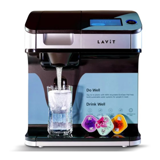
Section 1: The Lavit Beverage Dispenser Overview Lavit Document: TM170915---A... - Page 6 The Lavit Beverage Dispenser is designed to dispense either cold still water, cold sparkling water, or a Lavit beverage, which can be made with either still water or sparkling water, depending on the beverage type. When selecting a Lavit beverage using sparkling water, the beverage can be crafted using a choice of carbonation levels: soft, medium, or full.
- Page 7 90 degrees to the left. Microprocessor Control and Touchscreen The Lavit Dispenser is a microprocessor-controlled beverage and water dispenser with a LCD touch screen providing the user an operating interface and to display process information. The microprocessor controls temperature, water filling, water levels, capsule mixing, water finishing streams, operating of the mix chamber, and dispenser status.
- Page 8 Water Set Up Screen. The Pod ID setting is currently non-- - active for future use. Lavit Button The black Lavit button MUST BE PUSHED TO DISPENSE WATER OR A BEVERAGE. The use of a final dispense button allows the user to verify their drink selection and ensure a cup is placed under the dispense point prior to dispensing.
- Page 9 Bottled Water Installation In addition to a POU installation, the Lavit Dispenser is designed to also work with a 5-- - gallon bottle water supply. A bottled water installation will require the fitting of a Lavit bottle water pump kit, which is supplied separately.
- Page 10 3. DO NOT use any CO bottle not specifically designed to work with the Lavit dispenser. Use only a LAVIT labeled cylinder provided by an authorized Lavit Cylinder Distributor. 4. The Lavit CO cylinder should be properly installed prior to operating the Lavit dispenser.
-
Page 11: Section 2: Installation Installation Overview
The Lavit Beverage Dispenser is designed to be installed in one of three ways. Option 1: A POU connection to a mains water supply, fitted with a Lavit ECO3 filter. Option 2: A 5-gallon bottled water supply using a Lavit pump kit. -
Page 12: Locating The Lavit Dispenser
Locating the Lavit Dispenser 1. Place the dispenser on a firm flat surface, adjacent to the power supply and water supply. 2. Ensure there is an air gap (3 inches) in the rear of the unit. 3. Ensure there is clearance (12 inches) on the right side to open the side door to access the side compartment. -
Page 13: Section 2A: Pou Installation
PRV followed by the check valve and then the shut off valve. As an option a second shut off valve can be installed prior to the PRV to allow the removal of all downstream components. 4. Flush the Lavit ECO3 filter outside of the dispenser to ensure no carbon fines can enter the dispenser. TM170915-B... - Page 14 6. Locate the water pipe that is looped inside the side compartment. Cut the loop. 7. Place the two ends of the pipe into the in and out push fits on the Lavit ECO3 filter. The right side of loop is water in. Mount the filter into the mounting saddle.
- Page 15 13. Wipe the bottle threads and screw the supplied 1.5-pound CO cylinder onto the regulator. DO NOT TURN THE GAS PRESSURE ON AT THIS POINT. Place the cylinder in the side compartment ensuring the side door properly closes. Lavit Document: TM170915---A TM170915-B...
- Page 16 15. The dispenser will self---check on every power up and if OK will go to the LCD home screen and the Lavit Button halo will be red. 16. TO FILL THE DISPENSER WITH WATER, PUSH THE LAVIT BUTTON AND THE DISPENSER WILL START TO FILL. The screen will display a WATER TANK FILLING SCREEN.
- Page 17 An error screen indicating a possible leak will be displayed. To clear the dispenser of this condition, turn the power off and then back on. 21. Push the Lavit Button again and the tanks will then automatically fill to capacity and shut off and the Lavit button halo will be blue.
-
Page 18: Section 2B: Bottled Water Installation
Section 2b: Bottled Water Installation Required Materials and Tools A five-gallon bottle of water Lavit Bottled Water Pump Kit ¼” NSF approved water tubing (black color recommended) Tubing cutter It is recommended that the power cord be connected to a GFI outlet. - Page 19 2. Cut the water pipe loop and place the two ends of the pipe into the Lavit Bottled Water Pump marked in and out. The right-hand side of the loop is water in. 3. Fit the pump into the side compartment using the slots in the bottom of the panel and the screw attachment points.
- Page 20 9. Connect the supplied CO pressure regulator to the inlet tubing. Ensure that the regulator is fully off by turning the knob fully counterclockwise. 10. Screw the supplied 1.5-pound CO cylinder onto the regulator. DO NOT TURN THE GAS PRESSURE ON AT THIS POINT. Place the cylinder in the side compartment ensuring the side door properly closes.
- Page 21 An error screen indicating a possible leak will be displayed. To clear the dispenser of this condition, turn the power off and then back on. Reset the Lavit Pump if necessary (Red Light) by pushing the reset button on the pump. The reset should be green.
-
Page 22: Water Calibration
It is recommended that this feature is Disabled unless a user has asked for colder beverages. 26. Should the 5-gallon bottle run out of water then the Lavit pump kit will sound an alarm and the reset button will turn from green to red. Change the bottle and press the reset button. - Page 23 1. Install the AquaHost Pump Kit according to the instructions provided by the AquaHost manufacturer. 2. Locate the Lavit Beverage Dispenser no more than six (6) feet away from the AquaHost unit. 3. Connect the ¼” water tubing from the outlet of the AquaHost Pump to the water inlet connection at rear of the Lavit dispenser.
- Page 24 6. Connect the supplied CO pressure regulator to the inlet tubing. Ensure that the regulator is fully off by turning the knob fully counterclockwise. 7. Screw the supplied 1.5-pound CO cylinder onto the regulator. DO NOT TURN THE GAS PRESSURE ON AT THIS POINT. Place the cylinder in the side compartment ensuring the side door properly closes.
- Page 25 (Red Light) by pushing the reset button on the pump. The reset should be green. 15. Push the Lavit Button again and the tanks will then automatically continue filling to capacity and shut off and the Lavit Button halo will be blue.
- Page 26 screen. 17. From the Date/Time Screen, enter the Service Menu by pressing the Service Setup icon. 18. From the Service Menu select and make the following choices: Enter MAX TEMP and DISABLE (when disabled the icon will read “Enable”). Set the Filter Timer to DISABLE (when Disabled the icon will read “Enable”). Filter life is not tracked for Bottled Water installations.
- Page 27 Too much water will deliver weak and watery beverages. It is critical that 12-ounce beverages be served each time. To properly calibrate the Lavit Dispenser, three water streams must be calibrated: mix, still, and sparkling. During the calibration process 12 ounces of water should be drawn from the dispenser for each calibration.
- Page 28 17. Replace the blue capsule tray in the mix chamber. 18. Dispense a Lavit Tea, a Lavit still water beverage, and a Lavit sparking water beverage. Use one capsule for all beverage measurements. If available use lemonade, lemon lime, or apple...
- Page 29 STILL WATER OR THE SPARKLING WATER STREAMS AS NECESSARY TO EITHER INCREASE OR DECREASE THE BEVERAGE VOLUME. RE- - - C HECK YOUR BEVERAGE VOLUMES. 21. Once complete, the Lavit Dispenser will retain the settings and 12 ounces of beverages will be served each time. TM170915-B...
- Page 30 Section 3: Operating the Lavit Beverage Dispenser Once the Lavit Beverage Dispenser is properly installed and all water streams have been calibrated, operating the unit is done through the touchscreen and the Lavit Button to the right of the touchscreen.
- Page 31 To Dispense Cold Still Water Pressing and holding the Lavit Button when the halo is BLUE dispenses cold still water. To Dispense Preset Volumes of Still Water and Sparkling Water Press the Water Selections button on the touchscreen. Select a Medium Water, Large Water, or Sparkling Water.
- Page 32 GREEN. PRESSING THE LAVIT BUTTON WHILE FLASHING GREEN TERMINATES THE DISPENSE. To Craft and Dispense an Ice Tea Insert a Lavit Tea Capsule into the Mix Chamber or Select LAVIT BEVERAGES from the HOME SCREEN. If you first selected LAVIT...
- Page 33 Press the Lavit Button when ready to dispense your tea. The Lavit halo will be GREEN. While dispensing the halo will FLASH GREEN. PRESSING THE LAVIT BUTTON WHILE FLASHING GREEN TERMINATES THE DISPENSE. To Craft and Dispense a Still Beverage...
- Page 34 Press the Lavit Button when ready to dispense your still beverage. The Lavit Button halo will be GREEN. While dispensing the halo will FLASH GREEN. PRESSING THE LAVIT BUTTON WHILE FLASHING GREEN TERMINATES THE DISPENSE. To Craft and Dispense a Sparkling Beverage...
- Page 35 Choose one of three available carbonation levels: Soft, Medium, or Full. Press the Lavit Button when ready to dispense your sparkling beverage. The Lavit Button halo will be GREEN. While dispensing the halo will FLASH GREEN. PRESSING THE LAVIT BUTTON WHILE FLASHING GREEN TERMINATES THE DISPENSE.
- Page 36 After displaying the CLEANING SCREEN for a few seconds, the user will be allowed to continue making Lavit beverages of their choice. To clean the Lavit Mix Chamber follow these instructions: 1. Turn off the power to the dispenser using the power switch at the rear of the unit.
- Page 37 9. Remove cup from under the beverage outlet and empty. 10. Wipe down all interior surfaces of the chamber with an anti- - - bacterial wipe. 11. Replace the blue capsule tray and silicone nozzle. Wipe down both with an anti- - - bacterial wipe.
-
Page 38: Section 5: Service Screens
Section 5: Service Screens The SERVICE MENU SCREEN is accessed by selecting the SERVICE ICON on the lower left of the HOME SCREEN. Set the current DATE and TIME by selecting each field to be updated. Toggle up or down to make your entry. - Page 39 The SERVICE SETUP SCREEN is displayed when the correct password is entered. There are six (6) features that are accessed from this screen. Selecting the O3 ICON allows you to set the time that the system will start the ozone disinfection cycle. DEFAULT = 3 am.
- Page 40 DEFAULT = Disabled The WATER SETUP ICON is selected to calibrate the three water streams in your Lavit Dispenser. See the Water Calibration procedure on Page 28. The EMPTY SODA ICON allows the technician to empty the soda tank when required to decommission and move the dispenser.
-
Page 41: Section 6: Information Screens
Section 6: Information Screens During the operation of the Lavit Dispenser various information screens may appear. This screen appears when a sparkling beverage is selected during a low CO2 pressure condition and the CO2 ICON on the HOME SCREEN in RED. - Page 42 Displayed when a Lavit Beverage selection is made and the user has not first inserted a Beverage Capsule. Open mix chamber and insert beverage capsule. Displayed when the beverage carriage fails to reach the HOME POSITION due to buildup of beverage residue in the mix chamber.
-
Page 43: Section 7: Troubleshooting
Section 7: Troubleshooting Potential problems and solutions. Condition Possible Solution Water dripping After the dispensing of a sparkling beverage or sparkling water several continuously drops may occur as the sparkling water in the water line heats up and from the expands. - Page 44 The following four conditions may exist: 1. The CO2 pressure is too high on the CO2 regulator and the high pressure stops the soda pump from refilling the tank. Check that the regulator setting is 3.5 bar. Purge CO2 from the rear of the unit. 2.
- Page 45 bottle. An empty bottle will result in a dry capsule dispense. 3. A faulty mix stream solenoid will cause a dry powder dispense. To check if there is a faulty solenoid, locate on the main PCB the blue plug marked RINSE. Make a beverage. The RINSE solenoid and the MASTER solenoid should come on together and allow water to into the capsule.
- Page 46 Section 8: Decommissioning the Lavit Dispenser Before transporting the Lavit dispenser, it must be drained of all water and the CO2 bottle removed. 1. Turn off the water supply to the machine. Dispense a small amount of still water to relieve the pressure in the inlet line.
- Page 47 Section 9: Service and Repair Removing the Top Cover Page 47 Removing the Side and Rear Panels Page 48 TM170915-B...
- Page 48 2. Remove the two screws in the upper rear of the unit. 3. Pull the top cover off starting at the back and pulling up and forward. 4. Unplug the connector to the touchscreen PCB and unplug the Lavit Button connector. 5. Set top cover aside.
-
Page 49: Removing The Side And Rear Panels
Removing the Side and Rear Panels Left Side Panel There is an internal # 2 Philips screw from behind the panel remove this screw before removing the panel Snap Connection 1. Remove the two rear screws. Note that the bottom rear screw is a longer screw that requires to be used on the bottom rear when reinstalling. - Page 50 Right Side Panel 1. Remove the three rear screws. Not that the bottom rear screw is longer than the others and should be reinstalled in the bottom slot. 2. Remove the three base screws. 3. Remove the side panel screw found near the magnet on the inside front of the side compartment.
- Page 51 Rear Panel 1. Remove power cord and inlet water line. Drain the cold-water tank. Set the drain and drain hold down screw aside. 2. Remove the top cover. (2 top screws) 3. Remove the left and right-side screws. (2 on each side) 4.
- Page 52 Appendices: Schematics and Parts Appendix A: Flow Diagram Appendix B: Electrical Schematic 1 Appendix C: Electrical Schematic 2 Appendix D: Exploded Parts List Appendix E: Wetted Parts List TM170915-B...
- Page 53 Appendix A – Flow Diagram TM170915-B...
- Page 54 Appendix B – Electrical Schematic 1 TM170915-B...
- Page 55 Appendix C – Electrical Schematic 2 TM170915-B...
- Page 56 Appendix D – Exploded Parts Detail TM170915-B...
- Page 58 Appendix D – Exploded Wetted Parts Detail TM170915-B...
- Page 59 TM170915-B...
Need help?
Do you have a question about the LB115 and is the answer not in the manual?
Questions and answers
How do I change the Carbon Cartidge?