Wilo Control SC-Fire Diesel A2P Installation And Operating Instructions Manual
Hide thumbs
Also See for Control SC-Fire Diesel A2P:

Related Manuals for Wilo Control SC-Fire Diesel A2P


Summary of Contents for Wilo Control SC-Fire Diesel A2P
- Page 1 Pioneering for You Wilo-Control SC-Fire Diesel A2P en Installation and operating instructions 4 206 382-Ed.02 / 2016-11-Wilo...
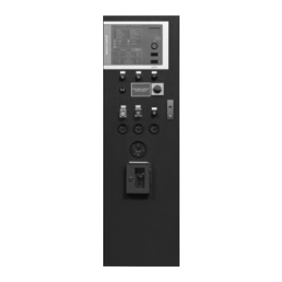
- Page 2 English Fig. 1 WILO SE 11/2016...
- Page 3 English Fig. 1 Installation and operating instructions: Wilo-SC-Fire Diesel A2P...
- Page 4 English Fig. 2 WILO SE 11/2016...
- Page 5 Non-observance may result in death or severe bodily injuries by electric shock. Useful or important information WARNING! Non-observance may result in severe injury. WARNING! Non-observance may result in a risk of damage of material or of the unit. Installation and operating instructions: Wilo-SC-Fire Diesel A2P...
- Page 6 • Highly flammable materials are always to be kept at a safe distance from the product. • Danger from electrical current must be eliminated. Local directives or general directives [e.g. IEC, VDE etc.] and instructions from energy supply companies must be adhered to. WILO SE 11/2016...
-
Page 7: Transport And Interim Storage
The design of this switchgear adheres to the technical regulations defined in the T1-1 of the A2P trademark. The installation, functioning and maintenance are also defined in these technical regulations. The relevant fields of application are habitable buildings, offices, hospitals, hotels, administrative and industrial buildings. Installation and operating instructions: Wilo-SC-Fire Diesel A2P... -
Page 8: Product Information
English 5 Product information 5.1 Type key Example: W-CTRL-SC-F-1x(2)KW-M-FM-ND-D-FR W = WILO CTRL Operation Smart Control = Control unit F = Fire fighting application Number of pumps Rated power range of the diesel motor [kW]: 4.25 – 47.7 kW 66 – 145 kW 197 –... -
Page 9: Description And Function
• Battery selection switch (Fig. 1, pos. 7): selection of the battery for the voltage and current displays (Fig. 1, pos. 4, 5) • Audible warning: Activated in case of an alarm (Fig. 1, pos. 10) Installation and operating instructions: Wilo-SC-Fire Diesel A2P... - Page 10 The chargers and the heating which maintain the temperature of the motor oil constant can be switched on or off via the main switch. To stop the operation, the terminals of connected batteries and the main switch must be disconnected. WILO SE 11/2016...
- Page 11 (Fig. 2, pos. 36, 37). This malfunction causes the diesel motor to start up automatically. In automatic mode, the diesel motor also starts up if the level of the start-up tank is less than 2/3 full. The motor only stops through the intervention of a technician. Installation and operating instructions: Wilo-SC-Fire Diesel A2P...
- Page 12 “OPERATE THE MANUAL START TEST BUTTON IF THE INDICATOR LIGHT IS TURNED ON”. In this case, the corresponding button must be pressed (Fig. 2, pos. 23) to perform the start-up device test. WILO SE 11/2016...
- Page 13 Furthermore, it is possible to adjust the minimal battery voltage in the menu 5.4.1.0. If this voltage is not achieved by one of the connected batteries, an error message is displayed on the screen. Installation and operating instructions: Wilo-SC-Fire Diesel A2P...
- Page 14 (Fig. 1, pos. 3) allows menu selection and the entering of parameters (level 3 access required). To modify the values or to scroll through a menu level, turn the knob and to select and confirm, press it: WILO SE 11/2016...
- Page 15 Availability Return (brief press: a menu level; long press: main screen) EXPERT menu 1. Notification: not connected 2. Notification: display value – no entry possible Active/unlocked Service menu Parameters Information Malfunction Reset malfunction Installation and operating instructions: Wilo-SC-Fire Diesel A2P...
- Page 16 Actual value Sensor signal Measurement sensor range Electric Follow-up time Operating mode/application Stand-by Operational data Switchgear data: Controller type; ID number; software/firmware Operating hours Pump operating hours Switchgear operating cycles Pump operating cycles Communication Output parameters SSM parameters WILO SE 11/2016...
- Page 17 Motor oil Diesel Thermostat temperature of the motor Diesel (Temperature of the water) for cooling Diesel Belt rupture Diesel Start-up interruption Electric Pressure Electric Power supply (mains) Electric Voltmeter Ammeter Cut-in star-delta Electric Installation and operating instructions: Wilo-SC-Fire Diesel A2P...
- Page 18 Reset to the factory setting Alarm counter Maintenance interval Reset Motor rotation speed Diesel Definition of the motor rotation speed Diesel Minimum rotation speed for the signal “motor in operation” Diesel Start-up counter reset Diesel Manual Diesel Commissioning Diesel WILO SE 11/2016...
- Page 19 The menu structure of the control system has 4 levels. Navigation in the individual menus as well as the parameter input are described in the example of the modification of the minimum battery voltage (level of access 3 required): Installation and operating instructions: Wilo-SC-Fire Diesel A2P...
- Page 20 “Services” menu To access level 3 an access code must be 0…9999 entered. After 5 minutes of inactivity on HMI or after a main supply malfunction, access is blocked and the code must be re-entered. “Malfunctions” menu WILO SE 11/2016...
- Page 21 Menu unlocked with the correct access code The EXPERT menu contains other settings which enable a detailed configuration of the switchgear. Installation and operating instructions: Wilo-SC-Fire Diesel A2P...
- Page 22 “finished”. Minimum rotation speed from which the 200 … 800 … 3000 controller deems that the “motor is in operation”. The parameter menu for all timer parameters influencing the operation. WILO SE 11/2016...
- Page 23 Start-up delay in case of pressure switch 1 … 10 activation Start-up delay in case of float switch 1 … 10 activation Activation delay from the malfunction 0 … 3 … 5 “Empty fuel tank” Installation and operating instructions: Wilo-SC-Fire Diesel A2P...
- Page 24 No bus (no active bus), Modbus, BACnet Pump menu Display of the automatic mode status: ON or OFF Remarks: This information is the image of the change-over switch status on the front of the cabinet. Information menu Service parameters WILO SE 11/2016...
- Page 25 English Battery voltage Instantaneous voltage battery A Instantaneous voltage battery B Load currents Instantaneous load current battery A Instantaneous load current battery B Installation and operating instructions: Wilo-SC-Fire Diesel A2P...
- Page 26 Total start-up attempt counter from battery A Total start-up attempt counter from battery B Status of sensors Status of pressure switch Contact open Contact closed Status of start-up tank float switch (low level) Contact open Contact closed WILO SE 11/2016...
- Page 27 Status of the thermo contact of the cooling water of the diesel motor Contact open Contact closed Values of the sensors Display of the oil pressure Remarks: At menu 5250 this sensor is deactivated as not installed in the system. Installation and operating instructions: Wilo-SC-Fire Diesel A2P...
- Page 28 Temperature of the cooling water (external) Remarks: This sensor is not installed in the system. Rotation speed menu Display of instantaneous rotation speed of the diesel motor Display of the minimum rotation speed to deem that the “motor is in operation” WILO SE 11/2016...
- Page 29 Total hour counter of operation of the diesel motor since the last start-up Number counter of cabinet power ups Remarks: Activation of the main switch or connection of batteries Number counter of pump start-ups Installation and operating instructions: Wilo-SC-Fire Diesel A2P...
- Page 30 English System characteristics System type SC Diesel APSAD Serial number display Remarks: Text scrolling Software version display Firmware version display Adjustments WILO SE 11/2016...
- Page 31 English Communication Modbus Baud delivery rate 19.2 38.4 76.8 Slave address 1 … 4 … 247 Parity Even No (none) Stop bits Installation and operating instructions: Wilo-SC-Fire Diesel A2P...
- Page 32 English BACnet Baud delivery rate 19.2 38.4 76.8 1 … 4 … 255 Slave address Parity Even No (none) Stop bits 0 … 24 … 9999 BACnet Device Instance ID WILO SE 11/2016...
- Page 33 0 … 3000 (in ohms) temperature of 10 °C 5.2.6.9 Remarks: The adjustment of the resistance profile continues in the menus 5.2.6.2 to 5.2.6.9. Activation of the monitoring of belt failure Forced cut-in of battery charger Installation and operating instructions: Wilo-SC-Fire Diesel A2P...
- Page 34 And the countdown before duty cycling is reset to 0, visible on the main screen. Limit values Minimum battery voltage 0 … 30 Control of the commissioning Control of the commissioning start-up Finished, Start Remarks: Menu dedicated to the commissioner. Malfunction messages WILO SE 11/2016...
- Page 35 Access to the parameterisation of the cabinet Designation of the cabinet Adjustment of the serial number: 0…9999 Adjustment of the first 4 numbers of the serial number These numbers are adjusted in the factory and cannot be modified. Installation and operating instructions: Wilo-SC-Fire Diesel A2P...
- Page 36 By pressing the red button, the symbol “factory” flashes, turn the red button to the right, the symbol “reverse arrow” appears, press the button a second time to launch the resetting of the cabinet to factory configuration. Alarm menu WILO SE 11/2016...
- Page 37 Enter the activation code, for example, to activate a field bus connection. Modification of access code to level 3: To reset the access code, please call the technical service. Operational data of the menu reset Installation and operating instructions: Wilo-SC-Fire Diesel A2P...
- Page 38 1 Resetting to zero of the total hour counter of operation time of battery 2 Maintenance and repair menu Activation/deactivation of the maintenance interval Adjustment of the duration in days for the 0…92…1000 maintenance interval WILO SE 11/2016...
- Page 39 RIA menu Activation/deactivation of the RIA application: Protected access: To gain access, please call the technical service. Activation/deactivation of the application of the hydrants: Once access has been granted by the technical service. Installation and operating instructions: Wilo-SC-Fire Diesel A2P...
- Page 40 • “BUZZER OFF” (Fig. 2, pos. 18) This button allows an audible signal emitted in case of alarm to be cleared separately (level of access 1 required). As soon as a new malfunction arises, the buzzer signal sounds once again. WILO SE 11/2016...
- Page 41 The measurement of the differential pressure at the filter level has detected a clogged filter. This malfunction is thus signalled by the LED turning on red. “STARTER MALFUNCTION” (Fig. 2, pos. 7) As soon as the switchgear no longer receives a response from the starter, the LED turns on red. Installation and operating instructions: Wilo-SC-Fire Diesel A2P...
- Page 42 “BATTERY CHARGER 1/2 MALFUNCTION” (Fig. 2, pos. 28, 29) The connection voltage of the battery chargers is monitored. Furthermore, any absence of error or communication malfunction is checked. As soon as a malfunction occurs, the LED turns on yellow. WILO SE 11/2016...
-
Page 43: Installation And Electrical Connection
Local directives or general directives [e.g. IEC] and instructions from local energy supply companies must be adhered to. 7.1 Installation Install the switchgear/unit in a dry location. Protect the place of installation from direct exposure to sunlight. Installation and operating instructions: Wilo-SC-Fire Diesel A2P... - Page 44 7.2.3 Connection of the malfunction signals/run signals A signal can be withdrawn via a potential-free contact on the terminal strip for the malfunction/running messages in order to signal a malfunction/operation (see wiring diagram). Potential-free, contact load max. 250 V ~/1 A WILO SE 11/2016...
- Page 45 The signal output is activated as soon as the diesel motor has started and when the rotation speed increased by the rotation speed sensor has reached or exceeded the pre-set value for a “motor in operation” (menu 1.2.1.3). “START-UP FAILURE” The output signal is activated following six consecutive failed start-up attempts. Installation and operating instructions: Wilo-SC-Fire Diesel A2P...
- Page 46 “START-UP VIA PRESSURE SWITCH 1/2” green/yellow “PRESSURE SWITCH LINE 1/2 MALFUNCTION” Table 4: Malfunction signals and run signals Warning! Danger of electric shock! There is a potentially fatal voltage on these terminals, even when the main switch is turned off. WILO SE 11/2016...
- Page 47 This work must only be carried out by qualified personnel! We recommend that you have the switchgear commissioned by Wilo customer service. Before switching on for the first time, the on-site wiring must be checked, in particular the earthing.
-
Page 48: Maintenance
It is possible to clear the malfunction by pushing the button “CLEAR FAULT” (Fig. 2, pos. 20) (level of access 2 required) or by following the steps described in the menu 6.1.0.0 (level of access 3 required): WILO SE 11/2016... - Page 49 Connection with charger 2 Check connection with the charger of interrupted Request customer service battery 2 E54.3 Incorrect transfer of data Malfunction on the data line Request customer service from the charger of battery 1 Installation and operating instructions: Wilo-SC-Fire Diesel A2P...
- Page 50 Pinion circuit interrupted No response from starter Check the fuse pinion Request customer service E136.0 Start-up failure 6 failed start-up attempts Request customer service E137.0 Belt rupture No alternator voltage Check the V-belt and replace it in necessary WILO SE 11/2016...
-
Page 51: Spare Parts
11 Spare parts Spare parts may be ordered via a local specialist retailer and/or Wilo customer service. To avoid queries and incorrect orders, all data on the rating plate should be submitted with each order. Subject to change without prior notice... - Page 52 Battery voltage h = 72 h Time required for independent operation 222 Ah required 111 Ah required on 2 batteries on 2 batteries 2 x 111 Ah 2 x 56 Ah under 12 V under 24 V WILO SE 11/2016...
- Page 53 DI (Differential pressure sensor, closed if the filter malfunction is not clogged) Aeration vent malfunction DI (position contact, closed if the vents are open) Technical room DI (Thermostat, open when the temperature is temperature malfunction too low) Installation and operating instructions: Wilo-SC-Fire Diesel A2P...
- Page 54 DO (NC) DO (NO) Risk of failure (2 contacts no/nc) DO (NC) DO (NO) Automatic mode deactivated on battery 1 (2 contacts no/nc) DO (NC) Automatic mode DO (NO) deactivated on battery 2 (2 contacts no/nc) DO (NC) WILO SE 11/2016...
- Page 55 Electric switch off of the Control voltage output (for the electric shut-off diesel motor device, in 12 or 24 V DC) Performance input (load current between the Load current (alternator) generator and switchgear during pump operation) Installation and operating instructions: Wilo-SC-Fire Diesel A2P...
- Page 56 Low water level Start-up pinion malfunction V-belt rupture Oil pressure Cooling liquid temperature Oil temperature Analogue inputs External water temperature Fuel level Motor rotation speed (sensor) Motor rotation speed (alternator) Motor activated Activated outputs Cooling bypass valve WILO SE 11/2016...
- Page 57 Battery 1 Power supply input performance Battery 2 Load current of the diesel motor Oil pre-heating Starter - Starting current Output performance Starter - Auxiliary voltage Electric switch off of the diesel Mass Installation and operating instructions: Wilo-SC-Fire Diesel A2P...
- Page 58 English Details of the terminal blocks of the PCB master/diesel slave WILO SE 11/2016...
- Page 59 RS485 A_L charger Internal bus: Battery 1 RS485_B_L RS485_B_L charger Internal bus: Battery 2 RS485: Output Modbus or RS485_A_R RS485_A_R charger Bacnet RS485: Output Modbus or Internal bus: Battery 2 RS485_B_R RS485_B_R Bacnet charger Installation and operating instructions: Wilo-SC-Fire Diesel A2P...
- Page 60 Field Bus5 Field Bus6 Field Bus6 Field Bus7 Field Bus7 Field Bus8 Field Bus8 X600 Used for: X600 Used for: Start-up tank float switch - Digital In 0 Pressure switch no. 1 Digital In 0 Malfunction low level WILO SE 11/2016...
- Page 61 (contact available) Relay 0 NC Relay 0 NC Relay 0 COM 24 V DC Relay 0 COM 24 V DC Relay 1 NO Motor stopped Relay 1 NO Automatic stop on battery 2 Installation and operating instructions: Wilo-SC-Fire Diesel A2P...
- Page 62 Relay 8 NO Relay 8 NO (Automatic) Start-up battery 2 Relay 9 NO Relay 9 NO (Manual) Relay 8-11 COM 12 V DC Relay 8-11 COM Relay 10 NO Relay 10 NO Relay 11 NO Relay 11 NO WILO SE 11/2016...
- Page 63 WILO SE Nortkirchenstraße 100 D-44263 Dortmund Germany T +49(0)231 4102-0 F +49(0)231 4102-7363 wilo@wilo.com Pioneering for You www.wilo.com...
Need help?
Do you have a question about the Control SC-Fire Diesel A2P and is the answer not in the manual?
Questions and answers