Advertisement
Quick Links
Wilo-ER 2/ ER 3-4
D
Einbau- und Betriebsanleitung
GB
Installation and Operating Instructions
F
Notice de montage et de mise en service
NL
Montage- en bedieningsvoorschriften
E
Instrucciones de instalación y servicio
I
Istruzioni di montaggio, uso e manutenzione
H
Beépítési és üzemeltetési utasítás
PL
Instrukcja montażu i obsługi
CZ
Návod k montáži a obsluze
RUS
montaΩu
Instrukciä po
i qkspluataciœ
Advertisement

Related Manuals for Wilo ER 2


Summary of Contents for Wilo ER 2
- Page 1 Wilo-ER 2/ ER 3-4 Einbau- und Betriebsanleitung Beépítési és üzemeltetési utasítás Installation and Operating Instructions Instrukcja montażu i obsługi Notice de montage et de mise en service Návod k montáži a obsluze Montage- en bedieningsvoorschriften montaΩu Instrukciä po i qkspluataciœ...
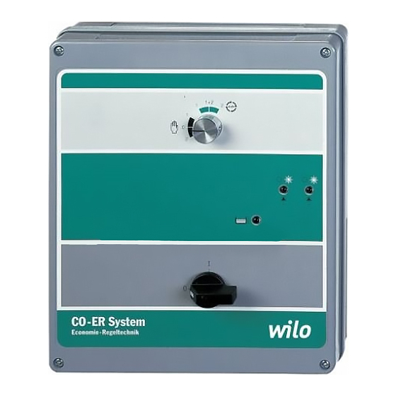
- Page 2 CO-ER System Economy Regeltechnik Fig. 1...
- Page 3 Fig. 2...
- Page 4 Fig. 3...
- Page 5 Fig. 4...
- Page 6 Fig. 5 Fig. 6...
- Page 7 1. Allgemeines ........1.
- Page 8 1. V‰eobecné informace ......28 2. Bezpeãnost ........28 3.
- Page 9 ´ daki cihazlarí ´ n takibi standartlara vygun oldug ˇ unu temin ederiz: Elektromanyetik Uyumluluk 89/336/EWG i.d.F., 92/31/EWG, 93/68/EWG Özellikle kullaní ´ lan Normlar EN 50 081-1, EN 50 082-1 WILO AG Nortkirchenstraße 100 Quality Management 44263 Dortmund · Germany...
-
Page 10: Safety Notes
4.2 Unit front panel (Fig. 1) Switch unit for the automatic control of low capacity pump units The ER 2/ER 3-4 control unit serves to automatically control a multi- consisting of 2 to 4 pumps in conjunction with pump set. The unit front panel contains the following switches or sig- –... -
Page 11: Maintenance
‘Pump Duty Cycling’ has been provided, meaning that on each new start of the plant the next successive pump assumes the base-load All functional adjustments on the ER 2/ER 3-4 control unit as laid out function. Duty changeover also takes place when one or more in Charts I and II must have been set prior to initially starting the pump(s) are continously running (approx. - Page 12 ENGLISH Chart I: Functions of potentiometers and hook switches (Fig. 2/3) Switch/Pot. Functions Potentiometer for FLC-settings: P1 for No. 1 pump P2 for No. 2 pump P3 for No. 4 pump P4 for No. 3 pump P8 to set pump stop time delay (0 – 2 min) P9 to set pump stop time delay on low water cut-out (0 –...
- Page 13 ✍...
Need help?
Do you have a question about the ER 2 and is the answer not in the manual?
Questions and answers