
Subscribe to Our Youtube Channel
Related Manuals for Wilo Control MS-L


Summary of Contents for Wilo Control MS-L
- Page 1 Pioneering for You Wilo-Control MS-L en Installation and operating instructions · 2552612 • Ed.02/2022-05...
- Page 2 Control MS-L https://qr.wilo.com/1393...
- Page 3 Fig. 3: Control MS-L1... 1 2 3 4 5 6 7 8 Seconds 1/L1 3/L2 5/L3 7 8 9 1 2 3 4 5 6 2/T1 4/T2 1 2 3 4 3~400V 50/60Hz L1L2L3N min. 12 VDC, 10 mA max. 250 VAC, 1 A 1 2 3 4 1~230V 50/60Hz ON / OFF...
- Page 4 Fig. 3: Control MS-L1...-O 1 2 3 4 5 6 7 8 Seconds 7 8 9 1 2 3 4 5 6 3~400V 50/60Hz 1 2 3 4 min. 12 VDC, 10 mA L1L2L3N max. 250 VAC, 1 A 1~230V 50/60Hz 1 2 3 4 ON / OFF ON /...
- Page 5 Fig. 3: Control MS-L1...-LS 1 2 3 4 5 6 7 1 2 3 Seconds Sensor + ln 7 8 9 1 2 5 3~400V 50/60Hz L1 L2 L3 PE min. 12 VDC, 10 mA ON / OFF max. 250 VAC, 1 A NW21/NW22 1~230V 50/60Hz...
- Page 6 Fig. 3: Control MS-L2... 1 2 3 4 5 6 7 Seconds 1 2 3 4 5 6 7 L1 L2 L3 N 1/L1 3/L2 5/L3 Alarm 2/T1 4/T2 6/T3 1 2 3 4 3~400V 50/60Hz min. 12 VDC, 10 mA L1 L2 max.
- Page 7 Fig. 3: Control MS-L2...-O 1 2 3 4 5 6 7 Seconds 1 2 3 4 5 6 7 L1 L2 L3 N Alarm 3~400V 50/60Hz 1 2 3 4 min. 12 VDC, 10 mA max. 250 VAC, 1 A L1 L2 L3 N 1~230V 50/60Hz 1 2 3 4...
- Page 8 Fig. 3: Control MS-L2...-LS 1 2 3 1 2 3 4 5 6 7 Seconds 1 2 3 4 5 6 7 L1 L2 L3 N Alarm Sensor + ln 3~400V 50/60Hz L1 L2 L3 PE min. 12 VDC, 10 mA ON / OFF max.
-
Page 9: Table Of Contents
Commissioning in explosive atmospheres ...... 29 Connection of signal transmitters within potentially ex- plosive atmospheres............ 29 Activating the device ............ 29 Installing the rechargeable battery ........ 30 Check the direction of rotation of the connected pumps .................... 30 Installation and operating instructions • Wilo-Control MS-L • Ed.02/2022-05... -
Page 10: General Information
All rights reserved. Subject to change Wilo shall reserve the right to change the listed data without notice and shall not be liable for technical inaccuracies and/or omissions. The illustrations used may differ from the ori- ginal and are intended as an example representation of the device. -
Page 11: Personnel Qualifications
• Have read and understood the installation and operating in- structions. Personnel must have the following qualifications: • Electrical work: A qualified electrician must carry out the elec- trical work. Installation and operating instructions • Wilo-Control MS-L • Ed.02/2022-05... -
Page 12: Electrical Work
The user must notify the person in charge of every fault or ir- regularity immediately. • In case of damage to the product or connection cable, switch off the product immediately. Installation and operating instructions • Wilo-Control MS-L • Ed.02/2022-05... -
Page 13: Maintenance Tasks
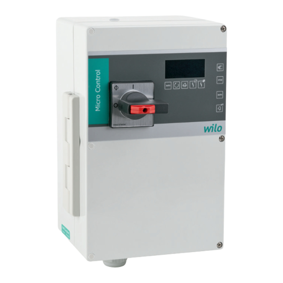
Microcontroller-controlled switchgear for control of one or two pumps. Separate main switch for directly switching the switchgear on and off. NOTICE! The MS-L...-LS and MS-L...-O ver- sions do not have a main switch! Fig. 1: Control MS-L 1 Installation and operating instructions • Wilo-Control MS-L • Ed.02/2022-05... -
Page 14: How It Works
24 V DC Housing material UV-resistant polycarbonate *The date of manufacture is stated in accordance with ISO 8601: JJJJWww • JJJJ = year • W = abbreviation for week • ww = calendar week Installation and operating instructions • Wilo-Control MS-L • Ed.02/2022-05... -
Page 15: Inputs And Outputs
Max. number of pumps that can be connected Max. permissible rated power (P ) per pump Activation type of connected pump: Direct Mains connection version: • Without: 3P+N+PE • T4: 3P+PE Installation and operating instructions • Wilo-Control MS-L • Ed.02/2022-05... -
Page 16: Operation On Electronic Start-Up Controllers
• Clean the switchgear after storage. • If there has been water ingress or condensation has formed, have all the electronic com- ponents tested for correct function. Contact customer service! Installation and operating instructions • Wilo-Control MS-L • Ed.02/2022-05... -
Page 17: Installation
NOTICE! If the cover does not close correctly, the protection class is compromised! Close the cover and fasten it with the screws. Installation and operating instructions • Wilo-Control MS-L • Ed.02/2022-05... -
Page 18: Electrical Connection
▶ Switchgear installed. Next steps: Connect the power supply, pumps and signal transmitters. NOTICE! The Control MS-L...-LS is pre-wired to the lifting unit. 6.4.3 Level control Control MS-L.../MS-L...-O Install a level control device for the automatic control of the pumps. Connect one float switch per pump for this purpose. - Page 19 Setting the switching points − − • − − • • • = available , − = not available • DIP on: DIP top (ON) • DIP off: DIP bottom (OFF) Installation and operating instructions • Wilo-Control MS-L • Ed.02/2022-05...
- Page 20 3~400 V at the factory. Install the two cable bridges on the mains terminal strip for connection to the mains voltage 1~230 V. Incorrect connection destroys the switchgear! The switchgear Control MS-L … -LS is only suitable for the stated mains voltage! Control MS-L … : Mains connection 1~230 V, with main switch Insert the connection cables laid by the customer through the threaded cable glands and secure.
- Page 21 Mains connection is established by inserting the plug into a socket: • 1~230 V: Shock-proof socket (Type E or Type F) or CEE32 socket • 3~400 V: CEE16-socket Install the socket in an overflow-proof manner in a radius of 1 m from the switchgear. Installation and operating instructions • Wilo-Control MS-L • Ed.02/2022-05...
- Page 22 Switch on pump 2: Set DIP 7 to “ON”. Fig. 10: DIP switch 2: Switch on pumps 6.5.7 Connection, thermal motor monit- NOTICE oring Do not apply external voltage! An external voltage which is applied destroys the component. Installation and operating instructions • Wilo-Control MS-L • Ed.02/2022-05...
- Page 23 Sensor + ln Fig. 12: Terminal strip sensors: Level detec- tion connection 6.5.9 High water alarm connection NOTICE Do not apply external voltage! An external voltage which is applied destroys the component. Installation and operating instructions • Wilo-Control MS-L • Ed.02/2022-05...
- Page 24 There is a risk of fatal injury! • Disconnect external power supply before any work! • Electrical work must be carried out by a qualified electrician! • Observe local regulations! Installation and operating instructions • Wilo-Control MS-L • Ed.02/2022-05...
-
Page 25: Functions
1 2 3 4 5 6 7 • DIP 5 “ON”: ½ year service interval • DIP 4 and 5 “ON”: 1 year service interval Fig. 18: DIP switch 2: Service interval indicator Contact customer service to reset the counter. Installation and operating instructions • Wilo-Control MS-L • Ed.02/2022-05... -
Page 26: Operation
LEDs on the front 7.1.1 Main switch The standard version is switched on and off using a main switch. The main switch can be secured against unauthorised switching on and off using a lock! Installation and operating instructions • Wilo-Control MS-L • Ed.02/2022-05... - Page 27 If a button is pressed when the key lock is active, all LEDs light up for 2 sec. • The buzzer can be switched off and the collective fault signal (SSM) deactivated when the key lock is active. • Acknowledgement of error messages is not possible! Installation and operating instructions • Wilo-Control MS-L • Ed.02/2022-05...
-
Page 28: How It Works
Provide installation and operating instructions at the switchgear or at a place specially Operator responsibilities reserved for it. • Make the installation and operating instructions available in a language the personnel can understand. Installation and operating instructions • Wilo-Control MS-L • Ed.02/2022-05... -
Page 29: Commissioning In Explosive Atmospheres
Follow-up time set. Turn the main switch to the “1/ON” position. NOTICE! Switchgear without main switch: Establish power supply by means of mains isolator! Switchgear starts. All LEDs light up for 2 s. Installation and operating instructions • Wilo-Control MS-L • Ed.02/2022-05... -
Page 30: Installing The Rechargeable Battery
(clockwise or counter-clockwise)! Observe the installation and operating instructions of the pumps. Perform a test run to check the direction of rotation of the pumps. CAUTION! Material damage! Perform the test run under the prescribed operating conditions. Installation and operating instructions • Wilo-Control MS-L • Ed.02/2022-05... -
Page 31: Start Automatic Mode
Turn main switch to the “0/OFF” position. ⇒ The “on” LED goes out. ⇒ The “auto” LED goes out. Secure the main switch against being activated by unauthorised persons (e.g. lock main switch) ▶ Switchgear switched off. Installation and operating instructions • Wilo-Control MS-L • Ed.02/2022-05... -
Page 32: Removal
Check electrical-mechanical components for wear Have electrical-mechanical components checked for wear by an electrician. If wear is as- certained, have the affected components replaced by an electrician or by the Wilo Cus- tomer Service. Installation and operating instructions • Wilo-Control MS-L • Ed.02/2022-05... -
Page 33: Faults, Causes And Remedies
Contact customer service to have the faulty sensor re- placed. The last fault is stored retentively in the fault memory. The corresponding LED lights up 11.5 Fault memory when the fault is retrieved. Installation and operating instructions • Wilo-Control MS-L • Ed.02/2022-05... -
Page 34: Further Steps For Troubleshooting
Hand over these products at designated, certified collection points only. • Observe the locally applicable regulations! Please consult your local municipality, the nearest waste disposal site, or the dealer who sold the product to you for information on proper disposal. See www.wilo‑recycling.com for more information about recycling. Appendix 13.1... - Page 35 System impedance in ohm Connections/h 0.2788 0.2126 0.1915 0.2000 0.1292 0.1164 0.1559 0.0889 0.0801 3~400 V, 4-pole, direct starting Power in kW System impedance in ohm Connections/h 0.2330 0.2100 0.2090 0.1380 0.1240 0.1480 0.0830 0.0740 Installation and operating instructions • Wilo-Control MS-L • Ed.02/2022-05...
- Page 40 Local contact at www.wilo.com/contact WILO SE Wilopark 1 44263 Dortmund Germany T +49 (0)231 4102-0 T +49 (0)231 4102-7363 wilo@wilo.com Pioneering for You www.wilo.com...
Need help?
Do you have a question about the Control MS-L and is the answer not in the manual?
Questions and answers