Subscribe to Our Youtube Channel
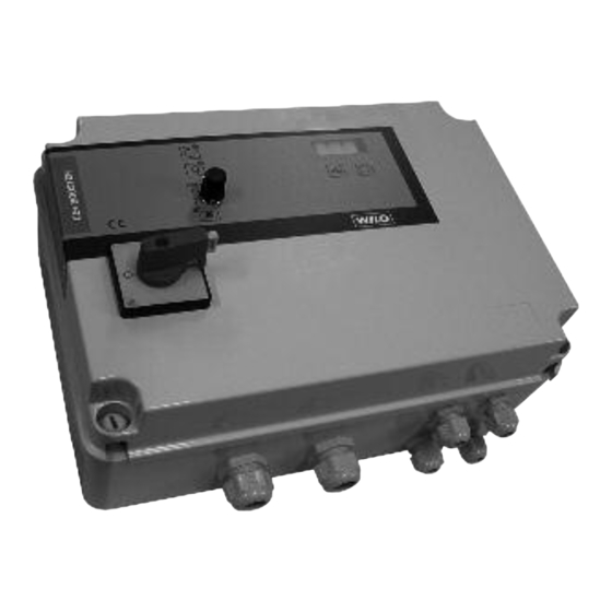
Summary of Contents for Wilo CONTROL BOX CE+ WeH
- Page 1 Wilo-CONTROL BOX CE+ WeH/WeV Notice de montage et de mise en service Installation and operating instructions...
- Page 2 Fig. 1a Fig. 1b...
- Page 3 Fig. 2 Fig. 3 Senso InSp 0-10 0-16...
- Page 4 Fig. 4 Inhibition 230 VAC Filling +24V Burner 4-20 mA Fig. 5...
- Page 5 Notice de montage et de mise en service Installation and operating instructions Istruzioni di montaggio, uso e manutenzione Instrucciones de instalación y funcionamiento Manual de instalação e funcionamento...
- Page 6 Elle peut également entraî- de pression. ner la suspension de tout recours en garantie. Il est utilisé pour la mise et le maintien en pression WILO SE 09/2011...
-
Page 7: Caractéristiques Du Produit
5.1 Dénomination 3 Afficheur 3 x 7 segments 4 Voyant marche par pompe WILO CE+ WEV/WEH 1 x 15 5 Voyant défaut pompe par pompe 6 Commutateur rotatif 3 positions : Manuel – 0 Designation de la gamme de coffret (reset) –... - Page 8 • reset automatique du défaut. - courant moteur inférieur à 0,5A. - manque d’eau Phase manquante - pression trop forte Le système est protégé si une ou plusieurs phases - pression trop faible du réseau sont manquantes : WILO SE 09/2011...
- Page 9 - Err-LEA : défaut de surconsommation d’eau fuite est à votre disposition à l’intérieur du coffret de possible commande. - Err-Sen : câble capteur pression coupé ATTENTION ! Ne pas oublier de raccorder la borne terre ! WILO SE 09/2011...
-
Page 10: Mise En Service
Nous vous conseillons de confier la première mise en service de votre surpresseur à un agent Capteur de pression du service après-vente WILO le plus proche de Connecter correctement le capteur aux bornes chez vous ou tout simplement à notre centrale (Fig. -
Page 11: Maintenance
- Régler le seuil de détection de courant de chaque moteur à l'aide des potentiomètres dédiés (Fig. 1, rep. 9 " I> ") en positionnant les flèches sur le courant nominal moteur plaqué et majorée de 10%. WILO SE 09/2011... - Page 12 Afin d’éviter des erreurs, veuillez spécifier les données figurant sur la plaque signalétique de la pompe lors de toute commande. La catalogue de pièces détachées est disponible à l’adresse : www.wilo.com. Sous réserve de modifications technique ! WILO SE 09/2011...
- Page 13 Failure to comply with the safety precautions HVAC loop in high-rise apartments, hospitals, could result in personal injury or damage to the offices and industrial buildings. pump or installation. It could also invalidate any claims for damages. WILO SE 09/2011...
-
Page 14: Technical Data
Fig. 2 5.1 Type key 1 Led power ON 2 Led dry-running WILO CE+ WEV/WEH 1 x 15 3 Display 3 x 7 segments 4 Led pump ON (one per pump) Designation of the control box range 5 Led pump fault (one per pump) Number of pumps monitored 6 3-position rotary switch (one per pump) : Hand –... - Page 15 6.2.2 Inputs/Outputs FIG. 4 power cables against short-circuit. On this fault 1 Pressure input (4 – 20mA) : an analog input on type, the electronic switches directly on another the electronic part allows the connection of a WILO SE 09/2011...
-
Page 16: Installation And Electrical Connection
Right connecting of the sensor to the terminals cation. (FIG. 4, pos. 1) according to the control box elec- 10Too low pressure: too low pressure fault indica- tric diagram: tion. - The sensor supply is connected to the terminal +24V. WILO SE 09/2011... - Page 17 We recommend that the system is first commis- pressure alarm with the dip-switch (Fig. 3, pos. 2 sioned by the WILO customer service. Ask your "InsP "). “On” the pump will continue in case of dealer, the nearest WILO agent or contact our low pressure alarm, “off”...
-
Page 18: Spare Parts
Review settings of PLo and PHi values pressure PLo and stopping pressure PHi too small 11. Spare parts All spare parts must be ordered through WILO Customer Services. In order to avoid any mistakes, please specify the name plate data for orders. - Page 19 If the above mentioned series are technically modified without our approval, this declaration shall no longer be applicable. Si les gammes mentionnées ci-dessus sont modifiées sans notre approbation, cette déclaration perdra sa validité. Dortmund, 31.01.2009 Erwin Prieß WILO SE Quality Manager Nortkirchenstraße 100 44263 Dortmund Germany Document: 2096963.2...
- Page 20 Bu cihazın teslim edildi i ekliyle a a ıdaki standartlara uygun oldu unu teyid ederiz: EN 60439-1, Elektromanyetik Uyumluluk 2004/108/EG EN 61000-6-1, 2004/108/EG Alçak gerilim direktifi 2006/95/EG EN 61000-6-2, EG–2006/95/EG EN 61000-6-3, Kısmen kullanılan standartlar: EN 61000-6-4. Erwin Prieß WILO SE Quality Manager Nortkirchenstraße 100 44263 Dortmund Germany...
- Page 21 ) ! % 8:<43:-2/7;<:+D/ 8:<6=7. /:6+7A & ?358 ?358 -86 ??? ?358 ./ "! ) ! % ) ! % ) ! % ) ! % (/:<:3/,;,G:8 +6,=:1 (/:<:3/,;,G:8 :/;./7 (/:<:3/,;,G:8 %<=<<1+:< (/:<:3/,;,G:8 G;;/5.8:0 /36 %<:822+=;/ :+74/7:371 /:<3-2;<:+D/ )/;<:371 +6,=:1 /;;/5;.8:0 /87,/:1 35./7...
- Page 22 ) " % !:<>64<.309=><,H0 :<>8?9/ 0<8,9C & A47: A47: .:8 AAA A47: .:8 !$ / #( &# ( $# ! %?-=4/4,<40= & #( # &$ ( )# &- + (. &! # ) " % %"! ) " <@,>=6, / : : ) "...


Need help?
Do you have a question about the CONTROL BOX CE+ WeH and is the answer not in the manual?
Questions and answers