
Subscribe to Our Youtube Channel
Related Manuals for Kongskilde VM-1


Summary of Contents for Kongskilde VM-1
- Page 1 ORIGINAL INSTRUCTIONS - according to Directive 2006/42/EC, Annex I 1.7.4.1 VM-1 VM-2 VM-3 Other Hay Equipment OPERATOR'S MANUAL Part Number 91821643 1st edition English July 2022...
-
Page 2: Table Of Contents
Implement orientation (for VM-1 models) ........ - Page 3 Starting the unit Connection to the tractor ............. . . 4-4 Front Power Take-Off (PTO) drive shaft –...
- Page 4 Planet gear oil change (for VM-1 models) ........
- Page 5 Technical data (for VM-1 models) ........
-
Page 7: General Information
Directives 2006/42/EC and 2014/30/EU. Always use genuine KONGSKILDE Service Parts or parts that match at least the same quality, reliability and func- tionality as the equivalent original Service Parts when you service and repair your implement and do not modify your implement without a written permission of the manufacturer. - Page 8 KONGSKILDE is not liable for any damage caused by the use of ''non-genuine” parts and accessories. Rely on your authorized dealer to supply you with genuine KONGSKILDE parts only. These parts are covered by our warranty and will give you the best performance.
- Page 9 It is prohibited to carry out any modifications to the implement unless specifically authorized, in writing, by a KONGSKILDE representative. CLEANING YOUR IMPLEMENT When you use a high pressure washer, do not stand too close to the implement and avoid directing the jet at electronic components, electrical connections, breathers, seals, filler caps, and so on.
-
Page 10: Intended Use
1 - GENERAL INFORMATION Intended use The feeder is intended for mixing components for animal structions as well as common rules concerning technical feed and for dispensing the finished feed mixture. safety, working practices and road safety. Also read the spare parts catalog and use original spare parts. -
Page 11: Prohibited Usage
No parts must be fitted to this implement, which have not Any other use beyond the intended use is regarded as been released by KONGSKILDE. They might affect the misuse and requires the authorization of the manufac- implement operation, safety of the user or other people, turer. -
Page 12: Electro-Magnetic Compatibility (Emc)
• Ensure that each piece of non‐ KONGSKILDE equipment fitted to the machine bears the CE mark. • The maximum power of emission equipment (radio, telephones, etc.) must not exceed the limits imposed by the national authorities of the country where you use the machine. -
Page 13: Manual Scope And Required Training Level
KONGSKILDE during normal operation, routine service, and maintenance. Periodic service consists of activities that are necessary to maintain the expected life of the KONGSKILDE ma- This manual does not contain all the information that re- chine. These activities have defined intervals. - Page 14 1 - GENERAL INFORMATION must demonstrate the ability to operate and service the aging depending on the kind of shipment and the related KONGSKILDE machine in a correct and safe manner. procedure to assemble the received components. Additional documents When required, the machine is delivered with an assem-...
-
Page 15: Product Identification Number (Pin)
The Product Identification Number (PIN) is a serial num- ber that identifies the implement. The serial number, model, and other specifications, are on the PIN plate. Provide your KONGSKILDE dealer with the model and PIN when you order spare parts. ZEIL22TIL0086EA Company name... -
Page 16: Product Identification (For Vm-1 Models)
1 - GENERAL INFORMATION Product identification (for VM-1 models) NOTE: Do not remove or change the Product Identifica- tion Number (PIN) plate (1) on the implement. The PIN plate (1) is on the right-hand side of the imple- ment. The PIN is also engraved on the chassis (A) at the PIN plate (1). -
Page 17: Product Identification (For Vm-2 Models)
1 - GENERAL INFORMATION Product identification (for VM-2 models) NOTE: Do not remove or change the Product Identifica- tion Number (PIN) plate (1) on the implement. The PIN plate (1) is on the right-hand side of the imple- ment. The PIN is also engraved on the chassis (A) at the PIN plate (1). -
Page 18: Product Identification (For Vm-3 Models)
1 - GENERAL INFORMATION Product identification (for VM-3 models) NOTE: Do not remove or change the Product Identifica- tion Number (PIN) plate (1) on the implement. The PIN plate (1) is on the right-hand side of the imple- ment. The PIN is also engraved on the chassis (A) at the PIN plate (1). -
Page 19: Operator's Manual Storage On The Machine
1 - GENERAL INFORMATION Operator's manual storage on the machine Keep this operator's manual protected and accessible on the tractor whenever you transport or operate the imple- ment. 1-13... -
Page 20: Implement Orientation (For Vm-1 Models)
1 - GENERAL INFORMATION Implement orientation (for VM-1 models) NOTE: To determine the left-hand side and the right-hand side of the implement, stand behind the implement and face the direction of travel during working operation. The following overhead view illustration is a general repre- sentation of the implement. -
Page 21: Implement Orientation (For Vm-2 Models)
1 - GENERAL INFORMATION Implement orientation (for VM-2 models) NOTE: To determine the left-hand side and the right-hand side of the implement, stand behind the implement and face the direction of travel during working operation. The following overhead view illustration is a general repre- sentation of the implement. -
Page 22: Implement Orientation (For Vm-3 Models)
1 - GENERAL INFORMATION Implement orientation (for VM-3 models) NOTE: To determine the left-hand side and the right-hand side of the implement, stand behind the implement and face the direction of travel during working operation. The following overhead view illustration is a general repre- sentation of the implement. -
Page 23: Safety Information
2 - SAFETY INFORMATION 2 - SAFETY INFORMATION###_2_### Safety rules and signal word definitions Personal safety This is the safety alert symbol. It is used to alert you to potential personal injury hazards. Obey all safety messages that follow this symbol to avoid possible death or injury. Throughout this manual you will find the signal words DANGER, WARNING, and CAUTION followed by special in- structions. -
Page 24: General Recommendations
2 - SAFETY INFORMATION General recommendations You can avoid most farm machinery accidents with the • Never let the implement run without supervision. observance of a few simple safety precautions. • Always keep a first aid kit handy. • This operator’s manual contains important information •... -
Page 25: Illustrations
2 - SAFETY INFORMATION Illustrations WARNING Illustrations in this manual may show protective shielding open or removed to better illustrate a par- ticular feature or adjustment. Replace all shields before operating the machine. Failure to comply could result in death or serious injury. W0012A NOTE: Some of the illustrations in this manual have been obtained by photographing prototypes. - Page 26 2 - SAFETY INFORMATION Hazardous chemicals 1. If you are exposed to or come in contact with haz- well as the information in this manual when you ser- ardous chemicals you can be seriously injured. vice the machine. The fluids, lubricants, paints, adhesives, coolant, 4.
-
Page 27: Starting Up The Implement Safely
2 - SAFETY INFORMATION Starting up the implement safely Before you attach the implement to the tractor, ensure that Repair immediately a damaged PTO shaft before you the tractor is in good working order and that the brakes work with the implement. are efficient, particularly if you operate on hilly ground. -
Page 28: Traveling On Public Roads
2 - SAFETY INFORMATION Traveling on public roads Comply with the relevant traffic regulations Passengers WARNING Do not allow passengers to ride in the tractor unless a specific seat is provided. Loss of control hazard! Uneven brake force exists on left-hand and During transport, the transportation of people on top of right-hand brakes. - Page 29 2 - SAFETY INFORMATION Drive at a safe speed to ensure control and ability to stop When you turn during transport, pay attention to the over- in an emergency. hang and/or oscillating weight of the implement. Lock the tractor brake pedals together. Never use inde- Use engine braking when you drive down hills.
-
Page 30: Operating The Implement Safely
2 - SAFETY INFORMATION Operating the implement safely Always start the implement with the engine running at low speed. WARNING Rotating parts! Whenever a PTO is in operation, a guard must be in place Keep clear of all drives and rotating compo- to prevent death or injury to the operator or bystanders. - Page 31 2 - SAFETY INFORMATION Always operate the implement at a safe speed in accor- Danger of death by electrocution! dance with the ground conditions. On uneven ground, Pay special attention to the overhead power lines. Al- proceed with the utmost caution to ensure proper stabil- ways ask the owner of the field about the presence of ity.
-
Page 32: Stopping The Implement Safely
2 - SAFETY INFORMATION Stopping the implement safely When you park the implement, there are some opera- tional risks which may cause personal injury. Therefore, WARNING you must: Moving parts! Some components may continue to run after • Make sure that the ground is firm and even during park- disengaging the drive systems. -
Page 33: Maintenance
2 - SAFETY INFORMATION Maintenance Do not use your hand to check for leaks. Use a piece of cardboard or paper. WARNING • Continuous long term contact with hydraulic fluid may Maintenance hazard! cause skin cancer. Avoid long term contact and wash Before you start servicing the machine, attach the skin promptly with soap and water. -
Page 34: Personal Protective Equipment (Ppe)
2 - SAFETY INFORMATION Personal Protective Equipment (PPE) Wear Personal Protective Equipment (PPE) such as pro- tective clothing, eye protection, hearing protection, dust mask, hard hat, heavy gloves, work boots, and/or any other PPE that provides for the safety and protection of the individual that operates this equipment. -
Page 35: Safety Requirements For Fluid Power Systems And Components - Hydraulic Systems
2 - SAFETY INFORMATION Safety requirements for fluid power systems and components - hydraulic systems WARNING Escaping fluid! Hydraulic fluid or diesel fuel leaking under pressure can penetrate the skin and cause infection or other injury. To prevent personal injury: Relieve all pressure before disconnecting fluid lines or per- forming work on the hydraulic system. -
Page 36: Noise Emission
0.5 m/s² RMS value. In case of abnormal vibrations, contact your local KONGSKILDE dealer. This information and measuring methods are in line with the European Machinery Directive 2006/42/EC paragraph 3.6.3. -
Page 37: Ecology And The Environment
KONGSKILDE dealer, who will dispose of the used this legislation. Where no legislation exists, obtain in- batteries or recycle the used batteries properly. In some formation from suppliers of oils, filters, batteries, fuels, countries, this is a legal requirement. -
Page 38: Safety Signs
2 - SAFETY INFORMATION Safety signs The following safety signs are on your implement as a guide for your safety and for the safety of those who work with you. Walk around the implement and note the content and loca- tion of all safety signs before you operate your implement. - Page 39 2 - SAFETY INFORMATION ZEIL21HT00174FA 2-17...
- Page 40 2 - SAFETY INFORMATION Safety sign (1) WARNING IMPROPER OPERATION OF THIS MACHINE CAN CAUSE DEATH OR SERIOUS INJURY. MAKE SURE THAT EVERY OPERATOR: -is instructed in the safe and proper use of this machine. -reads and understands the operator's manual for this machine.
- Page 41 2 - SAFETY INFORMATION Safety sign (2) WARNING Avoid injury! Always do the following before lu- bricating, maintaining, or servicing the machine. 1. Disengage all drives. 2. Engage parking brake. 3. Lower all attachments to the ground, or raise and engage all safety locks. 4.
- Page 42 2 - SAFETY INFORMATION Safety sign (3) Never let children stand near the implement during operation. Especially not small children as they have a tendency to do unforeseen things. Part number: 81PR80-0811 81PR80-0811 Located on the right-hand side of the drawbar. ZEIL22HT00047AA Safety sign (4) Avoid pressurized outflowing of liquid.
- Page 43 2 - SAFETY INFORMATION Safety sign (5) WARNING Avoid injury! Do not exceed the maximum pressure shown on the decal. Never overload the machine hydraulic system. Failure to comply could result in death or serious injury. W1464A Maximum 210 bar (3045 psi). Make sure that the hydraulic components are not 81PR80-0832 exposed to more pressure than maximum 210 bar...
- Page 44 2 - SAFETY INFORMATION Safety sign (6) The number and the direction of rotations. Check that the Power Take-Off (PTO) drive shaft runs with the right RPM and in the right direction. A wrong number of rotations and/or direction of rotation can damage the implement with the risk of personal injury as a result.
- Page 45 2 - SAFETY INFORMATION Safety sign (8) Risk of cutting. There is a risk of fingers becoming crushed in various parts of the machine. Be careful when the machine is coupled to the tractor and ready for use. The machine can easily crush or cut off any part of the body that might get caught in the machine.
- Page 46 2 - SAFETY INFORMATION Located on right-hand side of the conveyor. ZEIL22HT00048AA ZEIL22HT00049AA Located on the guard for magnets. ZEIL22HT00050AA 2-24...
- Page 47 2 - SAFETY INFORMATION Safety sign (9) Wheel nuts tightening torque. Never operate the machine with a loose wheel rim or disc. Always tighten nuts and/or bolts to the specified torque value and at the recommended intervals. Part number: 90505298 ZEIL21TIL0198AA Located on the wheels.
- Page 48 2 - SAFETY INFORMATION Safety sign (11) DANGER Crushing hazard! Keep away from the lift jack pad when you lower the jack. Make sure that your body is clear of the area underneath the lift jack pad. Failure to comply will result in death or serious injury.
-
Page 49: Instructional Signs
Keep the instructional decals clean and legible. If they become damaged or illegible, obtain replacements from your KONGSKILDE dealer. Clean instructional decals with a cloth, water, and gentle detergent. NOTICE: Do not use solvent, gasoline, or other harsh chemicals. - Page 50 2 - SAFETY INFORMATION Hand brake WARNING Equipment rolling hazard! Firmly apply the handbrake. Stop the engine be- fore leaving the machine. The transmission will not prevent the machine from rolling when the en- gine is shut off. Failure to comply could result in death or serious injury.
-
Page 51: Controls And Instruments
3 - CONTROLS AND INSTRUMENTS 3 - CONTROLS AND INSTRUMENTS###_3_### Information Operating principles For all information related to the description and the lo- cation of the controls to use your implement, see chap- ter “Controls and Instruments” in the operator’s manual of your vehicle. - Page 52 3 - CONTROLS AND INSTRUMENTS...
-
Page 53: Operating Instructions
• 35 – 45 kW (48 – 61 hp) at the Power Take-Off (PTO) for VM-1 S 6.5/8/10 models. • 50 – 60 kW (68 – 82 hp) at the PTO for VM-1 10/12/14 models. • 60 – 75 kW (82 – 102 hp) at the PTO for VM-2 S 12/14/ 16/18/20 models. -
Page 54: Check Before Use
4 - OPERATING INSTRUCTIONS Check before use Before you operate the implement for the first time, per- form the following items: • Read this operator's manual carefully, especially the chapter headed ”Safety information”. • Check the correct assembly of the implement. Also check that the implement is undamaged. - Page 55 4 - OPERATING INSTRUCTIONS • Check the correct connection and tightening of the hy- draulic components. • Check that the hydraulic hoses are long enough for the movements of the implement in relation to the tractor. • Check the length of the hydraulic hoses when the im- plement is in working position.
-
Page 56: Starting The Unit
4 - OPERATING INSTRUCTIONS Starting the unit Connection to the tractor WARNING Avoid injury! Always stay clear of the implement operating area. In particular, DO NOT stand between the tractor and the trailed vehicle or either three-point linkage when operating lift con- trols. -
Page 57: Front Power Take-Off (Pto) Drive Shaft - Shorten
4 - OPERATING INSTRUCTIONS Front Power Take-Off (PTO) drive shaft – Shorten Power Take-Off (PTO) shaft length NOTE: Do not shorten your new Power Take-Off (PTO) shaft until you are certain that it is necessary. From the factory the distance from PTO to Power Input Connection (PIC) is standard on most tractor brands. - Page 58 4 - OPERATING INSTRUCTIONS Shortening the PTO drive shaft To shorten the PTO shaft proceed as follows. 1. Fasten the PTO drive shaft half parts to the PTO (on the tractor) and the PIC (on the implement). The PTO drive shaft half parts must be at the same horizontal level, opposite each other at the shortest distance from the tractor.
-
Page 59: Hydraulic Connections
4 - OPERATING INSTRUCTIONS Hydraulic connections WARNING Escaping fluid! Hydraulic fluid or diesel fuel leaking under pressure can penetrate the skin and cause infection or other injury. To prevent personal injury: Relieve all pressure before discon- necting fluid lines or performing work on the hydraulic system. -
Page 60: Bleeding Air From The Lift Cylinders
4 - OPERATING INSTRUCTIONS Bleeding air from the lift cylinders WARNING Unexpected machine movement! Air in the system or a high hydraulic flow rate can cause erratic operation. Before you swing the tongue, clear the area of all bystanders and obstructions. -
Page 61: Parking The Unit
4 - OPERATING INSTRUCTIONS Parking the unit Disconnection and parking WARNING Unexpected machine movement! Always secure the machine with wheel chocks to ensure that the machine cannot roll away when it is stopped or parked. Failure to comply could result in death or se- rious injury. - Page 62 4 - OPERATING INSTRUCTIONS 4-10...
-
Page 63: Transport Operations
5 - TRANSPORT OPERATIONS 5 - TRANSPORT OPERATIONS###_5_### Preparing for road transport Travelling on public roads WARNING Transport hazard! For speeds up to 32 km/h (20 mph), make sure that the weight of a trailed vehicle that is not equipped with brakes DOES NOT EXCEED 1.5 times the tractor weight. - Page 64 5 - TRANSPORT OPERATIONS...
-
Page 65: Working Operations
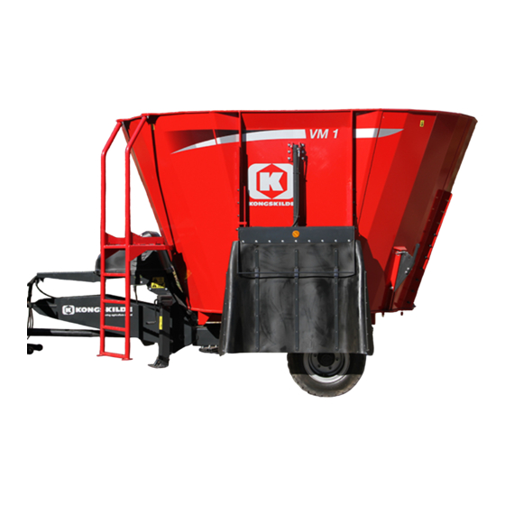
6 - WORKING OPERATIONS###_6_### General information Implement overview The KONGSKILDE VM Diet Mixer models allow to mix the chopped straw fodder quickly and efficiently with other types of feed. The mixer shreds all types of bale - round as well as square. -
Page 66: Clutch
(connection of the Power Take-Off (PTO)). NOTE: For VM-1 and VM-1 S the shear bolt is located on the first PTO (between tractor and implement). NOTE: For all the other models the shear bolt is located on the second PTO. - Page 67 6 - WORKING OPERATIONS The next figures illustrate how the friction clutch protects the transmission against high torque peaks and at the same time is capable of transmitting the torque while it is in function (slips). (a) Torque without clutch (b) Starting torque (c) Overload ZEIL18HT00371AA...
-
Page 68: Transmission Securing Against Overload
6 - WORKING OPERATIONS Transmission securing against overload NOTE: The tractor driver can secure the transmission against overload. When you use the implement, consider the following steps: 1. Always start the implement with the engine running at low speed. This especially applies to tractors with electro-hydraulic connection of the Power Take-Off (PTO) shaft. -
Page 69: Electro-Hydraulic (Eh) Controls
6 - WORKING OPERATIONS Electro-Hydraulic (EH) controls ZEIL21HT00190FA The electric operating systems can operate between two and nine hydraulic functions. This is solved hydraulically by having a corresponding number of section valves, which are bolted together with a bypass valve (V0). There are three different types of bypass valve: •... - Page 70 6 - WORKING OPERATIONS The hydraulic supporting leg is fitted with a ball valve for parking. There is also an integral double pilot-controlled non-return valve, which prevents the feeder from dropping in the event of a leak or hose rupture. •...
-
Page 71: Feed Dispensing
6 - WORKING OPERATIONS Feed dispensing DANGER IMPROPER OPERATION OF THIS MACHINE CAN CAUSE DEATH OR SERIOUS INJURY. Keep all persons, including their clothing, away from the auger when the auger is in motion. Failure to comply will result in death or seri- ous injury. - Page 72 6 - WORKING OPERATIONS Cross conveyor With the cross conveyor fitted to the feeder, it is possible to eject the feed away from the feeder, which prevents from driving over the feed, even when large quantities of feed are being dispensed. In order for the cross conveyor to function correctly, the hydraulic hoses from the tractor must be fitted correctly, so that the pressure and return connections are connected...
-
Page 73: Blades
6 - WORKING OPERATIONS Blades The compact auger also called the S auger is fitted in some types of feeders. It is fitted with five normal, hard- ened blades. However, the auger is prepared for a further seven blades. ZEIL21HT00128AA The normal auger is fitted in other types of feeders. - Page 74 6 - WORKING OPERATIONS Long blade The long blade (B) is not just longer, but also tungsten- coated (C), which is a major advantage in terms of wear. This blade is the right solution if large quantities of hay are used.
-
Page 75: Door Indicator Monitor Display (For Vm-2 And Vm-3 Models, If Equipped)
6 - WORKING OPERATIONS Door indicator monitor display (for VM-2 and VM-3 models, if equipped) Door indicator monitor display is a display for rear side doors and corner doors on two and three auger imple- ments. ZEIL22HT00010AA 6-11... -
Page 76: Working In The Field
6 - WORKING OPERATIONS Working in the field DANGER WARNING Pinch hazard! Rotating parts! Keep your hands, feet, and body clear of all Before you remove any guards, stop the trac- moving parts and oscillating points. tor and remove the key. Use lock-out tags or Failure to comply will result in death or seri- other procedures as required to prevent unan- ous injury. - Page 77 6 - WORKING OPERATIONS Filling of feed If adding whole bales, it is possible to start with these, as the feed volume will increase substantially once they have been shredded. The RPM can be increased and the shear bars used to accelerate the shredding.
- Page 78 6 - WORKING OPERATIONS Weighing The feeder is fitted with a wireless weighing system, which consists of a large main terminal, which is usually located in the loading tractor, and one or more small hand termi- nals, that are typically placed in the tractor in front of the feed trailer, or it can be carried in the case of manual re- filling.
- Page 79 6 - WORKING OPERATIONS Using the weighing system with the tractor uncoupled The feeder can be fitted with a battery to operate the weighing system, which enables the weighing system to be used without the feeder coupled to a tractor. To install the battery in the equipment compartment, proceed as follows: 1.
- Page 80 6 - WORKING OPERATIONS Operating the self steering shaft The feed trailer can be supplied with a selfsteering shaft, so that the two rearmost wheels, and on the VM-3 with triple axle, the two foremost wheels, can be rotated. This considerably extends the life of the tyres and protects the ground.
-
Page 81: Adjustments
6 - WORKING OPERATIONS Adjustments Brake settings Setting the brake arms The angle (V) must not exceed 90° relative to the horizon- tal when the brakes are activated. Adjustment can be carried out in one of two ways, depending on the brake arm design: 1. -
Page 82: Repairs Involving Welding
6 - WORKING OPERATIONS Repairs involving welding If any repairs involving welding is carried out, electric cur- rent must never pass through a weighing cell. This can be avoided by opening junction box (1) and removing the cables for weighing cells (2). NOTE: The welding apparatus’... -
Page 83: Replacement Of Blades
6 - WORKING OPERATIONS Replacement of blades CAUTION Cutting hazard! Use care handling sharp components. Always wear appropriate Personal Protective Equip- ment (PPE), including heavy gloves. Failure to comply could result in minor or moderate injury. C0139A The durability of the blades (1) will strongly depend on the feed products being used. -
Page 84: Conveyor Adjustments
6 - WORKING OPERATIONS Conveyor Adjustments The conveyor should be adjusted if it is not operating correctly or is pushing against one side or slipping on the rollers. All conveyors should generally be tension in length: • Standard conveyor: 1.0% •... -
Page 85: Elevator Belt Adjustment
6 - WORKING OPERATIONS Elevator belt adjustment To access the tensioning screws, remove the cover plate (1). The elevator toothed belt can be tightened by turning ten- sioning screws (2) anticlockwise after the nuts have been loosened. Tighten until the distance (L) across (N) ten teeth is about 504.0 mm (19.8 in) and then test to see whether the belt runs correctly. -
Page 86: Wear Plates (If Equipped)
6 - WORKING OPERATIONS Wear plates (if equipped) Both auger sizes can be fitted with the “Mix+” wear plate set (2) outermost on the windings. This considerably ex- tends the life of the auger. It is recommended that the wear plates be replaced before the outer edge has been worn down to the auger itself. -
Page 87: Conveyor Accessories (If Equipped)
6 - WORKING OPERATIONS Conveyor accessories (if equipped) Elevator The implement can be supplied with an elevator on the side, available in various lengths. It is recommended to use a manually operated valve block or electrically operated hydraulics. During transport, the elevator can be lifted all the way in to the mixing hopper. -
Page 88: Reduction Gear (If Equipped)
6 - WORKING OPERATIONS Reduction gear (if equipped) It is possible to have a reduction gear fitted as extra equip- ment. A reduction gear enables a smaller tractor to be used to drive the feed trailer. During the actual mixing process and at the start of feed dispensing, the reduction gear must be in the low gear (handle up). -
Page 89: Maintenance
7 - MAINTENANCE MAINTENANCE###_7_### General information General WARNING Improper operation or service of this machine can result in an accident. If you do not understand a maintenance proce- dure, or doubt your ability to perform a main- tenance procedure correctly, see your autho- rized dealer. - Page 90 Observe the recommended greasing, replacement and in- spection intervals to prevent secondary damages. Only use original KONGSKILDE spare parts to avoid un- intentional risks and damages. Install the used spare parts correctly and torque all the...
- Page 91 7 - MAINTENANCE Always replace worn or frayed belts before they fail. Always replace canvas on the header that are worn or torn. Tubes, hoses, electrical wiring, etcetera that are worn or damaged must be replaced immediately. Hydraulic system When you replace parts of the hydraulic system, always make sure that the header rests on the ground.
- Page 92 Use the indicated consumable to maintain the oil level in the gearboxes. Oil for the gearboxes is available from your KONGSKILDE dealer. NOTICE: Failure to use the correct specification of oil may lead to premature failure of the gearbox components.
-
Page 93: Torque
7 - MAINTENANCE Torque Minimum hardware tightening torques (in N m or lb in /lb ft) for normal assembly applica- tions unless otherwise stated The minimum hardware tightening torque on drawings, in specifications, etcetera have priority. In the following tables, torque specifications are shown following the standard ENS7001, applicable for material class 8.8 and material class 10.9. - Page 94 7 - MAINTENANCE Identification markings Metric hex head, flange hex head and carriage bolts, Classes (CL) 5.6 and upward NHIL14RB00662AA Metric bolt identification markings 1. Manufacturer's identification 2. Property class...
- Page 95 7 - MAINTENANCE Metric hex nuts and locknuts, Classes (CL) 05 and upward NHIL14RB00663AA Metric hex nut identification markings • (1) – Manufacturer's identification • (3) – Property class • (2) – Clockwise type markings indicate property class and may include manufacturer identification (if applied), Example: property marks 240°...
-
Page 96: Grease Fittings And Intervals
7 - MAINTENANCE Grease fittings and intervals Regular lubrication is the best insurance against delays and repairs. Proper lubrication will extend the life of the implement. Grease fittings On new implements, the grease fitting may be covered with paint. Remove the paint to ensure the grease fitting can accept grease. - Page 97 7 - MAINTENANCE Progressive lubrication block The implement may be equipped with a progressive lubri- cation block. This block ensures that the grease points connected re- ceive the correct quantity of grease. All guards have been fitted with locks for safety reasons. Lubrication must be performed individually at the interval specified if the implement has not been fitted with a lubri- cation block.
-
Page 98: Pressure Washing
7 - MAINTENANCE Pressure washing WARNING Flying debris! Always wear protective clothing and safety glasses or a face shield when using a steam cleaner or power washer. Failure to comply could result in death or se- rious injury. W0314A NOTE: Legislation in certain countries and good practice requires special treatment of waste water through sed- imentation and oil separation and controlled removal of residues. -
Page 99: Fluids, Lubricants, And Capacities
ASTROL LPHASYN Planet gearbox 10.8 – 14.0 L (2.9 – GEAR SYN PAO 150 DIN 51517-3 - ETRONAS VM-1 S 3.7 US gal) ™ EP 150 ASTROL LPHASYN Two planet 10.8 – 23.0 L (2.9 – GEAR SYN PAO 150... -
Page 100: Maintenance Planning
After the first 10 hours Wheels and tires - check 7-13 After the first 100 hours Reduction gear oil change 7-13 Planet gear oil change (for VM-1 models) 7-14 7-15 Planet gear oil change (for VM-2 and VM-3 models) Daily Check bolted connections... -
Page 101: After The First 10 Hours
7 - MAINTENANCE After the first 10 hours Wheels and tires - check NOTICE: Check the wheels and tires after the first 10 h of operation. Make sure to torque the wheel hardware any time that you remove and install a wheel. NOTICE: Do not substitute a tire of a different size. -
Page 102: Planet Gear Oil Change (For Vm-1 Models)
7 - MAINTENANCE Planet gear oil change (for VM-1 models) Planet gearbox VM-1 To change the gearbox oil, proceed as follows: 1. Place the implement on a level surface. 2. Remove the uppermost hose and the vent plug on the equalisation vessel. -
Page 103: Planet Gear Oil Change (For Vm-2 And Vm-3 Models)
7 - MAINTENANCE Planet gear oil change (for VM-2 and VM-3 models) Two planet gears To change the gearbox oil, proceed as follows: 1. Place the implement on a level surface. 2. Remove the uppermost hose and the vent plug on the equalisation vessel. -
Page 104: Daily
7 - MAINTENANCE Daily Check bolted connections Torque again all the bolts, the nuts and the fasteners daily. Rotating parts - check During the season check daily that no blades, carriers, fingers of the conditioners or bolts are missing. If any of these parts are missing, install the missing parts before you continue the work. -
Page 105: Every 10 Hours
7 - MAINTENANCE Every 10 hours 10 hours grease fittings Power Take-Off (PTO) shaft 1. Cross bearings in PTO shaft (x2) ZEIL22HT00002AA 2. Profile tube in foremost PTO shaft ZEIL22HT00002AA Wide angle shaft 3. Cross bearings in wide angle shaft (x3) ZEIL22HT00001AA 7-17... - Page 106 7 - MAINTENANCE 4. Double fork in wide angle shaft ZEIL22HT00001AA 7-18...
-
Page 107: Every 40 Hours
7 - MAINTENANCE Every 40 hours 40 hours grease fittings Drawbar 1. Hitch eye (1 x feeder) ZEIL22HT00008AA 2. Supporting base (1 x feeder) ZEIL22HT00008AA 3. Input shaft (1 x feeder) ZEIL22HT00008AA 7-19... - Page 108 7 - MAINTENANCE Doors 4. Guides for door (x4) ZEIL21HT00146AA Input shaft 5. Input shaft fitted to feeders without reduction gear (2 x feeder) ZEIL21HT00156AA Discharge conveyor 6. Bearing housing adjacent to oil motor (2 x feeder) ZEIL21HT00155AA 7-20...
- Page 109 7 - MAINTENANCE Power Take-Off (PTO) shaft 7. Guard (x2) ZEIL22HT00002AA 7-21...
-
Page 110: Every 3 Months
7 - MAINTENANCE Every 3 months 3 months grease fittings (for VM-2 models) Boogie 1. Pivot joint for self-steering (x4) ZEIL21HT00148AA 2. Bearings for brake arm (2 x brake arm) ZEIL21HT00148AA 3. Swivel bearing for bogie springs (x2) ZEIL21HT00148AA 7-22... - Page 111 7 - MAINTENANCE 4. Tap for tandem or triple (x12) ZEIL21HT00147AA 7-23...
-
Page 112: Months Grease Fittings (For Vm-3 Models)
7 - MAINTENANCE 3 months grease fittings (for VM-3 models) Tandem 1. Tap for tandem or triple (x12) ZEIL21HT00147AA 7-24... -
Page 113: Wheels And Tires - Check
7 - MAINTENANCE Wheels and tires - check Check the wheels and tires every 50 h of operation. Perform a follow-up check of the wheel hardware torque after every 50 h of operation. Make sure to torque the wheel hardware any time that you remove and install a wheel. -
Page 114: Every 250 Hours
7 - MAINTENANCE Every 250 hours Hydraulic hoses Periodically check the hydraulic hoses for leaks, dam- age, and maintain a hydraulic hose service-life aware- ness. Check for the following: • The dates on the crimped hose end fittings. See Page 7-32. •... -
Page 115: 250 Hours Grease Fittings
7 - MAINTENANCE 250 hours grease fittings 1. Shear bolt clutch ZEIL22HT00060AA 7-27... -
Page 116: Every 2000 Hours Or Every Year
7 - MAINTENANCE Every 2000 hours or every year 2000 hours grease fittings Wheels 1. Wheel hub (x4) ZEIL21HT00148AA Weighing cells 2. Ball joint for weighing cells (1 x cell) ZEIL22HT00008AA 7-28... -
Page 117: Reduction Gear Oil Change
7 - MAINTENANCE Reduction gear oil change Reduction gear To change the gearbox oil, proceed as follows: 1. Place the implement on a level surface. 2. Place a suitable container below the drain plug (3) of the reduction gearbox. 3. Remove the drain plug (3) and drain all the oil from the reduction gearbox. -
Page 118: Planet Gear Oil Change (For Vm-1 Models)
7 - MAINTENANCE Planet gear oil change (for VM-1 models) Planet gearbox VM-1 To change the gearbox oil, proceed as follows: 1. Place the implement on a level surface. 2. Remove the uppermost hose and the vent plug on the equalisation vessel. -
Page 119: Planet Gear Oil Change (For Vm-2 And Vm-3 Models)
7 - MAINTENANCE Planet gear oil change (for VM-2 and VM-3 models) Two planet gears To change the gearbox oil, proceed as follows: 1. Place the implement on a level surface. 2. Remove the uppermost hose and the vent plug on the equalisation vessel. -
Page 120: Every Six Years
7 - MAINTENANCE Every six years Hydraulic hoses WARNING Escaping fluid! Do not disconnect hydraulic quick coupler under pressurized conditions. Make sure all hydraulic pressure is removed from the system before disconnecting hydraulic quick coupler. Failure to comply could result in death or serious injury. W0095A WARNING Escaping fluid! -
Page 121: As Required
7 - MAINTENANCE As required Wheel hub lubrication – Grease To lubricate the wheel hubs, proceed as follows: 1. Disassemble the wheel hubs. 2. Clean the hubs thoroughly inside and out. 3. Clean and inspect both of the wheel bearings. 4. -
Page 122: Friction Slip Clutch - Burnish (Resurface)
7 - MAINTENANCE Friction slip clutch – Burnish (resurface) WARNING Moving parts! Disengage the Power Take-Off (PTO), turn off the engine, and remove the key. Wait for all movement to stop before you leave the operator's position. Never adjust, lubricate, clean, or remove a blockage of crop material when the engine is on. -
Page 123: Shear Bolt Clutch
7 - MAINTENANCE Shear bolt clutch In case of overloading, the shear bolt breaks and the power transmission is interrupted. In this case proceed as follows: 1. Replace the shear bolt (1) with a bolt of the same di- mensions and strength class. NOTE: Pay attention to the thread length. -
Page 124: Magnet On Cover Plate
7 - MAINTENANCE Magnet on cover plate WARNING Magnetic field! Magnets could affect the functioning of pacemakers and implanted heart defibrillators. If you wear these devices, then keep sufficient distance from the magnets. Warn others who wear these devices to not get too close to magnets. Failure to comply could result in death or serious injury. -
Page 125: Check The Wheel Bearing
7 - MAINTENANCE Check the wheel bearing To adjust the play in the wheel bearing, proceed as fol- lows: 1. Raise the axle off the ground until the wheel spins freely. 2. Take off the hub cap, remove the cotter pin and tighten the hub nut until there is noticeable resistance. -
Page 126: End Of Season Service
7 - MAINTENANCE Storage End of season service When the season is over, prepare the implement for the storage immediately. To prepare the implement for winter storage: 1. Clean the implement thoroughly. Dust and dirt absorb moisture and moisture increases the formation of rust. 2. -
Page 127: Implement Long-Term Storage And/Or Disposal
Implement long-term storage and/or disposal When the implement reaches the end of its useful life, observe the following recommendations for disposal: • See your KONGSKILDE dealer to make an agree- ment for your dealer to properly dispose of the im- plement, or •... - Page 128 (such as com- pressed springs in belt variators). If you do not have the proper tools or instructions to disassemble a sys- tem or component, contact your KONGSKILDE dealer to perform this service. NOTE: Make sure that the implement maintains stability during the dismantling process.
-
Page 129: Ordering Parts And/Or Accessories And / Or Accessories
Order and install the spare parts and/or accessories at once before the next season. When you order spare parts, always make sure to give your KONGSKILDE dealer the model number and the Product Identification Number (PIN) of your implement. See “Product identification” in Chapter 1 of this opera- tor’s manual. - Page 130 7 - MAINTENANCE 7-42...
-
Page 131: Troubleshooting
Fault code resolution General This chapter describes the easy diagnostic methods for generic problems and the related remedies for them. If you cannot find the cause of a problem or solve a problem, consult the KONGSKILDE dealer. Troubleshooting Problem Possible Cause Correction... - Page 132 8 - TROUBLESHOOTING...
-
Page 133: Specifications
9 - SPECIFICATIONS SPECIFICATIONS###_9_### Dimensions (for VM-1 models) VM-1 S and VM-1 ZEIL21HT00175HA... - Page 134 9 - SPECIFICATIONS Description Dimension VM 6.5-1 S VM 8-1 S VM 10-1 S VM 10- 1 VM 12- 1 VM 14- 1 4.34 m 4.4 m 4.4 m 4.66 m 4.66 m 4.66 m Total length, standard (170.9 in) (173.2 in) (173.2 in) (183.5 in)
- Page 135 9 - SPECIFICATIONS VM-1 B and VM-1 B X ZEIL21HT00176HA...
- Page 136 9 - SPECIFICATIONS VM 10- 1 B VM 12- 1 B VM 14- 1 B Dimension Description VM 10 -1 B VM 12 -1 B VM 14 -1 B 5.43 m 5.43 m 5.43 m 5.43 m 5.43 m 5.43 m Length, Models B and B X (213.8 in) (213.8 in)
- Page 137 9 - SPECIFICATIONS VM-1 B M ZEIL21HT00177HA...
- Page 138 9 - SPECIFICATIONS Description Dimension VM 10 -1 B M VM 12 -1 B M VM 14 -1 B M Length 6.05 m (238.2 in) 6.05 m (238.2 in) 6.05 m (238.2 in) Length 4.66 m (183.5 in) 4.66 m (183.5 in) 4.66 m (183.5 in) –...
-
Page 139: Dimensions (For Vm-2 Models)
9 - SPECIFICATIONS Dimensions (for VM-2 models) VM-2 S and VM-2 ZEIL21HT00178HA... - Page 140 9 - SPECIFICATIONS Dimen- VM 12-2 VM 14-2 VM 16-2 VM 18-2 VM 20-2 Description VM 20- 2 VM 22- 2 VM 27- 2 VM 30- 2 sion 6.25 m 6.31 m 6.31 m (2 6.31 m 6.5 m 7.2 m 7.2 m 7.2 m 7.31 m...
- Page 141 9 - SPECIFICATIONS Dimen- VM 12-2 VM 14-2 VM 16-2 VM 18-2 VM 20-2 Description VM 20- 2 VM 22- 2 VM 27- 2 VM 30- 2 sion 0.77 – 0.77 – 0.77 – 0.77 – 0.86 – 0.74 – 0.79 –...
- Page 142 9 - SPECIFICATIONS VM-2 SB and VM-2 SB X ZEIL21HT00181HA 9-10...
- Page 143 9 - SPECIFICATIONS VM 14 -2 VM 16 -2 VM 18 -2 VM 20 -2 VM 14- 2 VM 16- 2 VM 18- 2 VM 20- 2 Dimension Description SB X SB X SB X SB X 6.98 m (2 6.98 m (2 6.98 m (2 7.18 m (2...
- Page 144 9 - SPECIFICATIONS VM-2 SB M ZEIL21HT00180HA 9-12...
- Page 145 9 - SPECIFICATIONS Description Dimension VM 14 -2 SB M VM 16 -2 SB M VM 18 -2 SB M VM 20 -2 SB M Length 7.6 m (299.2 in) 7.6 m (299.2 in) 7.6 m (299.2 in) 7.8 m (307.1 in) Length 5.38 m (211.8 in) 5.38 m (211.8 in)
- Page 146 9 - SPECIFICATIONS VM-2 B and VM-2 B X ZEIL21HT00181HA 9-14...
- Page 147 9 - SPECIFICATIONS Dimension Description 20-2B 22-2B 27-2B 30-2B 20-2B X 22-2B X 27-2B X 30-2B X 7.88 m (3 7.88 m (3 7.88 m (3 7.88 m (3 7.88 m (3 7.88 m (3 7.88 m (3 7.88 m (3 Length, Models B and B X 10.2 in) 10.2 in)
-
Page 148: Dimensions (For Vm-3 Models)
9 - SPECIFICATIONS Dimensions (for VM-3 models) VM-3 S and VM-3 ZEIL21HT00183HA 9-16... - Page 149 9 - SPECIFICATIONS VM 21-3 VM 24-3 VM 26-3 VM 28-3 Dimension Description VM 29- 3 VM 32- 3 VM 38- 3 VM 45- 3 8.61 m (3 8.61 m (3 8.61 m ( 8.83 m (3 9.34 m (3 9.34 m ( 9.34 m (3 9.45 m (3...
- Page 150 9 - SPECIFICATIONS VM-3 SB and VM-3 SB X ZEIL21HT00184HA 9-18...
- Page 151 9 - SPECIFICATIONS VM 21 -3 VM 24 -3 VM 26 -3 VM 28 -3 VM 21 -3 VM 24- 3 VM 26- 3 VM 28- 3 Dimension Description SB X SB X SB X SB X 9.09 m (3 9.09 m (3 9.09 m (3 9.29 m (3...
- Page 152 9 - SPECIFICATIONS VM-3 B and VM-3 B X ZEIL21HT00186HA 9-20...
- Page 153 9 - SPECIFICATIONS Dimension Description 29-3B 32-3B 38-3B 45-3B 29-3B X 32-3B X 38-3B X 45-3B X 9.96 m (3 9.96 m (3 9.96 m (3 10.15 m ( 9.96 m (3 9.96 m (3 9.96 m (3 10.15 m ( Length, Models B and B X 92.1 in) 92.1 in)
-
Page 154: Technical Data (For Vm-1 Models)
9 - SPECIFICATIONS Technical data (for VM-1 models) VM-1 S Type VM 6.5-1 S (1 SL) VM 8-1 S (1 SL) VM 10-1 S (1 SL) Volume 6.5 m³ (229.5 ft³) 8 m³ (282.5 ft³) 10 m³ (353.1 ft³) Power output requirement... - Page 155 9 - SPECIFICATIONS VM-1 / VM-1 B / VM-1 B X / VM-1 B M Type VM 10-1 VM 12-1 VM 14-1 VM 10-1 B VM 12-1 B VM 14-1 B VM 10-1 B X VM 12-1 B X VM 14-1 B X...
-
Page 156: Technical Data (For Vm-2 Models)
9 - SPECIFICATIONS Technical data (for VM-2 models) VM-2S / VM-2 SB / VM-2 SB X / VM-2 SB M Type VM 12-2 S VM 14-2 S VM 16-2 S VM 18-2 S VM 20-2 S VM 14-2 SB VM 16-2 SB VM 18-2 SB VM 20-2 SB VM 14-2 SBX... - Page 157 9 - SPECIFICATIONS VM-2 / VM-2 B / VM-2 B X Type VM 20-2 VM 22-2 VM 27-2 VM 30-2 VM 20-2 B VM 22-2 B VM 27-2 B VM 30-2 B VM 20-2 BX VM 22-2 BX VM 27-2 BX VM 30-2 BX Volume 20 m³...
-
Page 158: Technical Data (For Vm-3 Models)
9 - SPECIFICATIONS Technical data (for VM-3 models) VM-3 S / VM-3 SB / VM-3 SB X Type VM 21-3 S VM 24-3 S VM 26-3 S VM 28-3 S VM 21-3 SB VM 24-3 SB VM 26-3 SB VM 28-3 SB VM 21-3 SBX VM 24-3 SBX VM 26-3 SBX... - Page 159 9 - SPECIFICATIONS VM-3 / VM-3 B / VM-3 B X Type VM 29-3 VM 32-3 VM 38-3 VM 45-3 VM 29-3 B VM 32-3 B VM 38-3 B VM 45-3 B VM 29-3 BX VM 32-3 BX VM 38-3 BX VM 45-3 BX Volume 29 m³...
-
Page 160: Fluids, Lubricants, And Capacities
ASTROL LPHASYN Planet gearbox 10.8 – 14.0 L (2.9 – GEAR SYN PAO 150 DIN 51517-3 - ETRONAS VM-1 S 3.7 US gal) ™ EP 150 ASTROL LPHASYN Two planet 10.8 – 23.0 L (2.9 – GEAR SYN PAO 150... -
Page 161: Hydraulic Diagram Fct 1060
9 - SPECIFICATIONS Hydraulic diagram FCT 1060 The following scheme of the hydraulic diagram is present as a representative and is applicable for the FCT 1060. ZEIL21HT00189FA Item Description Pressure hose Return hose (T1) Prop plug (A1) Input for hydraulic function (A2) Input for hydraulic function (A3) -
Page 162: Tires
9 - SPECIFICATIONS Tires The implement is as standard equipped with wide tires which provide extra large carrying capacity and thus a low ground pressure. The following table specifies the recommended tire pres- sure ranges for the various tire sizes. Tire dimension Recommended tire pressure... -
Page 163: 10 - Accessories
10 - ACCESSORIES 10 - ACCESSORIES###_10_### General information Accessories or optional equipment listed hereafter may be part of the standard equipment for certain countries. Some of these accessories or options may not be avail- able in certain markets. Wear plates Both auger sizes can be fitted with the “Mix+”... -
Page 164: Conveyor Accessories
10 - ACCESSORIES Conveyor accessories Elevator The implement can be supplied with an elevator on the side, available in various lengths. It is recommended to use a manually operated valve block or electrically operated hydraulics. If it is needed to post-mix feed or discharge feed into a feed truck or similar, the implement can be supplied with an elevator on either the side or the back. -
Page 165: Hydraulic Gear Change
10 - ACCESSORIES Hydraulic gear change As extra equipment, it is possible for trailers with a reduc- tion gear to be fitted with the hydraulic gear change (Hy- drostep). The hydraulic gear change makes it possible to change gear without leaving the tractor driver cab. ZEIL21HT00142AA Auger extension Auger extension extends the standard auger with 35.0 cm... -
Page 166: Slow-Moving Vehicle (Smv) Sign
10 - ACCESSORIES Slow-Moving Vehicle (SMV) sign WARNING Collision hazard! Collision of high speed road traffic and slow moving machines can cause death or per- sonal injury. On roads use transport lighting according to local laws. Make sure the Slow Moving Vehicle (SMV) emblem is visible. -
Page 167: 11 - Forms And Declarations
11 - FORMS AND DECLARATIONS 11 - FORMS AND DECLARATIONS###_11_### European Community (EC) Declaration of Conformity ACCORDING TO DIRECTIVES 2006/42/EC & 2014/30/EU Inside the European Community and for some specific countries, an EC Declaration of Conformity is separately de- livered with your implement. The EC Declaration of Conformity is the manufacturer's declaration about equipment compliance to relevant European Union (EU) provisions. - Page 168 11 - FORMS AND DECLARATIONS ZEIL22TIL0019FA 11-2...
- Page 169 For your better and easier understanding of the document, you will find the text reproduced hereafter. EC/EU Declaration of Conformity According to Directives 2006/42/EC & 2014/30/EU declare under our sole responsibility, that the product: Agricultural machine Commercial Name KONGSKILDE and Model: ... Denomination: Mixer Type (Specify any variant/version): ... Planning key: ... Serial Number: ...
- Page 170 11 - FORMS AND DECLARATIONS NOTE: Only for United Kingdom. ZEIL22TIL0020FA 11-4...
- Page 171 Conveyor Adjustments ........6-20 Dimensions (for VM-1 models) ........
- Page 172 Pressure washing......... 7-10 Product identification (for VM-1 models) ....... 1-10 Product identification (for VM-2 models) .
- Page 173 Technical data (for VM-1 models) ........9-22...
- Page 174 Availability of some models and equipment builds varies according to the country in which the equipment is being used. For exact information about any particular product, please consult your KONGSKILDE dealer. © 2022 CNH Industrial Belgium N.V. All rights reserved.
Need help?
Do you have a question about the VM-1 and is the answer not in the manual?
Questions and answers