Table of Contents
Advertisement
Quick Links
Advertisement
Table of Contents

Summary of Contents for AUSTRALIAN MONITOR ES Series
- Page 1 INSTALLATION AND OPERATION MANUAL ES SERIES MIXER AMPLIFIERS ES60 ES120 ES250...
-
Page 2: Important Safety Information
Assurez-vous que l’appareil est hors tension avant de connecter les hauts parleurs. Veri ez que la sortie des enceintes soit protégées contre un contact physique. Respecter les polarités des terminaux ainsi que le câblage des enceintes pendant le fonctionnement afin d’assurer une utilisation sécurisee. ES SERIES INSTALLATION AND OPERATION MANUAL... - Page 3 Congratulations on choosing Australian Monitor for your professional amplification requirements. Introduction Available in 60, 120 and 250 watt versions, the ES series are 1 or 2 Features & Protection Features RU mixer amplifiers, featuring 100 volt line and 4 ohm outputs, 4 universal mic/line inputs and record and line outputs.
-
Page 4: Protection Features
Integrated 5 Tone Generator with volume control (ES120 and ES250) ° Evac ° Alert ° Intruder ° Bell ° Chime • Rack mount size ° 1 RU for ES60 ° 2 RU for ES120/250 ES AMPLIFIER BLOCK DIAGRAM ES SERIES INSTALLATION AND OPERATION MANUAL... -
Page 5: Front Panel
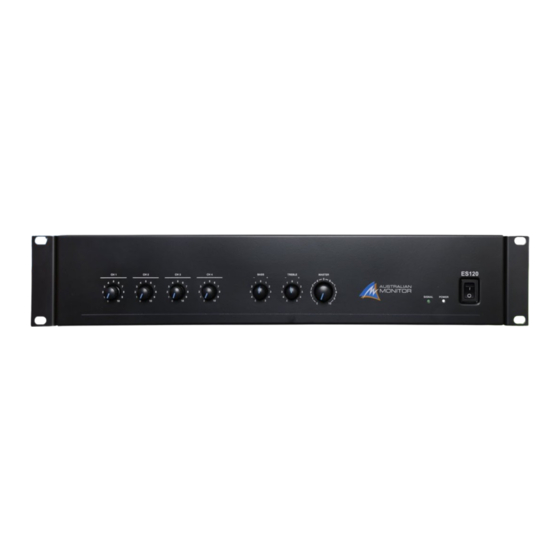
This LED indicates the unit is outputting a signal. POWER This LED indicates the unit is on. POWER SWITCH This switches the power to the unit on and off. The up position is on. ES SERIES INSTALLATION AND OPERATION MANUAL... -
Page 6: Rear Panel
Always replace the fuse with one of the same value and type. Always disconnect power to the amplifier before replacing fuses. PHANTOM POWER 12V phantom power is available for condenser or electret microphones on the XLR input when this switch is pushed down. ES SERIES INSTALLATION AND OPERATION MANUAL... -
Page 7: Priority Mode
This 6 pin terminal allows tones to be internally triggered for playback. Simply connect any of the tone inputs to the ground terminal (GND). Adjust the volume control to increase or decrease the tone level. See the tone generator section of the manual for further information. ES SERIES INSTALLATION AND OPERATION MANUAL... -
Page 8: Tone Volume
2. ‘ALERT’: a short tone burst tone repeated every 0.5s. Triggered by shorting ALERT to GND, the sound will continue to repeat until the short is released. 3. ‘INTRUDER’: a two tone ‘low’ ‘high’ alert repeating every 0.4s. Triggered by shorting INTRUDER to GND, the sound will continue to repeat until the short is released. ES SERIES INSTALLATION AND OPERATION MANUAL... -
Page 9: Installation
MOUNTING The ES Series amplifiers are one or two rack units high (1U) (2U) and will fit a standard EIA 19” or rack. Typically amplifiers may be stacked directly on top of each other with no need for spacing between units, unless installed in high ambient temperature environments where a single rack unit space between amplifiers will assist cooling further. -
Page 10: Input Connections
Balanced input wiring (shielded pair cable) is recommended. Unbalanced RCA wiring should be keep as short as possible. Female XLR Pin1 Gnd Pin3 Cold - Pin2 Hot + Male XLR Pin2 Hot + Pin3 Cold - Pin1 Gnd Tip: Hot + Shield: Gnd ES SERIES INSTALLATION AND OPERATION MANUAL... -
Page 11: Troubleshooting
1 and 2 Disable priority function using DIP switches on the rear panel. Tones do not sound when triggered Tone generator volume too low Increase the volume by turning the tone volume clockwise ES SERIES INSTALLATION AND OPERATION MANUAL... - Page 12 DIMENSIONS: ES60 ES SERIES INSTALLATION AND OPERATION MANUAL...
- Page 13 DIMENSIONS: ES120/ ES250 ES250 ES120 ES SERIES INSTALLATION AND OPERATION MANUAL...
-
Page 14: Specifications
12VDC @ 15mA per input pin INPUT/OUTPUTS MIC - Balanced XLR per channel AUDIO INPUT LINE - Unbalanced stereo RCA per channel RECORD OUTPUT Unbalanced Stereo RCA LINE OUTPUT Balanced XLR 6 pin Screw Terminal per channel SPEAKER OUTPUT ES SERIES INSTALLATION AND OPERATION MANUAL... -
Page 15: Power Requirements
IEC Mains cable, Rubber Feet x 4, 1 label sticker sheet ACCESSORIES One 1 x 6 terminal socket for ES120/ ES 250 APPROVALS CE, IEC, RCM Due to continuous improvements, all specifications are subject to change ES SERIES INSTALLATION AND OPERATION MANUAL... - Page 16 ENGINEERED BY AUSTRALIAN MONITOR Address: 1 Clyde St, Silverwater NSW 2128 Australia. Website: www.australianmonitor.com.au International enquiries email: international@australianmonitor.com.au ABN 35 007 573 417...


Need help?
Do you have a question about the ES Series and is the answer not in the manual?
Questions and answers