Table of Contents
Advertisement
Quick Links
Advertisement
Table of Contents

Related Manuals for AUSTRALIAN MONITOR ACM120XL


Summary of Contents for AUSTRALIAN MONITOR ACM120XL
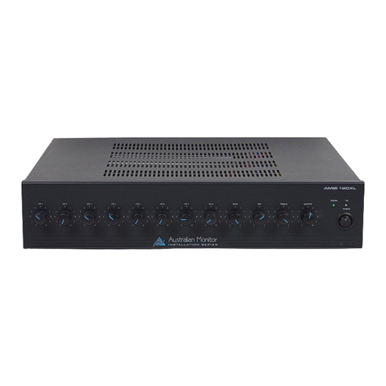
- Page 1 ACM120XL 120w Mixer Amplifier Operating Manual...
-
Page 2: Front Panel Features
Middle Control The Mid control is part of a 3 band equalization system within the ACM120XL. The Mid control allows the user to increase or decrease the amount of mids in the system. The control allows for 10dB of cut or boost at 600Hz. Depending on the speakers and application, a small cut (decrease) in the mids normally makes the system sound ‘warmer’. -
Page 3: Rack Mounting
When the amplifier is connected to an appropriate AC power source and is switched on, the blue LED will illuminate. Signal LED The green “Signal” LED located next to the On LED indicates that the ACM120XL is passing audio. The signal LED is a simple method to trouble-shoot installations especially in multi-amplifier projects. Rack Mounting The ACM120XL is supplied with rack ears attached to allow mounting within a standard 19”... -
Page 4: Tape Output
VCA Control An external pot (500 ohm to 1K) can be connected to the ACM120XL for remote control of the master level. While a 1K pot can used, better results (smoother volume adjustment) can be obtained by using a 500 ohm pot. The external pot is governed by the master level of the amplifier allowing the installer to set the volume, then lock the amplifier in a rack leaving the user with just a master volume control that cannot go beyond the level set on the master (front panel) control. -
Page 5: Microphone Inputs
(than the 120 watts of the ACM120XL) is required. In this situation, a standard microphone lead is used to connect the line output of the ACM120XL to the line input of a power amplifier. The speaker load then needs to be split into two (one for each amplifier) making sure that each amplifier is driving no more than it’s recommended load. - Page 6 To disable muting from input 3, simply move jumper JP3 towards the back of the chassis. Another feature of the muting circuit of the ACM120XL is the ability to have inputs 1 and 2 on the same priority level. This is handy for situations where phone paging and microphone paging (for example) are of equal importance. In this mode, both inputs can be used at the same time and both will mute all remaining channels.
- Page 7 Important Safety Information 13. Do not block fan intake or exhaust ports. Do not 1. Save the carton and packing material even if the equip- operate equipment on a surface or in an environment ment has arrived in good condition. Should you ever which may impede the normal flow of air around the need to ship the unit, use only the original factory pack- ing.
- Page 8 Engineered by Audio Telex Communications Pty Ltd, Sydney, Australia A.B.N. 78 001 345 482 Inc in NSW www.audiotelex.com.au Export Sales & Corporate Head Office Private Bag 149, Silverwater NSW 1811 149 Beaconsfield Street, Silverwater NSW 2128 Australia Ph: 61-2- 9647 1411 Fax: 61-2-9748 2537 E-mail: ho@audiotelex.com.au Sydney (NSW &...
Need help?
Do you have a question about the ACM120XL and is the answer not in the manual?
Questions and answers