Table of Contents
Advertisement
Quick Links
Download this manual
See also:
User Manual
Advertisement
Table of Contents

Subscribe to Our Youtube Channel
Related Manuals for HT IRONMETER


Summary of Contents for HT IRONMETER
- Page 1 Copyright HT ITALIA 2015 Release 1.00 - 18/12/2015...
- Page 2 ENGLISH User manual Copyright HT ITALIA 2015 Version EN 1.00 - 18/12/2015...
-
Page 3: Table Of Contents
IRONMETER Table of contents: PRECAUTIONS AND SAFETY MEASURES ............... 2 1.1. Preliminary instructions ..................... 2 1.2. During use ......................... 3 1.3. After use ..........................3 1.4. Definition of Measurement (Overvoltage) category ............3 GENERAL DESCRIPTION ................... 4 ... -
Page 4: Precautions And Safety Measures
IRONMETER 1. PRECAUTIONS AND SAFETY MEASURES The instrument has been designed in compliance with directive IEC/EN61010-1 relevant to electronic measuring instruments. For your safety and in order to prevent damaging the instrument, please carefully follow the procedures described in this manual and read all notes preceded by symbol with the utmost attention. -
Page 5: During Use
IRONMETER 1.2. DURING USE Please carefully read the following recommendations and instructions: CAUTION Failure to comply with the caution notes and/or instructions may damage the instrument and/or its components or be a source of danger for the operator. Before activating the rotary switch, disconnect the test leads from the circuit being measured. -
Page 6: General Description
IRONMETER 2. GENERAL DESCRIPTION The instrument carries out the following measurements: DC voltage AC TRMS voltage DC current AC TRMS current Resistance and Continuity test Frequency Duty Cycle Diode test Capacity Each of these functions can be activated by means of the appropriate switch. -
Page 7: Operating Instructions
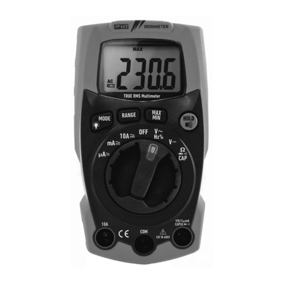
IRONMETER 4. OPERATING INSTRUCTIONS 4.1. DESCRIPTION OF THE INSTRUMENT 4.1.1. Description of the controls CAPTION: 1. LCD display 2. RANGE key 3. MAXMIN key 4. MODE/ key 5. HOLD/ key 6. Rotary selector switch 7. Input terminal 10A 8. Input terminal VHz%mACAP... -
Page 8: Description Of Function Keys
IRONMETER 4.2. DESCRIPTION OF FUNCTION KEYS 4.2.1. HOLD/ Pressing the HOLD/ key freezes the value of the measured quantity on the display. After pressing this key, the message appears on the display. Press the HOLD/ key again “ ” to exit the function. -
Page 9: Description Of Rotary Switch Functions
IRONMETER 4.3. DESCRIPTION OF ROTARY SWITCH FUNCTIONS 4.3.1. DC Voltage measurement CAUTION The maximum input DC voltage is 600V. Do not measure voltages exceeding the limits given in this manual. Exceeding voltage limits could result in electrical shocks to the user and damage to the instrument. -
Page 10: Ac Voltage Measurement
IRONMETER 4.3.2. AC Voltage measurement CAUTION The maximum input AC voltage is 600V. Do not measure voltages exceeding the limits given in this manual. Exceeding voltage limits could result in electrical shocks to the user and damage to the instrument. -
Page 11: Resistance Measurement And Continuity Test
IRONMETER 4.3.3. Resistance measurement and Continuity test CAUTION Before attempting any resistance measurement, cut off power supply from the circuit to be measured and make sure that all capacitors are discharged, if present. Fig. 5: Use of the instrument for resistance measurement and continuity test 1. -
Page 12: Diode Test
IRONMETER 4.3.4. Diode test CAUTION Before attempting any resistance measurement, cut off power supply from the circuit to be measured and make sure that all capacitors are discharged, if present. Fig. 6: Use of the instrument for diode test 1. Select position ... -
Page 13: Capacitance Measurement
IRONMETER 4.3.5. Capacitance measurement CAUTION Before carrying out capacitance measurements on circuits or capacitors, cut off power supply from the circuit being tested and let all capacitance in it be discharged. When connecting the multimeter and the capacitance to be measured, respect the correct polarity (when required). -
Page 14: Dc Current Measurement
IRONMETER 4.3.6. DC Current measurement CAUTION Maximum input DC current is 10A (input 10A) or 400mA (input VHz%mACAP ). Do not measure currents exceeding the limits given in this manual. Exceeding voltage limits could result in electrical shocks to the user and damage to the instrument. -
Page 15: Ac Current Measurement
IRONMETER 4.3.7. AC Current measurement CAUTION Maximum input AC current is 10A (input 10A) or 400mA (input VHz%mAACAP ). Do not measure currents exceeding the limits given in this manual. Exceeding voltage limits could result in electrical shocks to the user and damage to the instrument. -
Page 16: Maintenance
IRONMETER 5. MAINTENANCE CAUTION Only expert and trained technicians should perform maintenance operations. Before carrying out maintenance operations, disconnect all cables from the input terminals. Do not use the instrument in environments with high humidity levels or high temperatures. Do not expose to direct sunlight. -
Page 17: Technical Specifications
IRONMETER 6. TECHNICAL SPECIFICATIONS 6.1. TECHNICAL CHARACTERISTICS Accuracy calculated as [%reading + (num. digits*resolution)] at 18°C 28°C <75%HR DC Voltage Protection against Range Resolution Accuracy Input impedance overcharge 400.0mV 0.1mV 4.000V 0.001V (1.0%rdg + 3digits) 40.00V 0.01V 600VDC/ACrms >10M... - Page 18 IRONMETER Resistance and Continuity test Protection against Range Resolution Accuracy Buzzer overcharge 400.0 0.1 4.000k 0.001k (1.5%rdg + 5digits) 40.00k 0.01k <50 600VDC/ACrms 400.0k 0.1k 4.000M 0.001M (2.5%rdg + 20digits) 40.00M 0.01M Frequency (electronic circuits) Range Resolution Accuracy Sensitivity: 10.00Hz 10kHz (1.2%rdg)
-
Page 19: Reference Standards
IRONMETER 6.1.1. Reference standards Safety: IEC/EN61010-1 EMC: IEC/EN61326-1 Insulation: double insulation Pollution level: Measurement category: CAT III 600V Max operating altitude: 2000m (6562ft) Drop test: 6.1.2. General characteristics Mechanical characteristics Size (L x W x H): 120 x 65 x 45mm (5 x 3 x 2in)
Need help?
Do you have a question about the IRONMETER and is the answer not in the manual?
Questions and answers