Table of Contents
Advertisement
Quick Links
Advertisement
Table of Contents

Subscribe to Our Youtube Channel
Related Manuals for HT 400 Series


Summary of Contents for HT 400 Series
- Page 1 Copyright HT ITALIA 2014 Release EN 2.02 - 24/09/2014...
-
Page 3: Table Of Contents
400 Series Table of contents: SAFETY PRECAUTIONS AND PROCEDURES ............4 1.1. Preliminary instructions ..................... 4 1.2. During use ......................... 4 1.3. After use ..........................5 1.4. Overvoltage categories - definitions .................. 5 GENERAL DESCRIPTION ................... 6 ... - Page 4 400 Series 6.8.2. Description of anomalous results ................... 54 6.9. LEAK: real time measurement of the leakage current through an external clamp ..55 6.9.1. Description of anomalous results ................... 56 MAINS ANALYSIS ...................... 57 ...
- Page 5 400 Series 13.7. Fault loop impedance measurement ................78 13.7.1. Purpose of the test ......................... 78 13.7.2. Installation parts to be checked ..................... 78 13.7.3. Allowable values ........................78 13.8. Earth resistance measurementin TT systems ..............79 ...
-
Page 6: Safety Precautions And Procedures
400 Series 1. SAFETY PRECAUTIONS AND PROCEDURES The models of 400 Series (ISO410, SPEED418S, COMBI419S, COMBI420S and COMBI421) were designed in compliance with the following Directives IEC/EN61557 and IEC/EN61010, relative to electronic. Before and while measuring, carefully follow the instructions below: ... -
Page 7: After Use
400 Series Avoid measuring resistance with external voltages; although the instrument is protected, an excessive voltage may cause damage. While measuring current, place the clamp toroid as far as possible from the conductors not involved in measurement, as the magnetic field they produce could interfere with the measuring operations. -
Page 8: General Description
400 Series 2. GENERAL DESCRIPTION 2.1. INTRODUCTION This user manual is referred to the following models ISO410, SPEED418S, COMBI419S, COMBI420S and COMBI421. Unless otherwise specified, the “instrument” is referred to COMBI421 model. The following Table 1 shows the possible measuring functions:... -
Page 9: Preparation For Use
400 Series 3. PREPARATION FOR USE 3.1. INITIAL CHECKS Before shipment, the instrument’s electronics and mechanics have been carefully checked. All possible precautions have been taken in order for the instrument to be delivered in optimum conditions. However, we recommend rapidly checking the instrument in order to detect possible damage occurred during transport. -
Page 10: Nomenclature
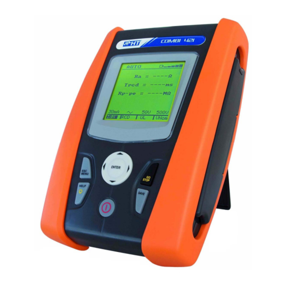
400 Series 4. NOMENCLATURE 4.1. INSTRUMENT DESCRIPTION CAPTION: 1. Inputs 2. Display 3. Connector for optoisolated cable 4. ,, , / ENTER key 5. GO/STOP key 6. SAVE key 7. ON/OFF key 8. HELP key 9. ESC/MENU key Fig. 1: Description of the front part of the instrument CAPTION: 1. -
Page 11: Keyboard Description
400 Series 4.3. KEYBOARD DESCRIPTION The keyboard includes following keys: ON/OFF key to switch on/off the instrument ESC key to exit the selected menu without confirming MENU key to activate menu management keys to move the cursor through the different screens in order to... -
Page 12: Main Menu
400 Series 5. MAIN MENU Pressing the MENU/ESC key in any allowable condition of the instrument displays the following screen, in which the instrument may be set, the saved measures can be displayed and the desired measuring function may be set. -
Page 13: Auto Power Off
400 Series 5.2.2. Auto Power OFF Move the cursor to Auto power off by means of the arrow O F F keys (,) and confirm with ENTER. Subsequently, the displays shows setting screen which allows enabling/disabling the auto power off of the instrument after a O N 5 m i n period of 5 minutes inactivity. -
Page 14: Operating Instructions
400 Series 6. OPERATING INSTRUCTIONS Press (short pressure) the key to activate the display’s backlighting should it be difficult to read the display. Press (long pressure) the HELP key to display an indicative scheme of the connections between the instrument and the system being tested in the function set Should more help screens be available for the same function, use the ... - Page 15 400 Series Press the MENU key, move the cursor to A U T O AUTO in the main menu by means of the R a = - - - - arrow keys (,) and confirm with ENTER. Subsequently the instrument displays a screen T r c d = - - - - m s similar to the one reported here to the side.
-
Page 16: Description Of Anomalous Results
400 Series CAUTION If message “Measuring…” appears on the display, the instrument is performing measurement. During this whole stage, do not disconnect the test leads of the instrument from the mains. Once the test is completed, if A U T O... - Page 17 400 Series If the measured phase-to- A U T O Value of earth resistance earth insulation value R a = 1 7 8 9 lower than the set limit, the Value of the RCD’s tripping time T r c d > 9 9 9 m s instrument displays a screen R P - P e = 0 .
- Page 18 400 Series If the instrument detects a A U T O phase-to-neutral voltage or a R a = - - - - phase-to-earth voltage higher than the limit, the message T r c d = - - - - m s reported here to the side is R P - P e = - - - - M ...
-
Page 19: Lowohm: Continuity Test Of Earth Leads With 200Ma
400 Series 6.2. LOWOHM: CONTINUITY TEST OF EARTH LEADS WITH 200mA This function is performed in compliance with standard IEC/EN61557-4 and allows measuring the resistance of protective and equipotential conductors. The following operating modes are available: CAL compensation of the resistance of the cables used for measurement. The instrument automatically subtracts the value of cable resistance from the measured resistance value. - Page 20 400 Series Use the , keys to select the parameter to be modified, and the , keys to modify the parameter value. It is not necessary to confirm the selection with ENTER. The virtual Func key allows setting the measuring mode of...
-
Page 21: Cal Mode
400 Series By using the AUTO mode, L O W once test is completed, in 0 . 2 5 Average value between R+ case average value and R- between R+ and R- is lower Values of the test currents for... -
Page 22: Description Of Anomalous Results
400 Series Once calibration is comple- L O W - - - - ted, in case the detected value is lower than 5, the instrument gives a double acoustic signal which signals - - - - - - - - ... - Page 23 400 Series If the instrument detects a L O W - - - - voltage value higher than 10V at the input leads, the screen reported here to the side is displayed - - - - - - - - ...
-
Page 24: M: Measurement Of The Insulation Resistance
400 Series 6.3. M: MEASUREMENT OF THE INSULATION RESISTANCE This function is performed according to standard IEC/EN61557-2 and allows measuring the insulation resistance between the active conductors and between each active conductor and the earth. The following operating modes are available: ... - Page 25 400 Series Use the , keys to select the parameter to be modified, and the , keys to modify the parameter value. It is not necessary to confirm the selection with ENTER. The virtual Func key allows setting the measuring mode of the...
-
Page 26: Description Of Anomalous Results
400 Series In case the TMR mode has been selected, pressing the GO/STOP key on the instrument or the START key on remote probe stops the test before the set time has elapsed. 10. Should the measured value M ... - Page 27 400 Series The results displayed can be saved by pressing the SAVE key twice or the SAVE key and, subsequently, the ENTER key (§ 8.1) If the instrument detects a M - - - M voltage of about 10V on the...
-
Page 28: Rcd: Test On A-Type And Ac-Type Rcds
400 Series 6.4. RCD: TEST ON A-TYPE AND AC-TYPE RCDS This function is performed in compliance with standard IEC/EN61557-6 and allows measuring the tripping time and the current of the system’s RCDs. The following operating modes are available: AUTO the instrument performs measurement automatically with a leakage current... - Page 29 400 Series Fig. 12: Instrument connection for 400V + N + PE three-phase RCD test by means of single cables and remote probe Fig. 13: Instrument connection for 400V + N (no PE) three-phase RCD test by means of single cables and remote probe Fig.
-
Page 30: Auto Mode
400 Series The virtual RCD key enables the selection of the RCD type, which may be: AC, AC S, A, A S (the options A, A S are not available if the electrical system set is IT) The virtual UL key allows setting the limit value of contact voltage... -
Page 31: Mode
400 Series While performing the test, R C D 0 ° 1 8 0 ° the instrument supplies a x 1 / 2 > 9 9 9 m s > 9 9 9 m s leakage voltage according to Tripping times of the RCD at the... -
Page 32: X1, X2, X5 Mode
400 Series If the RCD does not trip, the R C D 0 ° 0° or 180° type current instrument gives a double acoustic signal which signals Tripping time of the RCD > 999ms the positive result of the test... -
Page 33: Mode
400 Series 6.4.4. mode The standard defines the tripping times for RCDs at nominal current. The mode is used to detect the tripping time at tripping current (which could also be lower than the nominal voltage). As an alternative: Press the GO/STOP key on the instrument or the START key on remote probe once. -
Page 34: Ra Mode
400 Series 6.4.5. RA mode In RA mode, the contact voltage and the total earth resistance are measured by supplying a leakage voltage equal to half the value of the set nominal current in order to prevent the RCD from tripping. - Page 35 400 Series If the RCD does not trip R C D 0 ° within the maximum duration of the test, the instrument >999ms gives a long acoustic signal which signals the negative FRQ=50.0Hz Ut=1.4V result of the test and then...
- Page 36 400 Series If the instrument detects that R C D 0 ° the phase and neutral leads are inverted, the message ---ms reported here to the side is displayed. Rotate the shuko FRQ=50.0Hz Ut=1.4V plug or check the connection V P - N = 2 2 8 V...
- Page 37 400 Series 13. If the instrument detects an R C D 0 ° extremely high earth resistance, so that it deems ---ms the earth conductor or the earthing absent, it does not FRQ=50.0Hz Ut=1.4V perform the test and displays V P - N = 2 3 1 V...
-
Page 38: Loop: Measurement Of Line/Loop Impedance
400 Series 6.5. LOOP: MEASUREMENT OF LINE/LOOP IMPEDANCE This function is performed according to standard IEC/EN61557-3 and allows measuring the line impedance, the earth fault loop impedance and the prospective short circuit current. The following operating modes are available: P-N... - Page 39 400 Series Fig. 18: Instrument connection for 400V + N + PE three-phase P-P line impedance measurement by means of single cables and remote probe Fig. 19: Instrument connection for 400V + PE (no N) three-phase P-PE fault loop impedance measurement through single cables and remote probe...
-
Page 40: P-N Mode
400 Series The virtual RMT key, active only when the Z2Ω mode has been selected with the MOD key, displays the serial number and the FW version of the remote unit IMP57 If possible, disconnect all loads connected downstream of the measured point, as the impedance of these users could distort the test results. -
Page 41: P-P Mode
400 Series Formula used for calculating the prospective short circuit current: where: is the measured phase-to-neutral impedance is the nominal phase-to-neutral voltage = 127V if V ≤ 150V P-N meas = 230V or U = 240V (§ 5.2.3) if V >... -
Page 42: P-Pe Mode In Tt Or Tn Systems
400 Series 6.5.3. P-PE mode in TT or TN systems As an alternative: Press the GO/STOP key on the instrument or the START key on remote probe once. The instrument will start measuring with a “0°” type current, injecting a current in phase with the positive... -
Page 43: P-Pe Mode In It Systems
400 Series 6.5.4. P-PE mode in IT systems Press the GO/STOP key on the instrument or the START key on remote probe. The instrument will start the measurement. CAUTION If message “Measuring…” appears on the display, the instrument is performing measurement. During this whole stage, do not disconnect the test leads of the instrument from the mains. - Page 44 400 Series If the instrument detects that L O O P the phase and earth leads are inverted, the message ---- reported here to the side is - - - A displayed. Check FRQ=50.0Hz connection of the cables V P - N = 1 V...
- Page 45 400 Series By using the P-PE mode, if L O O P 0 ° the instrument detects that, in case the test should be ---- performed, a contact voltage - - - A higher than the set limit FRQ=50.0Hz would build up in the system...
-
Page 46: R A : Measurement Of The Total Earth Resistance Through The Socket-Outlet
400 Series 6.6. R MEASUREMENT OF THE TOTAL EARTH RESISTANCE THROUGH THE SOCKET-OUTLET This function is performed in compliance with standards IEC/EN61557-6 and allows measuring the impedance of the fault loop, comparable to the overall earth resistance in TT systems. One single operating mode is available. - Page 47 400 Series Press the MENU key, move the cursor to Ra in the main menu by means of the arrow keys (,) and confirm with ENTER. Subsequently ----- the instrument displays a screen similar to the - - - - A one reported here to the side.
-
Page 48: Description Of Anomalous Results
400 Series Formula used for calculating the prospective fault current: where: is the measured fault impedance is the nominal phase-to-earth voltage = 127V if V ≤ 150V P-PE meas = 230V or U = 240V (§ 5.2.3) if V >... - Page 49 400 Series If the instrument detects that the phase and earth leads are inverted, the message ---- reported here to the side is - - - A displayed. Check FRQ=50.0Hz connection of the cables V P - N = 1 V...
- Page 50 400 Series If the instrument detects an extremely high earth resistance, so that it deems ---- the earth conductor or the - - - A earthing absent, it does not FRQ=50.0Hz perform the test and displays V P - N = 2 3 1 V...
-
Page 51: 123: Phase Sequence Test
400 Series 6.7. 123: PHASE SEQUENCE TEST This function is performed in compliance with standards IEC/EN61557-7 and allows testing the phase sequence by direct contact with parts under voltage (no cables with insulating sheath). The following operating modes are available: ... - Page 52 400 Series CAUTION If message “Measuring…” appears on the display, the instrument is performing measurement. During this whole stage, do not disconnect the test leads of the instrument from the mains. The instrument switches to 1 2 3 stand-by mode and displays...
- Page 53 400 Series Fig. 27: Instrument connection for measuring the phase sequence with two leads, phase 2 connection When the instrument detects 1 2 3 a voltage higher than the minimum limit value on the test lead, the instrument displays the screen reported...
-
Page 54: Description Of Anomalous Results
400 Series 6.7.1. Description of anomalous results Once acquisition 1 2 3 completed, if the instrument has detected an uncorrect Correct phase sequence phase sequence, it displays a screen similar to the one reported here to the side and gives a long acoustic signal... - Page 55 400 Series AIR air speed by means of air-speed transducer RH air humidity by means of humidity transducer TMP °F air temperature in °F by means of thermometric transducer TMP °C air temperature in °C by means of thermometric transducer ...
-
Page 56: Air, Rh, Tmp °F, Tmp °C, Lux Mode
400 Series 6.8.1. AIR, RH, TMP °F, TMP °C, Lux mode Insert the connector of the probe being used into the instrument input In1 making sure that the probe connected and the set measurement unit correspond Press the GO/STOP key. The instrument stops... -
Page 57: Leak: Real Time Measurement Of The Leakage Current Through An External Clamp
400 Series 6.9. LEAK: REAL TIME MEASUREMENT OF THE LEAKAGE CURRENT THROUGH AN EXTERNAL CLAMP Using an external clamp, this function allows measuring the leakage current. Fig. 29: Indirect measurement of leakage current in three-phase systems Fig. 30: Direct measurement of leakage current in three-phase systems... -
Page 58: Description Of Anomalous Results
400 Series CAUTION Possible additional earth connections could influence the measured value. For the difficulty of this measurement and the sometimes real difficulty in removing the clamps, we recommend performing the measurement indirectly. Press the GO/STOP key. The instrument stops... -
Page 59: Mains Analysis
400 Series 7. MAINS ANALYSIS 7.1. PWR: REAL TIME MEASUREMENT OF THE MAINS PARAMETERS This function allows measuring the voltage of the electrical mains and of the relevant harmonics. Using an external clamp, it is also possible to measure the current and the relevant harmonics as well as other electrical parameters such as power, power factor, etc. -
Page 60: Par Mode
400 Series The virtual FS key, active only when the HRM V or the HRM I mode has been selected with the Func key, allows increasing or decreasing the ordinal harmonic number whose value is displayed Insert the clamp connector into the instrument input In1 Staple the phase to be tested. -
Page 61: Memory
400 Series 8. MEMORY 8.1. HOW TO SAVE A MEASURE When the SAVE key is first S A V E pressed, as described in the First available memory location (last M e m o r y : 0 1 5 saved + 1) §s regarding the different... -
Page 62: Saved Data Management
400 Series 8.2. SAVED DATA MANAGEMENT Press the MENU key, move the cursor to MEM M E M in the main menu by means of the arrow keys M E M T I P O L O W 0 0 1... -
Page 63: How To Delete The Last Measure Or All Of Them
400 Series 8.2.2. How to delete the last measure or all of them By means of the CANC virtual key select LST C L R or TOT whether you want to delete the last measure or all the measures in the memory. -
Page 64: Connecting The Instrument To The Pc
400 Series 9. CONNECTING THE INSTRUMENT TO THE PC CAUTION The connection between instrument and PC is realized by means of cable C2006. In order to transfer the data onto a PC it is necessary to install beforehand both the management software Topview and the drivers of cable C2006 on the PC itself. -
Page 65: Maintenance
400 Series 10. MAINTENANCE 10.1. GENERAL The instrument you purchased is a precision instrument. When using and storing it, please observe the recommendations listed in this manual in order to prevent any possible damage or danger. Do not use the instrument in environments with high humidity levels or high temperatures. -
Page 66: Specifications
400 Series 11. SPECIFICATIONS Accuracy indicated as: ±[%rdg + (num. dgt * resolution)] at 23°C, <80%RH. Refer to the Table 1 for the correspondence between models and available functions 11.1. TECHNICAL FERATURES Continuity test (LOW) Accuracy Range [] Resolution [] 0.00 ... - Page 67 400 Series Tripping current ( ) IdN [mA] Type Range IdN [mA] Resolution [mA] Accuracy (0.5 1.1) IdN ≤ 10 (0.3 1.1) IdN 0.1IdN -0%, +10%rdg (0.5 1.1) IdN > 10 (0.3 1.1) IdN RCD type:...
- Page 68 400 Series Environmental parameters (AUX) Transduced Parameter Range Resolution Accuracy signal -20.0 80.0°C -20 +80mV 0.1°C Temperature -4.0 176.0°F -4 +176mV 0.1°F 0.0 100.0% RH 0 +100mV Humidity 0.1% RH (0.0 999.9mV) (0.2 999.9mV) (2.0rdg + 2dgt)
- Page 69 400 Series Measurement of the active, reactive and apparent power @ Vmis>60V, cos=1, f=50.0Hz Clamp full scale Range [W, VAR, VA] Resolution [W, VAR, VA] Accuracy 0.0 999.9 FS ≤ 1 1.000 9.999 k 0.001 k 0.000 9.999 k 0.001 k...
-
Page 70: Reference Guidelines
400 Series 11.2. REFERENCE GUIDELINES 11.2.1. General Instrument safety: IEC/EN61010-1, IEC / EN61557-1, -2, -3, -4, -6, -7 Technical documentations: IEC/EN61187 Accessory safety: IEC/EN61010-031, IEC/EN61010-2-032 Insulation: double insulation Pollution level: Max height of use: 2000m (6562ft) Overvoltage category: CAT III 240V to earth, max 415V among inputs P, N, PE 5V to ground, max 7.2V... -
Page 71: Service
400 Series 12. SERVICE 12.1. WARRANTY CONDITIONS This instrument is guaranteed against any defect in material and manufacturing in compliance with the general sales terms and conditions. Throughout the period of guarantee all defective parts may be replaced and the manufacturer reserves the right to repair or replace the product. -
Page 72: Practical Reports For Electrical Tests
400 Series 13. PRACTICAL REPORTS FOR ELECTRICAL TESTS 13.1. CONTINUITY MEASUREMENT ON PROTECTIVE CONDUCTORS 13.1.1. Purpose of the test Check the continuity of: Protective conductors (PE), main equalizing potential conductors (EQP), secondary equalizing potential conductors (EQS) in TT and TN-S systems ... -
Page 73: Insulation Resistance Measurement
400 Series 13.2. INSULATION RESISTANCE MEASUREMENT 13.2.1. Purpose of the test Check that the insulation resistance of the installation complies with the requirements of IEE 16 edition standard. EXAMPLE OF INSULATION MEASUREMENT ON AN INSTALLATION Fig. 33: Insulation measurements on an installation The switches D and E are those installed near the load having the purpose of separating it from the installation. - Page 74 400 Series Switch situation Point under test Measurement Judgment on the installation Effect the OK ( If R end of the test A, D Turn the switch LIMIT measurement on and E off If R 2 Proceed switch LIMIT ...
- Page 75 400 Series ALLOWABLE VALUES Rated circuit voltage Test voltage Insulation resistance (M) 0.250 SELV and PELV* 1.000 Up to 500 V included, except for the above circuits. 1.000 Over 500 V 1000 * In the new standards the terms SELV and PELV replace the old definitions "safety low voltage"...
-
Page 76: Check Of The Circuit Separation
400 Series 13.3. CHECK OF THE CIRCUIT SEPARATION 13.3.1. Definitions A SELV system is a system of category zero or very low safety voltage featured by: autonomous source (ex. batteries, small generator) or safety (ex. safety transformer) power supply, protection separation to other electrical systems (double or reinforced insulation or a metal screen connected to the earth) and no earthed points (insulated from the earth). - Page 77 400 Series EXAMPLE OF CHECKING THE SEPARATION AMONG ELECTRICAL CIRCUITS Insulation or safety transformer separating the circuits TEST BETWEEN ACTIVE PARTS Connect an instrument probe to one of the two conductors of the separated circuit and the other to one of the conductors of a non-...
-
Page 78: Working Test Of Rcds
400 Series 13.4. WORKING TEST OF RCDS 13.4.1. Purpose of the test Check whether general and selective RCDs have been installed and adjusted properly and whether they maintain their features over the time. The check shall confirm that the RCD... -
Page 79: Test Of Rcd Tripping Current
400 Series Before effecting the test at the RCD rated current the instrument carries out a test at ½IdN to measure the contact voltage and the overall earth resistance; if during this test the RCD trips an error message is displayed. During this test the RCD may trip for three possible reasons: ... -
Page 80: Measurement Of Short-Circuit Impedance
400 Series 13.6. MEASUREMENT OF SHORT-CIRCUIT IMPEDANCE 13.6.1. Purpose of the test Check that the tripping power of the protection device is higher than the maximum fault current of the installation. 13.6.2. Installation parts to be checked The test shall be effected in the point where the short circuit current is the highest possible, usually immediately downstream the RCD to be checked. -
Page 81: Earth Resistance Measurementin Tt Systems
400 Series 13.8. EARTH RESISTANCE MEASUREMENTIN TT SYSTEMS 13.8.1. Purpose of the test Check that the RCD is coordinated with the earth resistance value. It is not possible to assume an earth resistance value as reference limit when controlling the test result, while it is necessary to check every time that the co-ordination complies with the requirements of the standards. -
Page 82: Voltage And Current Harmonics
400 Series 13.9. VOLTAGE AND CURRENT HARMONICS 13.9.1. Theory Any periodical non-sine wave can be represented as a sum of sinusoidal waves having each a frequency that corresponds to an entire multiple of the fundamental, according to the relation: ... -
Page 83: Presence Of Harmonics: Causes
400 Series Odd harmonics Even harmonics Not multiple of 3 Multiple of 3 Relative voltage % Order h Relative voltage Order h Relative voltage Order h % Max % Max 6..24 Table 6: Limits for the harmonic voltages the supplier may introduce into the network... -
Page 84: Power And Power Factor Definition
400 Series 13.9.4. Presence of harmonics: consequences In general, even harmonics, i.e. the 2 etc., do not cause problems. Triple harmonics, odd multiples of three, are added on the neutral (instead of cancelling each other) thus creating a condition of overheating of the wire which is extremely dangerous. Designers... -
Page 85: Note
400 Series In presence of distorted voltages and currents the previous relations vary as follows: Phase active power: (n=1,2,3) Phase reactive power: (n=1,2,3) Phase apparent power: (n=1,2,3) Phase power factor: ... - Page 86 400 Series Equipment under test = inductive generator Equipment under test = capacitive load 90° Pfc+ = -1 Pfc- = -1 Pfc- = -1 Pfc+ = Pf Pfi+ = -1 Pfi- = -1 Pfi- = Pf Pfi+ = -1 180°...
- Page 88 Via della Boaria 40 48018 – Faenza (RA) - Italy Tel: +39-0546-621002 (4 linee r.a.) Fax: +39-0546-621144 email: ht@htitalia.it http://www.ht-instruments.com...
Need help?
Do you have a question about the 400 Series and is the answer not in the manual?
Questions and answers