Table of Contents
Advertisement
Quick Links
Advertisement
Table of Contents

Related Manuals for Eighteeth E-connect S+


Summary of Contents for Eighteeth E-connect S+
- Page 1 E-connect S+ Endo Motor USER MANUAL Changzhou Sifary Medical Technology Co.,Ltd.
- Page 2 P/N:IFU-6035231 Version:S01 Issued:Mar,9,2022 Size:160mm*92mm...
-
Page 3: Table Of Contents
Content 1. Scope of E-connect S+ ..................... 4 1.1 Parts Identification .................... 4 1.2 Components and Accessories ................5 1.3 Options ......................5 2. Symbols used in the User Manual ................6 3. Before Use ........................ 7 3.1 Intended Use ....................7 3.2 Contraindications.................... -
Page 4: Scope Of E-Connect S
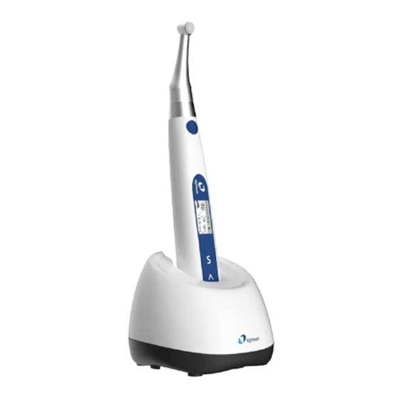
1 Scope of E-connect S+ 1. Scope of E-connect S+ 1.1 Parts Identification 2 2 2 2 2 1 Contra Angle 2 Motor Handpiece 3 Charging Base Note: This product does not contain root canal file 4 Insulating Sleeve 5 File Clip (2 pcs) 6 Lip Hook (2 pcs) 7 Measuring Wire 8 Adapter... -
Page 5: Components And Accessories
1 Scope of E-connect S+ 1.2 Components and Accessories Motor Handpiece Charging base Contra Angle (1pcs) (1pcs) (1pcs) Adapter (1pcs) Spray Nozzle Measuring Wire (1pcs) (1pcs) Lip Hook (2pcs) File clip (2pcs) Insulating Sleeve (1pcs) Apex Tester (1pcs) Certificate (1pcs) Warranty card (1pcs) 1.3 Options Handpiece Base... -
Page 6: Symbols Used In The User Manual
2 Symbols used in the User Manual Symbols used in the User Manual If the instructions are not followed properly, operation may WARNING lead to hazards for the product or the user/patient. Additional information, explanation operation NOTE performance. Serial number Catalogue number Manufacturer Date of manufacture... -
Page 7: Before Use
3 Before Use 3. Before Use 3.1 Intended Use E-connect S+ is a cordless endodontic treatment motorized handpiece with root canal measuring capability. It can be used to enlarge canals while monitoring the position of the file tip inside the canal. It can be used as a low speed motorized handpiece and device for measuring canal length. - Page 8 3 Before Use RF communications device (including peripherals such as antenna cables and external antennas) should be used no closer than 30 cm (12 inches) to any part of the E-connect S+, including cables specified by the manufacturer. Otherwise, degradation of the performance of this device could result.
-
Page 9: Installing The E-Connect S
4 Installing the E-connect S+ 4. Installing the E-connect S+ 4.1 Installation of the contra angle Make sure 4 pins on contra angle alignment the slots of handpiece, plug them together until a sound of “click” to make sure to install into place. -
Page 10: Installation Of The Insulating Sleeve
4 Installing the E-connect S+ WARNING NOTE 1. Check the file before inserting the Without the insulating sleeve, file. Do not use the damaged file. when performing the apex me- 2. Pull the file gently to make sure asurement with handpiece, we- that the file is secure in handpiece ar appropriate insulated gloves, properly, otherwise it may pop out... -
Page 11: Connecting Charge Base
4 Installing the E-connect S+ Put the handpiece all the way NOTE into the charge base, the charge state will show on the Match colors to connect the lip screen. hook and file clip, if connect lip hook with black slot, apex auto start will have no function. - Page 12 4 Installing the E-connect S+ If only need a base to put the device on dentist element of dental chair ( without charge function ), handpiece base is recommended ( sold separately ) to instead of charge base. 12 / 61...
-
Page 13: Use Interface
5 Use Interface Power on 5.Use Interface Press more than 0.5 seconds to turn on the instrument. 5.1 Panel key Memory Change Press < > to change at standby mode. Operation Mode Change Press once at standby mode, press < >... -
Page 14: Screen Display
5 Use Interface 5.2 Screen display Standby interface ① Memory name ② Speed ③ Voice ④ Residual battery power Myfile ⑤ Unit of speed (Revolutions Per 300rpm Minute) 3.0N cm F WD ⑥ Unit of torque (Newton Centimeter) ⑦ Torque ⑧... - Page 15 5 Use Interface Canal measurement standby interface ① Memory mode number M0 is apex stand-alone memory Canal measurement start interface ② Indication number The number has no represent of actual length, only for indication ③ Canal length indicator bar 15 / 61...
-
Page 16: Terms And Definition
5 Use Interface 5.3 Terms and definition Forward (Clockwise rotation) Reverse (Counter clockwise rotation) Reciprocation Be applied to reciprocating file, path file and rotary file protection by setting some special angle Adaptive torque control Up to setting torque, the motor will move with reciprocating mode;... -
Page 17: Setting
6 Setting 6.Setting 6.1 Set memory mode The device has 10 memory modes (M1-M10), press < > at standby mode to switch, the memory number (①) will change together. Myfile 300rpm Each memory mode includes 3.0N cm its own speed (②), operate mode(④) and torque(③). -
Page 18: Setting Parameters
6 Setting 6.2 Setting parameters WARNING All the parameters must be set according to files, make sure all the parameters are expected before starting the motor, otherwise has risk of file broken. Before starting the motor, check whether the operation mode (①) is correct. If it is not the expected operation mode, press Myfile once on to enter the operation mode... - Page 19 6 Setting Speed can be set from 50 rpm to 1500 rpm. Press several times at standby mode till speed is displayed. Press < > to switch and press or wait for 5 seconds to confirm. Speed Set NOTE When using REC mode, there are five 200 rpm speed can be set (100rpm ~ 500rpm).
- Page 20 6 Setting E-connect S+ integrated apex locator, if the lip hook is connecting with patient’s lip, when the endo file entering root canal, the motor will start automatically. Press < > to shut off this function ● if not expected, press to start and stop Auto Start the motor.
- Page 21 6 Setting reference point. During combined length determination, normally apical reverse must active before Reference Point Reference Point reaching major apical foramen, Press < > to set apical reverse position by change the flash bar (①), the motor will reverse while reaching the flash bar every time.
-
Page 22: Preset Programs
6 Setting 6.3 Preset programs For convenience, we preset some common file system. Long press to entry preset program during standby state, the interface will show as left. New File (①) Indicates a new folder. You Myfile Protaper can use this function to create a mode. Hyflex Myfile (②) represents the current memory mode. - Page 23 6 Setting In new mode, continue to press Speed Set enter the Speed Setting mode. Press 200 rpm < > to select a speed from 50rpm to 1500rpm, and press to confirm. In the new mode, continue to press to enter the "Torque Setting" mode, press Torque Limit Back light <...
- Page 24 6 Setting ® ® 2Shape and OneCurve are registered trademarks of Micro-Mega, Inc.; ® ® XPendo.Shaper , XPendo.Finisher ® ® ® iRace , BT-Race and BioRace registered trademarks of FKG Corporation. E-flex is our file needle Some preset modes, such as Flex.Master(①), can be set to different Flex.Mast er 280rpm 0.5N cm...
- Page 25 6 Setting parameters will be reset and the mark will disappear. If want to change back to default setting, long press to entry preset program during standby state, select “OneCurve” and press to confirm, the default setting will be recalled, and the 4 corners around will disappear.
-
Page 26: Advanced Setting
6 Setting 6.4 Advanced setting Versions ● Hold then press for about 0.5 seconds at power off mode will enter S+ 1 advanced setting, the version will display. Press S again, the “Auto Power Off” Auto Power Off time can be change, press <... - Page 27 6 Setting In the advanced setting mode, press Back light again to enter the "Backlight Setting" interface, where you can set the backlight intensity. Press < > to adjust and press to confirm. Press again, the “Habit hand” can be change, press <...
- Page 28 6 Setting Press again, entry“Calibration” function, press < > to select ● “ON”, press to start calibration. WARNING Calibration ● Before calibrating, making sure the original contra angle is installed, and do not install the file. ● The torque will not correct if calibration without original contra angle or any load on contra angle chuck, and has risk of file broken.
-
Page 29: Parameter Logic
6 Setting 6.5 Parameter logic The factory default parameters of the ten memory modes are shown in the table below. The parameters can be adjusted as needed. Parameter M9 M10 Operation APEX Fwd Fwd REC REC ATC Rev Rev Fwd Fwd mode Speed 300 400 350 350... - Page 30 6 Setting Speed (rpm) settings are different at different operation modes. See the table below for details. 1000 1100 1200 1300 1400 1500 Torque (N·cm) settings are different at different operation modes. Even at the same operation mode, the torque settings will be limited by the speed settings.
- Page 31 6 Setting Fwd angle (°) and Rev angle (°) settings are different at different operation modes. See the table below for details. Fwd Rev same angle with the left table same The same with the front table with the angle front table NOTE...
-
Page 32: Operation
7 Operation 7. Operation 7.1 Charge The left figure on the top left of the screen shows the remaining battery level. When it turns right as shown left means low battery, please charge in time. NOTE 1. If the battery level is less than 15%, it must be recharged within 30 days, otherwise the battery will be irretrievably damaged due to low power. - Page 33 7 Operation When not using charging base, connecting the adapter directly to the device can also charge the device, and charging mode will display on the screen. Charging base is recommended for charging (Refer to chapter 4.4 Connect the charging base). NOTE Please use the original power adapter Charging mode will display on the screen...
-
Page 34: Motor Operation
7 Operation surface covered with film. The device should be placed where it is easy to charge and operate disconnected device. 7.2 Motor Operation Press at standby mode to start the motor, then the torque bar will display on 300rpm 3.0N c m ·... - Page 35 7 Operation NOTE 1. When there is any abnormality, please stop using the device. This device is not suitable for all types of root canals. It is recommended to use according to the instructions of root canal file. 2. The root canal file is easy to fracture at high speed. Please follow the rotation speed recommended by the manufacturer.
-
Page 36: Apex Operation And Not Suitable Condition
7 Operation 7.3 Apex operation and not suitable condition When using as a stand-alone apex locator. We suggest put the handpiece on the charge base to get better visual angle. the measure wire must be connecting with motor by USB socket, white slot connects with lip by lip hook, and black slot connect with file clip. - Page 37 7 Operation then release the button. The file clip must be nearly vertical with file handle, otherwise will damage the tip of the file holder. NOTE We recommend using Apex Tester to check the accuracy of apex locator every time before use.
- Page 38 7 Operation Root canal with a large apical foramen The root canal cannot be accurately measured because of the lesion or incomplete development of the apical foramen. The results may show that the length measured is shorter than the actual one. Root canal blood overflow from the opening If blood spills from the root...
- Page 39 7 Operation Broken crown Build-up (e.g. cement) If the crown is broken, a segment of the gingival tissue enters the lumen, and the contact between the gingival tissue and the root file causes electrical leakage, which cannot be accurately measured. In this case, the appropriate material should be used to isolate the gingival tissue.
- Page 40 7 Operation Crown or metal prosthesis Crown that touches gingival tissue Accurate measurement cannot be obtained if the file touches a mental prosthesis that is touching gingival tissue. In this case, widen the opening at the top of the crown so that the file will not touch the mental prosthesis before taking a measurement.
- Page 41 7 Operation Extremely dry canal If the canal is extremely dry, the meter may not work until it is quite close to the apex. In this case, try to moisten the Too dry canal with oxydol or saline. Difference measuring result between Apex locator reading and Radiography Sometimes the reading of the apex locator reading does not correspond to the X-ray image.
-
Page 42: Cleaning, Disinfection And Sterilization
8 Cleaning, Disinfection and Sterilization 8. Cleaning, Disinfection and Sterilization 8.1 Foreword For hygiene and sanitary safety purpose, the components (contra angle, and insulating sleeve) must be cleaned, disinfected and sterilized before each usage to prevent any contamination. This concerns the first use as well as the subsequent uses. -
Page 43: Autoclavable Components
8 Cleaning, Disinfection and Sterilization 8.3 Autoclavable Components Autoclavable Components Contra Angle Lip Hook File clip Insulating Sleeve WARNING 1. Only the components above can be autoclaved. 2. Before first use and after each use, sterilize the above components. Reprocessing Instructions Disconnect the components (Contra Angle, Insulating Sleeve) from the handpiece. - Page 44 8 Cleaning, Disinfection and Sterilization area to avoid any damage and contaminate on to the environment. The devices must be reprocessed in a disassembled state. Preparation for WARNING Decontaminatio 1. Do not fail to take out the file before cleaning the contra angle.
- Page 45 8 Cleaning, Disinfection and Sterilization The automated cleaning processes have been validated by using 0.5% neodisher MediClean forte (Dr. Weigert). Note Acc. to EN ISO 17664 no manual reprocessing methods are required for these devices. If a manual reprocessing method has to be used, please validate it prior to use.
- Page 46 8 Cleaning, Disinfection and Sterilization Functional Visual inspection for cleanliness of the instruments Testing, and reassembling. Functional testing according to Maintenance instructions of use. If necessary, perform reprocessing process again until instrument is visibly clean. Before packaging and autoclaving, make sure that the components have been maintained acc.
- Page 47 8 Cleaning, Disinfection and Sterilization Sterilization Sterilization of instruments by applying a fractionated pre-vacuum steam sterilization process (according to EN 285/EN 13060/EN ISO 17665) under consideration of the respective country requirements. Minimum requirements: 3 min at 134 °C (in EU: 5 min at 134 °C) Maximum sterilization temperature: 137°C Flash sterilization is not allowed on lumen instruments!
-
Page 48: Disinfection Components
8 Cleaning, Disinfection and Sterilization WARNING The instructions provided above have been validated by the manufacturer of the medical device as being capable of preparing a medical device for use. It remains the responsibility of the processor to ensure that the processing, as actually performed using device, materials and personnel in the processing facility, achieves the desired result. -
Page 49: Error Warning
9 Error warning 9. Error warning When motor is running in over torque reversing or R.L. torque set mode, if the load exceeds the device limit, this Ove rload warning will appear on the screen. R esta r Mot or Press to leave this page to return to standby mode. -
Page 50: Troubleshooting
10 Troubleshooting 10. Troubleshooting When trouble occurs, check this chart before contacting your distributor. If none of these are applicable or the trouble is not remedied even after action has been taken, the product may have failed. Contact your distributor. Problem Cause Solution... - Page 51 10 Troubleshooting damaged hand piece for charging and contact the dealer. Try to power on the device normally to check if there is any Screen beep sound. If so, Screen does does not press the main switch not work display again to watch whether the motor run.
- Page 52 10 Troubleshooting Motor rotation Operation Check the operation direction mode is REC or mode set changs frequently No beep Beep volume is Check the beep sound “0” volume set Operation Beep all mode is REC or Check the operation the time torque set is set or torque set R.L.
-
Page 53: Technical Data
11 Technical Data 11. Technical Data Manufacturer Changzhou Sifary Medical Technology Co., Ltd. Model E-connect S+ Dimensions 20.1cm x 10.6cm x 11.5±1cm (Outer box) Weight 0.89kg±10% Compatible with rotary and reciprocating instruments, equipped with 2.35mm nickel Contra angle titanium root canal file conforming to ISO 1797:2017, Type 1, Files length 11-31mm. -
Page 54: Emc Tables
12 EMC Tables 12. EMC Tables Guidance and manufacturer’s declaration - electromagnetic emissions The E-connect S+ is intended for use in the electromagnetic environment specified below. The customer or the user of the E-connect S+ should assure that it is used in such an environment. Complianc Electromagnetic environment Emissions test... - Page 55 12 EMC Tables Guidance and manufacturer’s declaration – electromagnetic immunity The E-connect S+ is intended for use in the electromagnetic environment specified below. The customer or the user of the E-connect S+ should assure that it is used in such an environment. Immunity IEC 60601 test Compliance...
- Page 56 12 EMC Tables Mains power quality 0% UT; 0.5 0% UT; 0.5 should be that of a cycle cycle typical commercial at 0°, 45°, 90°, at 0°, 45°, 90°, or hospital 135°, 180°, 135°, 180°, Voltage environment. If the 225°, 270°, and 225°, 270°, and dips user of devices...
- Page 57 12 EMC Tables Guidance and manufacturer’s declaration – electromagnetic immunity The E-connect S+ is intended for use in the electromagnetic environment specified below. The customer or the user of the E-connect S+ should assure that it is used in such an environment. Electromagnetic IEC 60601 test Complia...
- Page 58 12 EMC Tables Recommended minimum separation distances Nowadays, many RF wireless equipment has being used in various healthcare locations where medical equipment and/or systems are used. When they are used near medical equipment and/or systems, the medical equipment and/or systems’ basic safety and essential performance may be affected.
- Page 59 12 EMC Tables GSM 1800; CDMA 1720 1900; GSM 1900; Pulse 1700- DECT; modulation 1990 LTE Band 217Hz 1845 1, 3, 4, 25; 1970 UMTS Bluetooth, WLAN, Pulse 2400- 802.11 2450 modulation 2570 b/g/n, 217Hz RFID 2450, LTE Band 7 5240 WLAN Pulse...
-
Page 60: Statement
13 Statement 13.Statement Service Life The service life of E-connect S+ series products is 3 years. It is recommended that the equipment be checked and repaired at the dealer once a year. Maintenance MANUFACTURER will provide circuit diagrams, component part lists, descriptions, calibration instructions... - Page 61 Changzhou Sifary Medical Technology Co., Ltd. Add: NO.99, Qingyang Road, Xuejia County, Xinbei District, Changzhou City, 213000 Jiangsu, P.R. China Tel: +86-0519-85962691 Fax: +86-0519-85962691 Email: Info@sifary.com Web: www.sifary.com Caretechion GmbH Tel: +49 211 2398 900 Add: Niederrheinstr. 71, 40474 Duesseldorf, Germany Email: info@caretechion.de All rights reserved.
Need help?
Do you have a question about the E-connect S+ and is the answer not in the manual?
Questions and answers