Table of Contents
Advertisement
Quick Links
Advertisement
Chapters
Table of Contents

Related Manuals for ATTACK ATTACK DPX COMBI PELLET Series


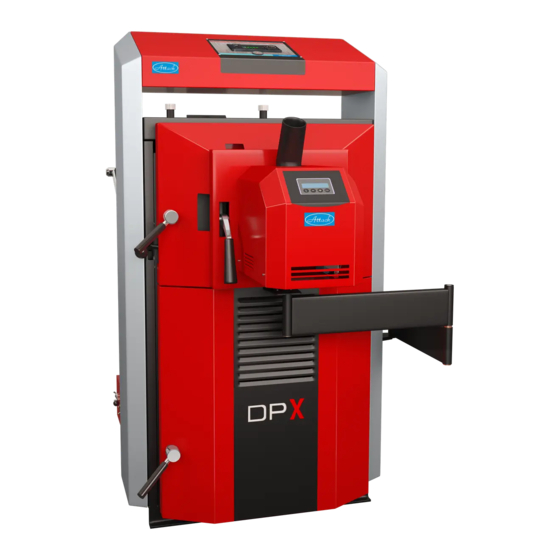
Summary of Contents for ATTACK ATTACK DPX COMBI PELLET Series
- Page 1 EN 07/2019 ATTACK DPX COMBI PELET Instructions for use www.attack.sk...
-
Page 3: Table Of Contents
HEATING UP AND OPERATION ......................21 OPERATION OF BOILER ATTACK DPX COMBI PELLET ................23 OPERATION OF BOILER ATTACK DPX COMBI PELLET – WOOD MODE ........24 ADVANTAGES OF THE REGULATOR ....................25 BASIC DESCRIPTION OF THE REGULATOR ..................25 CONNECTION OF THE REGULATOR BY HYDRAULIC SCHEMES.......... - Page 4 7.13 OPERATION WITH PERMANENT BURNING ..................38 BURNER ASSEMBLY TO THE BOILER ......................39 OPERATION OF BOILER ATTACK DPX COMBI PELLET – PELLETS MODE ........40 ATTACK PELLET BURNER AUTOMATIC 8–30 KW ................43 ATTACK PELLET BURNER AUTOMATIC 15–50 KW ................. 44 BURNERS DIMENSIONS ..........................
-
Page 5: Introduction
Dear customer, thank you for your trust and purchase of our product – the ATTACK COMBI Pellet boiler. We wish it serves you reliably for a long time. The reliable and correct function of device is related to its opera- tion and therefore it is necessary to read this user manual. -
Page 6: Important Information
The warranty for the boiler is not valid: • if it is not operated with the prescribed fuel. • if no mixing device Regumat ATTACK–OVENTROP is installed in the system to ensure the re- turn water temperature of at least 65 °C during the boiler operation. -
Page 7: Safety
1.5 FUEL 1.5.1 WOOD The ATTACK DPX COMBI Pellet can be used soft and hard chopped firewood with a heat value 15 – 17 MJ/kg. Ideal are especially beech, oak, fir, spruce, pine, poplar, alder, willow, birch, ash, hornbeam, acacia, each with a moisture 12 – 20 %. A suitable diameter of the logs is 80 –... -
Page 8: Pellets
Recommended storage and drying of wood: Hard wood: 2 years stored in a dry place Soft wood: 1 year stored in a dry place Wood during storage (drying) must be protected against rain. Effective drying of wood can help,that the wood will be saved with the largest possible air gaps. Then air can flow between the pieces of wood. -
Page 9: Assembly And Installation Of The Boiler
2 ASSEMBLY AND INSTALLATION OF THE BOILER 2.1 MANIPULATION WITH THE BOILER The boiler is delivered on pallet. Manipulation with the boiler always perform on the pallet. Only if is boiler on installation place, remove the boiler from the pallet. This can be done with the help of a handling truck or a crane and hanging ears, which are welded to the heat exchanger of the boiler. -
Page 10: Binding Norms For Projecting And Installation Of The
2.2.1 BINDING NORMS FOR PROJECTING AND INSTALLATION OF THE BOILERS Boiler installation must meet the following norms: STN EN 303–5:2012 Heating boilers for solid fuels STN 73 42 10 Construction of the chimneys and flue connections STN EN 60 335.1 +A11 Safety of the electrical appliances for household STN EN 12828+A1 Heating systems in buildings. -
Page 11: Placing The Boiler
2.3 PLACING THE BOILER The boiler is intended to be installed and operated in the premises with the basic environment (AA5/AB5) following the STN 33 2000–1:2009–04. Boiler room must meet also the following conditions: • The boiler room must not be potentially explosive environments, due to the fact that the boiler is not suitable for use in such environments. -
Page 12: Boiler Connection To The Heating System
2.4 BOILER CONNECTION TO THE HEATING SYSTEM Boiler ATTACK DPX COMBI Pellet must be installed in system complying with the quality of heat- ing water as follows: Slovak Republic: STN 07 7401:1991 Austria: ONORM H5195–1 Germany: VDI 2035 Switzerland: SWKI 97–1 Italy: D.P.R. -
Page 13: Chimney
ATTENTION: If is not installed in the system equipment against condensation, or the equipment will not operate properly, can result in the formation of aggressive conden- sate. It lead to boiler damage. Protection against condensation must be used during operation of the boiler, otherwise it will void warranty by the manufacturer! 2.4.3 CHIMNEY Connection of the appliance to the chimney hole must be always done with permission of the appropriate chimney sweep association. -
Page 14: Connection With External Pellet Tank And Pellet Feeder
To the boiler ATTACK DPX COMBI Pellet is recommend to use ATTACK pellet tank in combination with screwed ATTACK pellet feeder, length about 2 m. Pellet tank is possible to place on the right or the left side of the boiler, where necessary. For 30 kW burner there is recommend- ed PED200 feeder. -
Page 15: Burner Connection To The Boiler And Boiler Temperature Sensor
2.4.7 BURNER CONNECTION TO THE BOILER AND BOILER TEMPERATURE SENSOR Burner is connected to the boil- er by cable with 6–pin connect- or that comes from the feet of the boiler, at the point where pantograph arm is fixed. The cable is necessary after assem- bly to attach to the arm of the pantograph by supplied plastic... -
Page 16: Boiler Protection Against Overheating
Recommended capacity of accumulation tank for boiler ATTACK DPX COMBI Pellet is 50 l per 1 kW boiler output, the minimum capacity is 25 l per 1 kW boiler output. When choosing a capacity of accumulation tank, it is necessary to have on mind that the size of the accumula- tion tank affects on operation of the boiler. - Page 17 It should be noted that the above is only relevant in the operation of boiler with WOOD. In operation of PELLETS it loses meaning, the boiler need not be connected to the accumu- lation tank, but the boiler have to operate always only with PELLETS. The ATTACK accumulation tanks available* TUVS —...
-
Page 18: Techn. Parameters For Attack Dpx Combi Pellet
Range of setting the temp. of heating water 230/2 Capacity of contacts of the boiler regulator Connection to the heating system " G6/4" G2" Producer, the ATTACK, s.r.o., reserves right to make technical changes of products without the previous announcement! -
Page 19: Dimensions Of Boiler Attack Dpx Combi Pellet
4 DIMENSIONS OF BOILER ATTACK DPX COMBI PELLET DPX 25CP DPX 30CP DPX 35CP DPX 40CP DPX 45CP DPX 50CP Flow connection „B“ G 6/4" G 6/4" G 6/4" G 2" G 2" G 2" Return connection „A“ G 6/4"... -
Page 20: Purpose Of Use
5 PURPOSE OF USE The ecological warm water boiler ATTACK DPX is intended for heating the family houses and other similar objects. The boiler is designed only for the use of wood logs. Any type of dry wood can be used, especially the wood logs. It is also possible to use the blocks of wood with larger diameter –... -
Page 21: Technical Description
On the console are pins which attached two arms of the pantograph, with burner door and the burner. ATTACK PELLET BURNER Automatic 8 – 30 kW or 15 – 50 kW works on basis of the fuel feeding by the principle of falling, when the pellets fall by from the pellet feeder through the inlet hose and the inlet tube on the grate, where they are burned. -
Page 22: Technical Description Of Attack Dpx Combi Pellet
6.1 TECHNICAL DESCRIPTION OF ATTACK DPX COMBI PELLET 6.1.1 OPERATING PRESCRIPTIONS Boiler preparation for operation Before starting the boiler, it is necessary to check that the system is filled with water, deaerated and the pressure of heating water does not decrease. Make sure that the sensors of the boiler, safety thermostat and manometer are placed in casings on the upper rear side of the boiler. - Page 23 ATTENTION: The pull rod of the heat up flap has to be pushed backwards to close the heat up flap. Otherwise the fan could get damaged! For wood gasification in the boiler it is necessary to keep the reduction layer during the opera- tion (the layer of wood coal on the nozzle in the feeding chamber).
-
Page 24: Operation Of Boiler Attack Dpx Combi Pellet
7 OPERATION OF BOILER ATTACK DPX COMBI PELLET The PROFI PID electronics is located on the front side of the control panel, where the main boiler switch is located. In the pictures below you can see the basic and safety features of the control panel. -
Page 25: Operation Of Boiler Attack Dpx Combi Pellet - Wood Mode
The boiler temperature is at the level set by the enduser, to control the flue gas fan rotations. ATTACK boiler regulator measures the temperature of the water in the boiler all the time and the value shows on the display with improved controller for flue gas temperature by PID. Based on this value, the controller controls the fan rotations and pump of central heating. -
Page 26: Advantages Of The Regulator
7.2 ADVANTAGES OF THE REGULATOR The regulator can control: 1. Rotations of flue gas fan 2. Circuit pump of heating circuits 3. Pump for warming the D.H.W. or pump for warming the accumulation tank (always just one) 4. Starting another, automatic boiler, if the fuel in the boiler burned out The regulator measures the following: 1. -
Page 27: Connection Of The Regulator By Hydraulic Schemes
7.4 CONNECTION OF THE REGULATOR BY HYDRAULIC SCHEMES The regulator can control several types of hydraulic schemes. Parameters in the service menu must be correctly set adequately to the type of the hydraulic scheme. * Schemes shows the connection to the pumps and sensors. On the schemes is not showing the connection to the fan and mains. - Page 28 Scheme B: Wood gasifying boiler + heating circuit + warming of D.H.W. Parameter setting for the hydraulic scheme B: ur = ur1 – for priority charging of the D.H.W. tank ur = ur2 – for paralel charging the D.H.W. tank...
- Page 29 Scheme C: Wood gasifying boiler + heating circuit + warming of accumulation tank Parameter setting for the hydraulic scheme C: ur = ur4...
- Page 30 Scheme D: Wood gasifying boiler + heating circuit + warming of accumula- tion tanks connected in serie Parameter setting for the hydraulic scheme D: ur = ur4...
- Page 31 Scheme E: Wood gasifying boiler + heating circuit + warming of combined ac- cumulation tank Parameter setting for the hydraulic scheme E: ur = ur4...
-
Page 32: Regulator Control And Operating Modes
7.5 REGULATOR CONTROL AND OPERATING MODES Turning on the controller is signalized by a brief switching on all the light indicators on display to enable to check their status. If the regulator gets suddenly disconnected from electricity mains (e.g. by power failure), it is switched to the last mode used, when the failure occurred. All the settings made are saved even after the power failure. - Page 33 Table 2. User parameters: Prod. Indication Parameter Step setting C 45 Adjusted boiler temperature 1 °C – Operating mode of the circuit pump (‘C’ – WINTER, co C ‘–‘ – SUMMER) – Operation of the D.H.W. pump (‘u’ – casual mode, cu u ‘d’...
-
Page 34: Setting The Service Parameters
7.7 SETTING THE SERVICE PARAMETERS By holding the OK button you get into the service menu to the parameter settings (the icon (13)). The buttons „+“ and „−“ are used to browse in particular parameters. After selecting the appropriate parameter, it is confirmed by „OK“ button and starts to flicker. To exit the menu, confirm the [End] by „OK“... -
Page 35: Description Of Parameters
7.8 DESCRIPTION OF PARAMETERS [Π100] Maximum fan output – the highest fan output possible [n 40] Minimum fan output – the lowest fan output possible [Πh 5] Ratio of changing the fan rotations – this parameter influences the fan rotations, if the adjusted boiler temperature is going to be achieved in a short time. - Page 36 [ur 0] Operation of the additional output – this parameter defines the operating mode of the additional output (pump for D.H.W. tank or accumulation tank warming). [ur 0] Additional output without function – defines that the additional output and pump are not connected and the additional output is not used in this case.
- Page 37 ler´s operating mode (reaching the flue gas temperature of [ 90]). If the temperature of [ 90] is not reached during the heating up, the fan is stopped and the alarm FUEL (fuel shortage) is dis- played. [Fb30] Duration of boiler stop by flue shortage and burn–down – the fuel amount test is ac- tivated in the operating mode, when the flue gas temperature decreases under the parameter [ 90] or (if the flue gas sensor is not connected) when the boiler temperature decreases under the adjusted parameter [L 45].
-
Page 38: Error Messages
7.9 ERROR MESSAGES The connection of all sensors of the regulator is permanently monitored. If the regulator detects that some of the sensors is not connected, the error messages are displayed. Messages about the boiler overheating or fuel shortage are also displayed. 7.9.1 ERROR MESSAGES DISPLAYED [FUEL] –... -
Page 39: Disassembly Of The Regulator
1 °C Max. input of devices connected to the regulator 2 A/230 V 7.12 OUTPUT CONTROL OF ATTACK DPX COMBI PELLET Adjustment of burning in the boiler The burning is adjusted by the primary and secondary regulation flap. Producer sets the boilers to the opti- mum conditions of burning with reference to the emis- sions and flue gas temperature. -
Page 40: Burner Assembly To The Boiler
8 BURNER ASSEMBLY TO THE BOILER The boiler DPX COMBI Pellet – mode wood has mounted on the upper loading door cover – cov- er of the upper loading door. If you want to go for automatic pellet combustion, you have to remove this plug by simply movement up and down with the two handles and put it away from the boiler. -
Page 41: Operation Of Boiler Attack Dpx Combi Pellet - Pellets Mode
9 OPERATION OF BOILER ATTACK DPX COMBI PELLET – PELLETS MODE Pellet burners ATTACK PELLET BURNER Automatic 8 – 30 kW and 15 – 50 kW built into the boiler, model ATTACK DPX COMBI Pellet 25, 30, 35, 40, 45, 50 are modern burners which are saving en-... - Page 42 WARNING! After inserting the burner into the boiler DPX it is always necessary to close the flaps of primary and secondary air. Otherwise the flue gas produce by the burner can exit through openings of primary and secondary air. This can be the cause of fire! Setting of DPX boiler for wood combustion (primary and secondary flap open).
- Page 43 The burners ATTACK PELLET BURNER Automatic works on basis of the fuel feeding by the principle of falling, when the pellets fall by from the pellet feeder through the inlet hose and the inlet tube on the grate, where they are burned.
-
Page 44: Attack Pellet Burner Automatic 8-30 Kw
The paper box ought contain the following items: • 1 pc. ATTACK PELLET BURNER Automatic 8–30 kW • 1 pc. plug of upper loading chamber • 1 pc. inlet tube with emergency thermostat of back–burning •... -
Page 45: Attack Pellet Burner Automatic 15-50 Kw
9.2 ATTACK PELLET BURNER AUTOMATIC 15–50 KW The burner is set in production to the output range of three degrees of output: 1 (15 kW), 2 (32 kW) and 3 (50 kW). These is possible to set between 15 – 50 kW in burner menu. The selected power level is showen on the display during the operation. -
Page 46: Burners Dimensions
The paper box ought contain the following items: • 1 pc. ATTACK PELLET BURNER Automatic 15 – 50 kW • 1 pc. plug of upper loading chamber • 1 pc. inlet tube with emergency thermostat of back–burning • 1 pc. fireproof concrete roof •... -
Page 47: Description Of Function
9.4 DESCRIPTION OF FUNCTION ATTENTION: The burner is controlled on the basis of the boiler temperature sensor (in the burner menu must be set in the advanced settings THERMOSTAT to the "Combina- tion") or room thermostat, if is connected to the terminals TP under the electrical scheme. It is possible to choose boiler temperature and hysteresis in burner menu. -
Page 48: Menu And Functions
9.5 MENU AND FUNCTIONS Functions of the burner are set via the menu buttons under the display. (see also options of set- tings under the Production settings, below). How to change settings of the pellet burner: „S“ – Menu/Enter: For activation of furtherrecords and ENTER/SAVE of the changes. -
Page 49: Menu Indications
Step 4: Combustion The combustion phase runs, until it is interrupted by the thermo- COMBUST. ??KW stat. FC: ? % Step 5: Burn–out The thermostat interrupted the combustion phase and the burner FINAL–COMBUST. begins the phase of burning–out. FC: ? % Step 6: Cleaning The grate moves out and when it is out completely, the fan runs at SCRAPING... -
Page 50: Production Settings
To enter into the advanced menu you need password (code) and MENU/ADVANCED it is necessary to know the program functions of the burner. ENTER EXIT 9.6 PRODUCTION SETTINGS 9.6.1 ATTACK PELLET BURNER AUTOMATIC 8–30 KW Basic menu: Menu Production settings Range Adjustable... - Page 51 Advanced menu: MENU Parameter Range Adjustable Output 1 [kW] 8 –12 Effect adj. Output 2 [kW] 14 – 22 Output 3 [kW] 22 – 30 Delay 0 – 3 Feeding time 1 30 – 300 % Ignition time 1 10 – 600 s 480 s Ignition Feeding time 2...
-
Page 52: Attack Pellet Burner Automatic 15-50 Kw
9.6.2 ATTACK PELLET BURNER AUTOMATIC 15–50 KW Basic menu: Menu Settings Range Adjustable Effect level 3 = 50 kW 1, 2, 3 15 – 50 kW Pellet–trim 95 % 50 – 200 % 50 – 200 % Final combustion Yes/No 10 –... -
Page 53: How To Change Production Settings
9.6.3 HOW TO CHANGE PRODUCTION SETTINGS To change the settings, select the required menu/parameters. By pressing the „+“ button, change the actual values. O: ...shows the actual temperature, N: ...can be changed to the new value. It is possible to increase the values by „+“ and to decrease them by „−“. By the „S“ button is the change confirmed and saved. - Page 54 After pressing the „S” by displayed „EFFECT ADJ.“ is in the left upper corner displayed „OUTPUT 1 (kW)“. In the left bottom corner will be „O:16“ (i.e. the actual value of the actuator output in kW). To change the actuator output, press the „+“ button, until the required value is displayed in the right bottom corner, i.g.
- Page 55 Time setting of the cleaning by blow–through: The cleaning by blow–through is activated, when the thermostat CLEANBLOW TIME switches off and the value recorded by the photocell decreases ENTER < > EXIT under 12 %. Setting of the maximum burning time: By this parameter it is possible to set the maximum time of the COMBUST.
- Page 56 Language selection: There is an option to select the following languages: Slovak, Eng- LANGUAGE lish, German, Italian, French, Czech. ENTER < > EXIT Setting of the output range: The burner can operate in the output range of 8 – 12 kW, or EFFECT SPAN 14 –...
-
Page 57: Maintenance Of The Boiler
Settings: The settings made during the installation are stored here, or it is MENU/SETUP possible to reload the production or the installation settings. ENTER < > EXIT Three main options are accessible: „Loading of settings“ – means, that you can reset the original settings „Saving of settings“... -
Page 58: Boiler Cleaning
Replacement of the nozzle The nozzle is laid in the boiler body on the holder. In the bottom part is the nozzle sealed by a boiler sealant and in the upper part there is a sealing cord around. When replacing the nozzle, remove the sealing cord from the groove by a screw driver. -
Page 59: Installation And Replacement Of The Fireproof Parts
Maintenance once a year or in a case of need (by a qualified person) Start the burn–down by the menu buttons and wait, until the fuel in the burner burns–out. Turn the burner off by the burner switch and by the main switch, plug out the mains cord of the boiler from the mains socket. - Page 60 4. Take out the jet 5. After removing the jet it is possible to take out the ashtray (see picture) 6. Remove the rear ceramic part (see picture) Installation of fireproof parts make opposite way as described above.
-
Page 61: Transport, Handling And Storing
Dispose the packaging by the waste disposal service, eventually use the regulated waste dump. 11.3 ACCESSORIES The ATTACK DPX boiler is delivered functionally tested, packed and laid on a wood pallet. It is delivered with the instruction manual. The following accessories are included in the delivery: •... -
Page 62: Possible Errors And Solutions
12 POSSIBLE ERRORS AND SOLUTIONS Error Cause Solution The indicator light „mains“ does No voltage in the mains Check not shine Plug is not properly connected to the socket Check Faulty mains switch Replace Damaged current inlet conductor Replace The boiler does not achieve the Lack of water in the system Refill required parameters... - Page 63 Burner turned off. Check, which alarm is displayed. If the display is black and without text, check the thermal fuse of the boiler. If there is no error, probably is just the burner´s thermal fuse turned off. To start again, turn the power supply into the burner off, remove the cover and press the small button between the connections of the fuse of overheating.
- Page 64 Possible causes of burner faults Error Possible cause Actions to correction code Feeder does not supply enough of pellets. Set the pellet ration. Empty pellet container. Fill the container. Faulty ignition fuse. Replace the fuse. (6.3 A). Faulty ignition spiral. Replace the spiral.
-
Page 65: Charakteristics Of Temperature Sensors
12.1 CHARAKTERISTICS OF TEMPERATURE SENSORS Characteristics under different temperature sensors are provided below: 1. The boiler temperature sensor readout by PROFI PID controller 2. The flue gas temperature sensor readout by PROFI PID controller 3. The boiler temperature sensor readout by Automatic 8 – 30 or 15 – 50 kW burner According to the resistance of the sensor and temperature can be easily measured by the elec- trometer if the sensor is defective and has the right characteristics. -
Page 66: Electrical Schemes
13 ELECTRICAL SCHEMES 13.1 ATTACK DPX 25, 30, 35 COMBI PELLET... - Page 67 7 8 9 12 13 PE 15 16 F1 F2 L – phase conductor C – capacitor N – neutral wire MP – engine of feeder PE - earthing conductor ZA - plug LV – fan’s phase conductor ED – electronics of display 1 –...
-
Page 68: Attack Dpx 40, 45, 50 Combi Pellet
13.2 ATTACK DPX 40, 45, 50 COMBI PELLET... - Page 69 U2 Z2 U1 7 8 9 12 13 PE 15 16 X - SVORKOVNICA P - SVORKOVNICA F1 F2 L1 L2 N L – phase conductor C – capacitor N – neutral wire MP – engine of feeder PE - earthing conductor ZA - plug LV –...
-
Page 70: Recommended Schemes Of Connection
14 RECOMMENDED SCHEMES OF CONNECTION 14.1 CONNECTION OF THE BOILER WITH 1 HEATING CIRCUIT WITH Wood gasifying boiler ATTACK DPX COMBI PELLET with regulation PROFI PID Accumulation tank ATTACK Expanse vessel Mixing device ATTACK OVENTROP with pump class A Tank for DHW... -
Page 71: Connection Of The Boiler With 1 Heating Circuit Without Dhw
14.2 CONNECTION OF THE BOILER WITH 1 HEATING CIRCUIT WITHOUT DHW Wood gasifying boiler ATTACK DPX COMBI PELLET with regulation PROFI PID Accumulation tank ATTACK Expanse vessel Mixing device ATTACK OVENTROP with pump class A Three-way mixing valve of radiators (DN20, KVS 2,5; DN20, KVS 4,0; DN20, KVS 6,3; DN20, KVS 10;... -
Page 72: Connection Of The Boiler With 2 Heating Circuits Without Dhw
14.3 CONNECTION OF THE BOILER WITH 2 HEATING CIRCUITS WITHOUT DHW Wood gasifying boiler ATTACK DPX COMBI PELLET with regulation PROFI PID Accumulation tank ATTACK Expanse vessel Mixing device ATTACK OVENTROP with pump class A Floor heating system Set of radiators ATTACK K, VK Pump of heating circuit of radiators (WILO YONOS PARA RS25/6 130 mm;... -
Page 73: Connection Of The Boiler With 2 Heating Circuits With Dhw
14.4 CONNECTION OF THE BOILER WITH 2 HEATING CIRCUITS WITH Wood gasifying boiler ATTACK DPX COMBI PELLET with regulation PROFI PID Accumulation tank ATTACK Expanse vessel Mixing device ATTACK OVENTROP with pump class A Tank for DHW Pump of tank for DHW (WILO YONOS PARA RS25/6 130 mm, WILO YONOS PARA RS 25/6 RKC 180mm) Set of radiators ATTACK K, VK Pump of heating circuit of radiators (WILO YONOS PARA RS25/6 130 mm;... - Page 74 2. VERIFICATION OF THE CORRECT CHIMNEY PARAMETERS ................. 5 3. DEVICES FOR CHIMNEY DRAUGHT MEASURING ................... 6 4. OPERATION PRESSURE IN HYDRAULIC CIRCUIT .................... 7 5. BOILER PROTECTION AGAINST EXCESSIVE CONDENSATION – ATTACK-OVENTROP ......7 6. CORRECT ASHTRAYS POSITION ........................... 8 7. FUEL ....................................8 8.
- Page 75 WOOD GASIFYING BOILER ATTACK® SLX, DPX USER MANUAL for correct installation, operation and cleaning W W W . A T T A C K . S K Important! Read this manual properly before the boiler start-up!
-
Page 76: Installation And Chimney Parameters
1. INSTALLATION AND CHIMNEY PARAMETERS By installation of chimney connection to boiler it is necessary to care about correct outlet of flue gas and eventual condensate, not to let it fall back into the boiler. For this purpose you can use the T-piece, see picture below. -
Page 77: Verification Of The Correct Chimney Parameters
2. VERIFICATION OF THE CORRECT CHIMNEY PARAMETERS Correct boiler function significantly depends on quality chimney with correct parameters. Minimum chimney diameter is 150 mm, however, 200 mm is recommended. Chimney has to be designed or regulated to achieve prescribed draught of 23–30 Pa at nominal boiler flue gas temperature value. -
Page 78: Devices For Chimney Draught Measuring
3. DEVICES FOR CHIMNEY DRAUGHT MEASURING It is possible to check correct chimney draught by some types of analysers or by exact differential pressure-gauge. On the picture there is draught reducer too, also useful for correct draught setting. -
Page 79: Operation Pressure In Hydraulic Circuit
For correct boiler function and its long life-time it is necessary to keep return water temperature always higher than 65 °C. Set boiler thermostat to 80-85 °C, which is ideal boiler operation temperature. Boiler guarantee is valid only in case that the ATTACK-OVENTROP device was installed into the hydraulic system. -
Page 80: Correct Ashtrays Position
6. CORRECT ASHTRAYS POSITION Ashtray position is important for correct boiler operation. It is not necessary to take out the ashtray while cleaning, but it is important to check its correct position sometimes. Ashtray has to be completely shifted rearwards. 7. -
Page 81: Aftercooling Circuit Installation
8. AFTERCOOLING CIRCUIT INSTALLATION Boiler warranty is valid only in case, that functional thermostatic valve, connected to the cold water source, is installed in the boiler aftercooling circuit. If the cold water source depends on electricity (home water plant), whole device can be out of order in case of power failure. In this cases, use water tanks placed higher than boiler, connected to thermostatic valve. -
Page 82: Ashtray Cleaning
10. ASHTRAY CLEANING Internal space of ashtray has to be cleaned from accumulated ash at least 1× a day. Cleaning with scoop is very effective and easy. Cleaning can be done very easily and fast also by full boiler operation. ATTENTION! Hot ash from ashtray can still smoulder, therefore it is not supposed to be put into trash bin, however into appropriate tin-plate bin, not to cause the fire. -
Page 84: How To Clean Space Around The Ashtray
11. HOW TO CLEAN SPACE AROUND THE ASHTRAY Space around the ashtray has to be cleaned regularly, at least 1× a week. Use suitable tool, fire hook delivered with boiler is ideal for this purpose. It is not necessary to take out the refractory pieces from the boiler´s ashtray. -
Page 85: Exchanger Pipes Cleaning By Lever Of Turbulators
12. EXCHANGER PIPES CLEANING BY LEVER OF TURBULATORS It is necessary to move lever of turbulators cleaning regularly, preferably by every boiler loading, at least 3 times a day. It is necessary to move it by full lever uplift, 5–6 times upwards and downwards. -
Page 86: How To Clean Space Under Exchanger
13. HOW TO CLEAN SPACE UNDER EXCHANGER It is necessary to clean space under exchanger pipes in regular intervals. This interval depends on boiler operation time, but it has to be done at least 1× a week. Remove cover of the opening for cleaning carefully, not to damage the sealing. -
Page 87: Position Of Lever Of Turbulators By Cleaning
14. POSITION OF LEVER OF TURBULATORS BY CLEANING To clean space under exchanger of the DPX 15, 25, 35 boilers, it is necessary to lift lever of turbulators fully up, turbulators go into the pipes and thereby there is free space for cleaning. By the DPX 45 boiler it is ideal to lift the lever into middle position. -
Page 88: Tools For Cleaning Of Space Under Exchanger
15. TOOLS FOR CLEANING OF SPACE UNDER EXCHANGER To clean space under exchanger it is possible to use fire hook delivered with the boiler. -
Page 89: Control Of Tubular Exchanger´s Functionality
16. CONTROL OF TUBULAR EXCHANGER´S FUNCTIONALITY Check regularly correct functionality of tubular exchanger – at least 1× a month. Firstly, remove rear upper cover. 17. ACCESS TO TUBULAR EXCHANGER Release wing matrices. -
Page 90: Exchanger´s Cover Removal
18. EXCHANGER´S COVER REMOVAL Check correct functionality fo turbulators, while the boiler is out of order. Remove the cover to get to the tubular exchanger. ATTENTION! Cover must be sufficiently tighten and air-proof. Otherwise it may cause incorrect boiler function 19. -
Page 91: Turbulator Threads Cleaning
20. TURBULATOR THREADS CLEANING If the boiler was from any reason operated in incorrect way, it is possible, that the turbulators were clogged and thereby the flue gas transition was decreased. In this case necessary demount turbulators and to clean the space between particular threads,... -
Page 92: Cleaning Of The Ventilator´s Operation Area
21. CLEANING OF THE VENTILATOR´S OPERATION AREA Operation space of the ventilator´s radial impeller has to be cleaned at least 1× a year. To do so, release matrices of the ventilator´s flange and demount ventilator. Clean the operation area from soot and mud. By demounting, take care to tighten matriaces of the ventilator´s flange sufficiently. -
Page 93: Cleaning Of Radial Impeller's Vanes
22. CLEANING OF RADIAL IMPELLER’S VANES Vanes of ventilator have to be cleaned from dirt at least 1× a year by suitable tool (wire brush). ATTENTION! Too dirty vanes of ventilator decrease its efficiency and thereby cause limited boiler function. -
Page 94: Summary Overview Of Regular Cleaning Of Particular Boiler Parts
23 SUMMARY OVERVIEW OF REGULAR CLEANING OF PARTICULAR BOILER PARTS Cleaning* Point Daily Weekly Annually Ash removing 1× Space around ash tray 1× Space under exchanger 1× Lever of turbulators 5–6× Flap 1× Space of ventilator 1× Radial impeller of ventilator 1×... - Page 95 In case of any questions related to the processing of your personal data, please do not hesitate to contact us at tel. no. 00421 43 400 3131 or support@attack.sk. Privacy Manager: ATTACK, s. r. o., with its registered office at Dielenská Kružná 5020, 038 61 Vrútky, Slovak Re- public Tel .: +421 43 4003 101 Fax .: +421 43 3241 129...
- Page 96 ATTACK, s. r. o., Dielenská Kružná 5020, 038 61 Vrútky, Slovak Republic. In the objection, it is suf- ficient to provide the name, address and the text "I hereby raise an objection to the processing of my personal data for the purposes of direct marketing"...
- Page 97 your personal data, i. e. direct offer of our products sent to you. 2) The legal basis for fulfilling the extended warranty agreement on the product in which you enter the Boiler Startup Record whereare your personal data is Art. Article 6 1. Letter. (f) Regulation (EU) 2016/679 of the European Parliament and of the Council of 27 April 2016 on the protection of natural persons with regard to the processing of personal data and on the free movement of such data, and repealing Directive 95/46/EC (General Data...
- Page 100 All provided information is temporary, subject to change without notice and for informational purposes only. Variations in product visual display are possible and may not match the offer and range of equipment for different markets. ATTACK s.r.o. reserves the right to make changes to specifications and content without prior notice. Pictures and product specifications are...
Need help?
Do you have a question about the ATTACK DPX COMBI PELLET Series and is the answer not in the manual?
Questions and answers