Sign In
Upload
Download
Table of Contents
Contents
Add to my manuals
Delete from my manuals
Share
URL of this page:
HTML Link:
Bookmark this page
Add
Manual will be automatically added to "My Manuals"
Print this page
×
Bookmark added
×
Added to my manuals
Manuals
Brands
ATTACK Manuals
Boiler
SLX20
Instructions for use manual
ATTACK SLX20 Instructions For Use Manual
Profi / lambda touch
Hide thumbs
1
2
Table Of Contents
3
4
5
6
7
8
9
10
11
12
13
14
15
16
17
18
19
20
21
22
23
24
25
26
27
28
29
30
31
32
33
34
35
36
37
38
39
40
41
42
43
44
45
46
47
48
49
50
51
52
53
54
55
56
57
58
59
60
61
62
63
64
65
66
67
68
69
70
71
72
73
74
75
76
page
of
76
Go
/
76
Contents
Table of Contents
Bookmarks
Table of Contents
Table of Contents
1 Introduction
General Description
Description of Markings of the Attack Slx Boilers
Safety
Important Information
Technical Description
Fuel
Wood
Alternative Fuels
2 Technical Parameters of Attack Slx Boilers
3 Dimensions and Main Parts of the Attack® Slx Boilers
4 Purpose of Use
5 Assembly and Installation of the Boiler
Manipulation with Boiler
General Conditions of Installation
Boiler Placing
Connection of the Boiler to the Heating System
Use of Antifreeze Mixture
Protection against Corrosion
Outfall of the Flue out of the Boiler
Connection of the Boiler to the Chimney
Connection to the Electricity Mains
Option and the Way of Connection of the Control and Safety Elements
Protection of the Boiler against Overheating
Connection to the Accumulation Tanks
Schemes of Boiler Connection to the Accumulation Tanks
Standardly Delivered Accumulation Tanks Attack
Binding Norms for Designing and Assembly of the Boilers
6 Boiler Operation
Operating Prescriptions
Heating Up, Operation and Fuel Refilling
Protective Tools for Work with the Boiler
Control of the Attack Slx Profi Boiler
Advantages of Regulator
Basic Description of the Regulator
Connection of the Profi Pid Regulator by Hydraulic Schemes
Regulator Control and Operating Modes
Setting the User Parameters
Setting the Service Parameters
Description of Parameters
Error Messages
Disassembly of the Regulator
Technical Specification of the Regulator
Setting the Air Flaps and Flue Gas Temperature
Attack Slx Lambda Touch Boiler Control
Basic Control Elements
The Regulator Way of Work
Description of Main Control Modes
Starting up the Regulator
Displaying the Information
Setting the Parameters
Level of Setting the Basic Parameters
Level of Setting the Advanced Parameters
Specific Settings
Connection to the Internet
Software Update
Factory Settings and Reset
7 Risk Analysis
8 Boiler Maintenance
Boiler Cleaning
Installation and Replacing of Fireproof Parts
9 Transport, Manipulation and Storing
Instructions to Product Disposal after Termination of Its Life-Time
Wrapping Disposal
Accessories
10 Possible Failures and the Way of Its Removal
11 Characteristic of Temperature Sensors
12 Electrical Schemes
Attack Slx Profi
Attack Slx Lambda Touch
Notes
Advertisement
Quick Links
1
Technical Parameters of Attack Slx Boilers
Download this manual
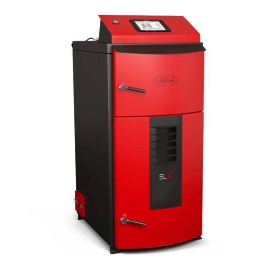
THE WOOD GASIFYING BOILER
ATTACK® SLX
PROFI / LAMBDA TOUCH
INSTRUCTIONS FOR USE
W W W . A T T A C K . S K
Table of
Contents
Previous
Page
Next
Page
1
2
3
4
5
Advertisement
Table of Contents
Need help?
Do you have a question about the SLX20 and is the answer not in the manual?
Ask a question
Questions and answers
Related Manuals for ATTACK SLX20
Boiler ATTACK STANDARD User Manual
Wood gasifying boiler (24 pages)
Boiler ATTACK SLX30 Instructions For Use Manual
Profi / lambda touch (76 pages)
Boiler ATTACK SLX25 Instructions For Use Manual
Profi / lambda touch (76 pages)
Boiler ATTACK ATTACK DPX COMBI PELLET Series Instructions For Use Manual
(100 pages)
Boiler ATTACK ATTACK DP STANDARD Instructions For Use Manual
Wood gasifying boiler (40 pages)
Boiler ATTACK DPX15 Instructions For Use Manual
Wood gasifying boiler (51 pages)
Boiler ATTACK EKO Instructions For Use Manual
Cast iron floor standing, capacity of 9, 12, 15, 20, 25, 30, 35, 40, 45, 49,9 kw (24 pages)
Boiler ATTACK FD20 Instructions For Use Manual
Fd solid fire (44 pages)
Boiler ATTACK WOOD&PELLET 25 Instructions For Use Manual
(100 pages)
Boiler ATTACK AWP 25 Instructions For Use Manual
Combined boiler (60 pages)
Boiler ATTACK DP25 Technical Manual
Wood gasifying boiler (24 pages)
Boiler ATTACK DPX15 Instructions For Use Manual
Dpx wood gasifying boiler standard / profi / lambda (60 pages)
Boiler ATTACK KZT Instructions For Use Manual
Gas condensing boiler (36 pages)
Boiler ATTACK EKO Instructions For Use Manual
Cast iron floor standing gas boiler (28 pages)
Boiler ATTACK PELLET Series Instructions For Use Manual
Voiler for combustion of wooden pellets (74 pages)
Boiler ATTACK PELH30A Instructions For Use Manual
Pellet burner automatic 8–30 kw (32 pages)
This manual is also suitable for:
Slx30
Slx25
Slx35
Slx40
Slx45
Slx50
...
Show all
Slx55
Table of Contents
Print
Rename the bookmark
Delete bookmark?
Delete from my manuals?
Login
Sign In
OR
Sign in with Facebook
Sign in with Google
Upload manual
Upload from disk
Upload from URL


Need help?
Do you have a question about the SLX20 and is the answer not in the manual?
Questions and answers