Table of Contents
Advertisement
Quick Links
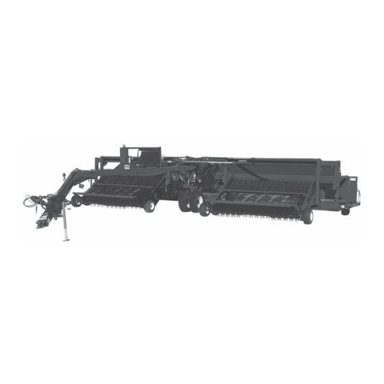
TWIN MERGER
WARNING
UNSAFE OPERATION OR MAINTENANCE OF THIS EQUIPMENT CAN RESULT IN
SERIOUS INJURY OR DEATH
OPERATOR'S MANUAL
H&S MANUFACTURING CO.,INC.
P.O. BOX 768 (715) 387-3414 FAX (715) 384-5463
READ AND UNDERSTAND THIS MANUAL
BEFORE OPERATING THIS EQUIPMENT
AND
PARTS LIST
Manufactured By
MARSHFIELD, WISCONSIN 54449
HSMFG20208
Advertisement
Table of Contents

Related Manuals for H&S TWIN MERGER


Summary of Contents for H&S TWIN MERGER
- Page 1 TWIN MERGER READ AND UNDERSTAND THIS MANUAL WARNING BEFORE OPERATING THIS EQUIPMENT UNSAFE OPERATION OR MAINTENANCE OF THIS EQUIPMENT CAN RESULT IN SERIOUS INJURY OR DEATH OPERATOR’S MANUAL PARTS LIST HSMFG20208 Manufactured By H&S MANUFACTURING CO.,INC. P.O. BOX 768 (715) 387-3414 FAX (715) 384-5463...
-
Page 2: Table Of Contents
Figure 10 - 9’ & 12’ Twin Merger Main Frame Hydraulics.......40-41... -
Page 3: Warranty & Warranty Registration
WARRANTY Mr. Owner: Before Operating-Read and Understand Operating and Safety Instructions. H&S Manufacturing Co., Inc. truly believes you have made a wise choice and a sound and lasting investment. Many years of development have made available these quality machines to assure you the performance and reliability you need. - Page 4 IMPORTANT! Tear on dotted line, provide the information requested on the card. The H&S Warranty is valid “only” after this card is received and recorded at H&S Mfg. Co. Mail at once. No postage is required in the U.S.A.
-
Page 5: Dealer Pre-Delivery & Delivery Checklist
AFTER COMPLETION, DEALER SHOULD REMOVE AND RETAIN FOR RECORDS H&S DEALER PRE-DELIVERY CHECK LIST After the Windrow Merger has been completely set-up, check to be certain it is in correct operating order before delivering to the customer. The following is a list of points to inspect. Check off each item as you have made the proper adjustments and found the item operating satisfactorily. -
Page 7: Be Alert Symbol
YOUR SAFETY ALERT! IS INVOLVED. THIS SYMBOL IS USED THROUGHOUT THIS BOOK WHENEVER YOUR PERSONAL SAFETY IS INVOLVED. TAKE TIME TO BE CAREFUL. REMEMBER: THE CAREFUL OPERATOR IS THE BEST OPERATOR. MOST ACCIDENTS ARE CAUSED BY HUMAN ERROR. CERTAIN PRECAUTIONS MUST BE OBSERVED TO PREVENT THE POSSIBILITY OF INJURY OR DAMAGE. -
Page 8: Explanation Of Safety Signs
RECOGNIZE SAFETY INFORMATION This is the safety-alert symbol. When you see this symbol on your machine or in this manual, be alert to the potential for personal injury. Follow recommended precautions and safe operating practices. UNDERSTAND SIGNAL WORDS A signal word- DANGER, WARNING, or CAUTION - is used with the safety-alert symbol. -
Page 10: Warning - Owner Must Read And Understand
TRACTORS This operators manual uses the term “Tractor” when identifying the the power source. W A R N I N G TO PREVENT SERIOUS INJURY OR DEATH BEFORE YOU ATTEMPT TO OPERATE THIS EQUIPMENT, READ AND STUDY THE FOLLOWING INFORMATION. IN ADDITION, MAKE SURE THAT EVERY INDIVIDUAL WHO OPERATES OR WORKS WITH THIS EQUIPMENT, WHETHER FAMILY MEMBER OR EMPLOYEE, IS FAMILIAR WITH THESE SAFTEY PRECAUTIONS. -
Page 12: Tractor Set-Up, Pre-Operation
There are a few things that can be done with the tractor set up to ensure the smooth efficient operation of the Twin merger. The drawbar should be set up at least 17 inches off the ground. This may require the drawbar to be “flipped”. - Page 13 PRE-OPERATION (Continued) Slide pump on receiver and secure with pin (E) provided and install safety-locking device. Slide spring loaded locking collar (F) on PTO yoke rearward, and slide yoke onto the tractor PTO shaft. Release spring loaded collar. Be sure the pins fall into the grove of the tractor PTO shaft and collar snaps forward into position.
-
Page 14: Hydraulic Drive Attachment
PRE-OPERATION (Continued) Plug the joy stick control box cord into the main wiring harness on pole (9’ head). Attach control box to a convenient place on the tractor. The tractor hydraulic circuit must now be locked in the open position to provide oil flow to the electric valve on merger. -
Page 15: Open/Closed Center Valve Conversion
OPEN/CLOSED CENTER SYSTEM Fig. 1 VALVE CONVERSION (9’ HEAD) The valve is supplied in a closed center configuration suitable for use in circuits utilizing pressure compensated pumps. For use in gear pumps (open center) circuits, a conversion is required. The valve outlet section has a “T” port, as shown in Fig. -
Page 16: Adjustments
Transport speed should not exceed 20 M.P.H. FRAME GAUGE WHEELS There are two frame gauge wheels used on each Twin Merger. Their sole purpose is to keep the frame from contacting the ground in uneven terrain. The picture to the right shows the frame gauge wheels in the working position. - Page 17 ADJUSTMENTS (Continued) PICKUP ADJUSTMENT Pickup belts may be adjusted by tightening the take up bolt (B) located on both ends of the pickup. The flange bearing bracket bolts (C) must be loosened before adjustment, and tightened after the desired belt tension is attained.
-
Page 18: Wiring Diagram - Joystick Plug
ADJUSTMENTS (Continued) CONVEYOR ADJUSTMENTS The cross conveyor belt tension can be adjusted by tightening the take up bolts (G) located on the two rollers located at the center of the machine. Proper tension may be achieved by compressing the springs to 3-1/4”. OPTIONAL ACCELERATOR ADJUSTMENTS Adjust cam (H) evenly on both sides of the accelerator to tighten chain and square accelerator... -
Page 19: Lubrication
LUBRICATION There are 42 grease fittings on your base merger. There are two zerks on the optional accelerator. If these are lubricated properly and often enough, it will prolong the life of the merger. Grease daily during normal use and before and after storage and after power washing. Use a good grade of high quality grease. Make sure grease comes out around the shaft on the sleeve type bearings. -
Page 20: Decal Location & Identification
DO NOT REMOVE ANY OF THESE DECALS. IF DECALS ARE LOST, DAMAGED, OR IF WINDROW MERGER IS REPAINTED, REPLACE DECALS. REMEMBER: DECALS ARE FOR YOUR PROTECTION AND SAFETY. Listed below are the decals on your Twin Merger. These decals may be ordered individually by part number or by ordering a complete set. ITEM PART NO. - Page 21 DECAL LOCATION (Continued) -19-...
-
Page 22: Trouble Shooting
TROUBLE SHOOTING WARNING MAKE SURE THAT THE TRACTOR IS SHUT OFF AND THE MERGER CAN NOT MOVE BEFORE SERVICING THE TWIN WINDROW MERGER. MAINTENANCE AND REPAIR SERVICE WORK TO BE PERFORMED BY A QUALIFIED SERVICE PERSON ONLY. TROUBLE... POSSIBLE CAUSE... POSSIBLE REMEDY... -
Page 23: Ordering Parts - About Improvements
INSTRUCTIONS FOR ORDERING PARTS All service parts should be ordered through your authorized H & S dealer. They will be able to give you faster service if you will provide them with the following Model & Serial number is located on the front, right main frame near pole pivot of your unit. All reference to left or right apply to the machine as viewed from the rear. - Page 24 -22-...
- Page 25 FIGURE 1 H&S 9’ & 12’ TWIN MERGER MAIN FRAME ITEM PART NO. DESCRIPTION ITEM PART NO. DESCRIPTION DWM137 Cap Screw - Coupler SHM17 Frame Gauge Wheel Hub Hair Pin CAT5 Seal DWM27 Coupler CAT6 Inner Bearing DWM36 Anti-Wrap Guard...
- Page 26 FIGURE 2 -24-...
- Page 27 FIGURE 2 H&S 9’ & 12’ TWIN MERGER MAIN FRAME (Continued) ITEM PART NO. DESCRIPTION ITEM PART NO. DESCRIPTION DWM337 Pole DWM164 11Lx15 HD Front Tire 12N24 Wheel (Front & Rear) DWM33 Pole Pin DWM73 Bronze Washer 3” ID DWM163 11Lx15 Rear Tire 7/8”...
- Page 28 FIGURE 3 -26-...
- Page 29 FIGURE 3 H&S 9’ TWIN MERGER LEFT PICK-UP HEAD ITEM PART NO. DESCRIPTION ITEM PART NO. DESCRIPTION 1.** DWM333 Wind Guard DWM57 Spacer 32.** DWM368 Wind Guard Poly 2.** DWM2 Double Wind Guard 3.** DWM351 Poly Wind Guard BFR69A Hydraulic Cylinder...
- Page 30 FIGURE 4 -28-...
- Page 31 FIGURE 4 H&S 9’ TWIN MERGER RIGHT PICK-UP HEAD ITEM PART NO. DESCRIPTION ITEM PART NO. DESCRIPTION 1.** DWM333 Wind Guard DWM57 Spacer 2.** DWM2 Double Wind Guard 32.** DWM368 Wind Guard Poly 3.** DWM351 Poly Wind Guard BFR69A Hydraulic Cylinder...
- Page 32 FIGURE 5 -30-...
- Page 33 FIGURE 5 H&S 12’ TWIN MERGER LEFT PICK-UP HEAD ITEM PART NO. DESCRIPTION ITEM PART NO. DESCRIPTION SHM3** Wind Guard SHM12 Bearing Bracket LH SHM9** Double Wind Guard WM180 Side Panel Slot Plate SHM11 ** Poly Wind Guard SHM13 Bearing Bracket RH...
- Page 34 FIGURE 6 -32-...
- Page 35 FIGURE 6 H&S 12’ TWIN MERGER RIGHT PICK-UP HEAD ITEM PART NO. DESCRIPTION ITEM PART NO. DESCRIPTION SHM3** Wind Guard SHM13 Bearing Bracket RH SHM9** Double Wind Guard SHM8 Pick-up Lifter SHM11** Poly Wind Guard DWM57 Spacer SHM21 Front Idler Roller...
- Page 36 FIGURE 7 -34-...
- Page 37 FIGURE 7 H&S 9’ & 12’ TWIN MERGER POLE CIRCUIT HYDRAULICS ITEM PART NO. DESCRIPTION DWM205 1/2” Quick Male Couplers DWM85 Hydraulic Hose 1/4” x 66” 3/8”MP & 1/2” MP HE60 3/8” Pipe Coupler DWM63 Short Pole Pipe DWM154 Hydraulic Hose 1/4” x 24” 3/8”MP & 3/8”MP...
- Page 38 FIGURE 8 -36-...
- Page 39 FIGURE 8 H&S 9’ TWIN MERGER ELECTRIC HEAD HYDRAULICS ITEM PART NO. DESCRIPTION DWM205 1/2” Male Quick Coupler WM141 1/2” Nipple Nut DF18 1/2” Check Valve PB105 1/2” Coupler DWM85 Hydraulic Hose 1/4” x 66” 3/8”MP & 1/2”MP HE60 3/8” Pipe Coupler...
- Page 40 FIGURE 9 -38-...
- Page 41 FIGURE 9 H&S 12’ TWIN MERGER HEAD HYDRAULICS ITEM PART NO. DESCRIPTION DWM205 1/2” Male Quick Coupler 16SV351 3/8” Nipple Nut 16SV338 3/8” Ball Valve DWM92 Hydraulic Hose 1/4” x 30” 3/8”MP & 3/8”MP DWM85 Hydraulic Hose 1/4” x 66” 3/8”MP & 1/2”MP HE60 3/8”...
- Page 42 FIGURE 10 -40-...
- Page 43 FIGURE 10 H&S 9’ & 12’ TWIN MERGER MAIN FRAME HYDRAULICS ITEM PART NO. DESCRIPTION ITEM PART NO. DESCRIPTION DWM337 Pole Tank DWM100 Hyd. Hose 1/2”x77” 1/2”MP&1/2”MP DWM234 Motor Tubing A DWM103 Hyd.Hose1/2”X40”1/2”MPX1/2”MP DWM235 Motor Pipe DWM78 Oil Cooler DWM236...
- Page 44 FIGURE 11 FIGURE 11 H&S 9’ & 12’ TWIN MERGER PICK-UP HEAD 2” x 8” HYDRAULIC CYLINDER ITEM PART NO. DESCRIPTION 23N142A Clevis Cap 23N143A Rod Cap 23N144 Piston T134A BFR68 Cylinder Tube T186 Tie Rod 23N148 Piston Nut 23N149...
- Page 45 FIGURE 12 FIGURE 12 H&S 9’ & 12’ TWIN MERGER POLE 3-1/2” x 30” HYDRAULIC CYLINDER ITEM PART NO. DESCRIPTION DWM417 Clevis Cap DWM418 Rod Cap DWM419 Piston DWM420 DWM421 Cylinder Tube DWM422 Tie Rod DWM423 Piston Nut DWM424 Plug...
- Page 46 FIGURE 13 FIGURE 13 H&S 9’ TWIN MERGER HEAD SHUTTLE 2” x 38” HYDRAULIC CYLINDER ITEM PART NO. DESCRIPTION DWM202 Case Weldment DWM203 Rod Weldment BFR330 Head Gland BFR331 Piston BFR332 Jam Nut BFR333 Seal Kit BFR334 Snap Ring DWM152...
- Page 47 FIGURE 14 FIGURE 14 H&S 9’ & 12’ TWIN MERGER LOAD LEVELER 2-1/2” x 8” HYDRAULIC CYLINDER ITEM PART NO. DESCRIPTION T181A Clevis Cap T182A Rod Cap T183 Piston T184A T185 Cylinder Tube T186 Tie Rod 23N148 Piston Nut 23N149...
- Page 48 FIGURE 15 -46-...
- Page 49 FIGURE 15 H&S 9’ TWIN MERGER ELECTRIC/HYDRAULIC VALVE BREAKDOWN ITEM PART NO. DESCRIPTION DWM389 Close Center Plug DWM390 Solenoid Assembly DWM305 Din Connector DWM391 Seal Kit DWM392 Solenoid Block & Pin DWM393 Check Valve Repair Kit DWM388 Complete Valve NOTE: * (MEANS NOT SHOWN)
- Page 50 FIGURE 16 -48-...
- Page 51 FIGURE 16 H&S 9’ & 12’ TWIN MERGER ELECTRIC WIRING HARNESS ITEM 9’ HEAD 12’ HEAD DESCRIPTION DWM174 Joy Stick & Switch DWM139 Control Box Top DWM140 Control Box Bottom DWM175 Strained Relief (Cord Grip) DWM176 Cord DWM167 Complete Control Box...
- Page 52 FIGURE 17 FIGURE 17 H&S 9’ & 12’ TWIN MERGER PTO ASSEMBLY ITEM PART NO. DESCRIPTION S225 Spring Lock Repair Kit 37N73 Spring Lock Yoke Assembly #14121-1012 14NW KIT Cross & Bearing Kit (14R) DWM289 Yoke & Shaft 4N20 Nylon Repair Kit...
- Page 53 FIGURE 18 FIGURE 18 H&S 9’ & 12’ TWIN MERGER HITCH ASSEMBLY ITEM PART NO. DESCRIPTION ITEM PART NO. DESCRIPTION DWM336 Receiver Pump Mount DWM283 Pressure L-Flange DWM276 PTO Pump DWM284 O-Ring DWM302 Replacement Shaft Seal DWM285 Return L-Flange DWM277...
- Page 54 FIGURE 19 FIGURE 19 H&S 9’ & 12’ TWIN MERGER VALVE MOUNTING ITEM PART NO. DESCRIPTION DWM450 Conveyor Reverse Bracket DWM446 Valve (Complete) DWM104 Hydraulic Hose 1/2” X 19” - 1/2 MP X 1/2” MP DWM445 Wiring Harness DWM454 Union Adapter (6900-8-8)
- Page 55 FIGURE 20 FIGURE 20 H&S 9’ & 12’ TWIN MERGER CROSS CONVEYOR CONTROL BOX ITEM PART NO. DESCRIPTION DWM447 Control Box Top DWM448 Control Box Bottom DWM449 Control Box Mount HD174 Knob HD173 Panel Nut DWM455 Strain Relief DWM453 Switch (Hesitation)
- Page 56 FIGURE 21 -54-...
- Page 57 FIGURE 21 H&S 9’ & 12’ TWIN MERGER OPTIONAL ACCELERATOR ITEM PART NO. DESCRIPTION DWM207 Accelerator Shaft DWM212 Accelerator Plate DWM220 Rubber DWM211 Wrap Guard DWM208 Mounting Bracket (1) DWM221 1” Bearing DWM222 3/8” x 5-1/2” Carriage Bolt GR. 2...
- Page 58 FIGURE 22 FIGURE 22 H&S TWIN MERGER 9’ & 12’ CROP ROLLER 9’ 12’ ITEM PART # PART # DESCRIPTION WM357 WM346 Front Support WM347 “ Collar WM348 “ Left Arm WM349 “ Right Arm WM350 “ Right Bracket WM351 “...
- Page 59 SERVICE / MAINTENANCE RECORD DATE DESCRIPTION NOTES -57-...
- Page 60 SERVICE & PARTS NOTES:...
- Page 61 Warranty..........120 Days - Parts & Limited Labor. SPECIFICATIONS SUBJECT TO CHANGE WITHOUT NOTICE NOTE: Determine right or left side of Twin Merger by viewing it from the rear. If instructions or parts lists call for hardened bolts see page 9 to identify. H&S MANUFACTURING CO. INC.
- Page 62 H&S MFG. CO. products approved for the FEMA SEAL OF QUALITY...
Need help?
Do you have a question about the TWIN MERGER and is the answer not in the manual?
Questions and answers