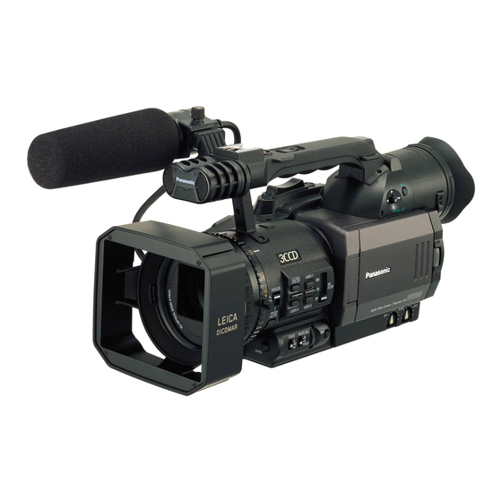
Panasonic AG-DVX100BP Service Manual
Hide thumbs Also See for AG-DVX100BP:
Table of Contents

Advertisement

Quick Links

.
Sec. 1
Service Information
Sec. 2
Disassembly Procedures
Sec. 3
Mechanical Adjustment
Sec. 4
Electrical Adjustment
Sec. 5
Block Diagrams
Sec. 6
Schematic Diagrams
Sec. 7
Circuit Board Diagrams
Sec. 8
Exploded Views &
Replacement Parts List
AG-DVX100BP/E/AN
AG-DVX102BEN
AG-DVC180BMC
© 2005 Matsushita Electric Industrial Co., Ltd. All rights reserved.
Unauthorized copying and distribution is a violation of law.
ORDER NO. BSD0510A25CE
D21
Camera-Recorder

Advertisement

Chapters

Table of Contents
loading

Summary of Contents for Panasonic AG-DVX100BP

  • Page 1 ORDER NO. BSD0510A25CE Sec. 1 Service Information Sec. 2 Disassembly Procedures Camera-Recorder Sec. 3 Mechanical Adjustment Sec. 4 Electrical Adjustment AG-DVX100BP/E/AN Sec. 5 Block Diagrams AG-DVX102BEN Sec. 6 Schematic Diagrams Sec. 7 Circuit Board Diagrams AG-DVC180BMC Sec. 8 Exploded Views &...
  • Page 2 Any attempt to service or repair the product or products dealt with in this service information by anyone else could result in serious injury or death. AG-DVX100BP - 2 -...
  • Page 3 - 3 -...
  • Page 4 AG-DVX100BE - 4 -...
  • Page 5 - 5 -...
  • Page 6 SAFETY PRECAUTIONS GENERAL GUIDELINES ELECTROSTATICALLY SENSITIVE (ES) DEVICES 1. When servicing, observe the original lead dress. If a Some semiconductor (solid state) devices can be damaged short circuit is found, replace all parts, which have been easily by static electricity. Such components commonly are over-heated or damaged by the short circuit.
  • Page 7 AG-DVX100BP - 7 -...
  • Page 8 AG-DVX100BE - 8 -...
  • Page 9 - 9 -...
  • Page 10 - 10 -...
  • Page 11 MHNK150/0123457F6S8P...
  • Page 12: Table Of Contents

    SERVICE INFORMATION AG-DVX100BP/E/AN,102BEN,DVC180BMC MODEL: CONTENTS 1. SERVICING FIXTURES AND TOOLS..................INF-1 1-1. Summary Table of Servicing Fixtures and Tools ..............INF-1 2. MAINTENANCE ..........................INF-4 2-1. Maintenance Schedule......................INF-4 2-2. Cleaning of Tape Transport Part..................INF-4 3. MANUAL TAPE EJECT (EMERGENCY EJECT) ...............INF-5 4. LITHIUM BATTERY ........................INF-6 4-1.
  • Page 13: Servicing Fixtures And Tools

    1. SERVICING FIXTURES AND TOOLS The following servicing tools are required for mechanical and electrical servicing and alignment. The items marked “NEW” in the following list are necessary for the AG-DVX100B/102B/DVC180B. Please refer to “Y” and “N” in column of table below, which tools required for servicing the NTSC and PAL model. Please refer to “Y”...
  • Page 14 VVS0026 VFM3010EDS VFM3000EDS VFK1308P DV Alignment Tape Measuring Board VFM3110EDS VVS0027 (Linearity) EVR Adjustment Software DV Alignment Tape (Color bar) VFK1481N LISTA Software DOWN LOAD VFK1763 VFK1982 VFK1309A VJA0941 EVR Connector Board DC Cable Connector Adapter Extension Cable VFK1809 VFK1317 VFK1164TAR43 VFK1164TCM01 72 mm Attachment Ring...
  • Page 15 To determine which servicing fixtures and tools are required for each adjustment, refer to the following table. ADJUSTMENT ITEM Parts No. NAME VFM3010EDS DV Alignment Tape (Color bar) 5-2. PG shifter adjustment (SEC.4) VFM3110EDS DV Alignment Tape (Color bar) VFM3000LS DV Alignment Tape (Linearity) 1-8.
  • Page 16: Maintenance

    2. MAINTENANCE Maintenance is done by periodically performing suitable maintenance servicing in order to maintain the best condition, so that the user can use the equipment safely. Video equipment with mounted mechanisms have parts which will wear, and their wear and deterioration cause troubles. Dust and dirt also can impair stable operation. For this reason it is important not to just perform repair at the time of trouble, but also to perform suitable maintenance at regular intervals.
  • Page 17: Manual Tape Eject (Emergency Eject)

    3. MANUAL TAPE EJECT (EMERGENCY EJECT) When the tape cannot be ejected by normal operation because of trouble in the electrical system or mechanical system, the tape can be removed from the unit manually by using the following method. NOTE: By below indicated method, the unit will not take up tape slack. Be careful when removing the tape from Cassette Holder.
  • Page 18: Lithium Battery

    4. LITHIUM BATTERY 4-1. Replacement Procedure There is a Lithium battery on the BACK CONNECT C.B.A. Unsolder the Lithium battery and then replace with the new one. Please refer to item “16. Removal of BACK CONNECT C.B.A.” in section 2(Disassembly Procedure) about how removal of BACK CONNECT C.B.A.. VTR C.B.A.
  • Page 19: Service Menu

    5. SERVICE MENU The SERVICE(CAMERA mode), DIAGNOSTIC(VCR mode) and ADJUST(VCR mode) menu can be displayed as follows. Press the button in order of “ADUB button” → “STOP button” → “MODE CHK button” → “MENU button”, SERVICE menu in CAMERA mode, DIAGNOSTIC and the ADJUST menu in VCR mode can be displayed in addition to a setup menus.
  • Page 20: Audio Filter

    5-1. SERVICE MENU (CAMERA mode) SERVICE MENU SERVICE MENU CYLINDER 10000H DEFFECT COMP AUDIO FILTER TAPE RUN 10000H VTR SUB MICON 1.001 THREADING 10000T VTR MAIN MICON 1.77-P-F Y LEVEL VTR EEPRPM 0.007 C LEVEL DIF INFO VTR EEPROM SUM D7EF CAM MICON 0.D0...
  • Page 21: Software Version Display

    5-1-2. Software Version Display. This unit have three pieces of microprocessor and two pieces of EEPROM. CAMERA board VTR board Microprocessor IC301 IC2001(VTR MAIN MICON) IC3001(VTR SUB MICON) EEPROM IC307 IC2006 VTR C.B.A.(Foil side) CAMERA C.B.A.(Foil side) IC3001 IC301 IC2006 IC2001 IC307 SERVICE MENU...
  • Page 22: Adjustment Item For Video Level

    5-1-4. Adjustment item for Video Level Y LEVEL Y level of VIDEO OUT and S-VIDEO OUTPUT signal can be adjusted on this item. The displayed value is the same as value for Luminance level adjustment in EVR adjustment. C LEVEL C level of VIDEO OUT and S-VIDEO OUTPUT signal can be adjusted on this item.
  • Page 23: Lcd/Evf Correction

    5-1-6. LCD/EVF Correction LCD OFFSET SERVICE MENU R signal output to LCD is corrected. 1: Correction level 1 LCD OFFSET 2: Correction level 2 EVF OFFSET PUSH MENU TO RETURN EVF OFFSET SERVICE MENU R signal output to EVF is corrected. LCD OFFSET 1: Correction level 1 EVF OFFSET...
  • Page 24: Diagnostic Menu (Vcr Mode)

    5-2. DIAGNOSTIC MENU (VCR mode) 5-2-1. How to display the Error Rate. This unit can be displayed Error Rate and it shows the playing condition of the VCR. In case of the error rate is displayed, BER DISPLAY and SAMPLE SPEED mode is select on DIAGNOSTIC menu. Select the item BER DISPLAY and press DIAGNOSTIC MENU SET(STILL) of OPERATION LEVER.
  • Page 25: Other Item

    5-2-2. Other item. DIAGNOSTIC MENU BER DISPLAY SAMPLE SPEED SLOW DIF INFO CYLINDER 10000H These items are displayed even by the CAMERA TAPE RUN 10000H SERVICE menu. (refer to item 5-1-3 and 5-1-5. ) THREADING 10000T PUSH MENU TO EXIT 5-3.
  • Page 26 5-3-1. Setting item for LISTA Measurement ATF GAIN The speed of the tape changes if this item set to “ON” for the ATF sensitivity confirmation. After selected “ON”, By pressing SET(STILL) of OPERATION LEVER, enter the adjustment mode and then exit the menu once.
  • Page 27: Eeprom

    6. EEPROM Several information are stored in EEPROM. Please refer to below explanation, which data stored in EEPROM. 6-1. Each Menu Data 6-1-1. Setting menu data VCR FUNCTIONS CAMERA MENU ▲ 1. PLAYBACK FUNCTIONS 1. SCENE FILE ▲ 2. RECORDING SETUP 2.
  • Page 28: Diagnostic Menu Data

    6-1-3. DIAGNOSTIC menu data Please refer to as follows. ITEM STORED IN BER DISPLAY SAMPLE SPEED DIF INFO CYLINDER VTR EEPROM TAPE RUN VTR EEPROM THREADING VTR EEPROM 6-1-4. ADJUST menu data Please refer to as follows. ITEM STORED IN ATF GAIN LINEARITY AUDIO FILTER...
  • Page 29: Camera Remote

    7. CAMERA REMOTE The operation of zoom operation and record start/stop can be remotely controlled by connecting a remote controller with ZOOM S/S remote jack. The operation of focus and iris operation can be remotely controlled by connecting a remote controller with FOCUS/IRIS remote jack.
  • Page 30: Focus/Iris Remote

    7-2. FOCUS/IRIS REMOTE Please refer to below indicated specification, When external remote is checked. Terminal (refer to figure A) Contents FOCUS control input IRIS control input IRIS(AUTO/MANU) switch input Equivalent circuit of FOCUS/IRIS REMOTE jack 4-pole / 3.5mm diameter Figure C 7-2-1.
  • Page 31: Iris Control Input

    7-2-2. IRIS control input When terminal D is open, the VCR becomes AUTO-IRIS mode. When terminal D connects with the GND, the VCR becomes MANUAL-IRIS mode. With the voltage to input to the C terminal, the iris is changes. As for the relation between the iris control voltage and the iris, it is as shown in the following.
  • Page 32: Caution When Installing Audio Control Knob

    8. CAUTION WHEN INSTALLING AUDIO CONTROL KNOB The AUDIO VR is weak against stress. So when the AUDIO Control Knob is removed from the AUDIO VR, it is very possible that AUDIO VR is broken. Please replace the AUDIO VR by a new one, when you have removed the AUDIO Control Knob from the AUDIO VR.
  • Page 33: Interconnection

    INTER CONNECTION DIAGRAM 4EMC MENU C.B.A. SPEAKER HANDLE HANDLE C.B.A. VF CASE L ZOOM SW UNIT UNIT UNIT UNIT MENU UNIT PANEL HANDLE ZOOM REC S/S REC CHECK SPEAKER BUTTON P653 P652 ZOOM OPERATION F REMOCON F TALLY BUTTON ZOOM SPEED SW R REMOCON LEVER EVF CON C.B.A.
  • Page 34: Circuit Board Layout

    10. CIRCUIT BOARD LAYOUT HANDLE C.B.A. TALLY FPC C.B.A. EVF CON C.B.A. ZOOM FPC C.B.A. POWER SW C.B.A. REAR JACK C.B.A. MODE SW C.B.A. BATTERY C.B.A. TOP CONNECT C.B.A. VTR C.B.A. DC IN C.B.A. SIDE JACK C.B.A. CAMERA C.B.A. MENU C.B.A. EXT MIC CH1 C.B.A.
  • Page 35 DISASSEMBLY PROCEDURES AJ-DVX100BP/E/AN,102BEN,DVC180BMC MODEL: CONTENTS Disassembly Flowchart ......................DIS-1 Note when inserting Flexible Cable..................DIS-2 Type of Screws.........................DIS-2 Removal of Top Panel Unit ......................DIS-3 Removal of VF CASE L Unit ....................DIS-3 Removal of Grip Unit........................DIS-4 Removal of Mechanism Unit and VTR C.B.A................DIS-6 Removal of Handle Unit ......................DIS-8 Removal of EVF Unit........................DIS-8 10.
  • Page 36: Disassembly Flowchart

      1. Disassembly Flowchart     4. Top Panel Unit 5. VF CASE L Unit 6. Grip Unit 7. Mechanism Unit and VTR C.B.A. 8. Handle Unit 9. EVF Unit   10. Side Case R S Unit 11. LCD Unit  ...
  • Page 37: Note When Inserting Flexible Cable

    2. Note when inserting Flexible 3. Type of Screws Cable As for this procedure, a screw is described by the alphabet. The specified screw, refer to the table below The flexible cables, have two sets of contacts on each about any type. When constructive, be careful not to cable, see the figure below.
  • Page 38: Removal Of Top Panel Unit

    4. Removal of Top Panel Unit 1. Unscrew the 2 screws (A) and disconnect a connector P610 on MENU C.B.A., then remove the VF CASE R UNIT. 2. Unscrew the 2 screws (B) and (C). NOTE: When unscrew the screw (C), set the LCD Panel to downward to protect damage on face of LCD.
  • Page 39: Removal Of Grip Unit

    6. Removal of Grip Unit SCREW (D) 1. Remove the VF CASE L Unit. 2. Unscrew the 5 screws (E) and remove the Bottom Cover. SCREW (E) BOTTOM COVER SCREW (D) SCREW (E) BLACK 3. Unscrew the screw (F) and open the cassette cover.
  • Page 40 < Note in installation > 1. Arm should be pressed in the direction of an SCREW (G) arrows as shown in figure A, and so that the position of the SW ARM is put into the state of figure B. Arm is pressed in this direction SW ARM SCREW (G)
  • Page 41: Removal Of Mechanism Unit And Vtr C.b.a

    7. Removal of Mechanism Unit and P2003 connection P2002 connection VTR C.B.A. 1. Remove the Grip Unit. 2. Disconnect 3 connectors P1501, P4001 and P3001 on VTR C.B.A. P1501 P2003 P4001 P3001 P2001 connection 3. Unscrew the 4 screws (H) and remove the Mechanism Unit (with VTR C.B.A.).
  • Page 42 NOTE: The connector P2201, 2202, 2203 and 2204 < Note in installation of VTR C.B.A.> are not lock types. Please pull out flexible After install SHILED CASE (A) to VTR C.B.A., install cable with a pick etc.. the SHILED CASE (B) to be puts projection part of SHIELD CASE (A) in the hole part of SHILED CASE NOTE: Even if VTR C.B.A.
  • Page 43: Removal Of Handle Unit

    8. Removal of Handle Unit 9. Removal of EVF Unit 1. Remove the VF CASE L Unit. 1. Remove the Handle Unit. 2. Unscrew the 4 screws (K) and disconnect the 2. Unscrew the 2 screws (L). connector P551 on TOP CONNECT C.B.A., then SCREW (L) remove the HANDLE UNIT.
  • Page 44: Removal Of Side Case R S Unit

    10. Removal of Side Case R S Unit SCREW (P) 1. Remove the Handle Unit. 2. Unscrew the 5 screws (N) and remove the Bottom Cover. SCREW (N) BOTTOM COVER 5. Disconnect a connector P4001 on VTR C.B.A.. P4001 SCREW (N) 3.
  • Page 45 NOTE: Do not damage the flexible cable in part shown in figure. And please confirm the wire is processed as shown in figure when install it. Lever Do not damage ND FILTER 7. Disconnect a connector P4670 on R-SIDE C.B.A. and remove the Side Case R S Unit.
  • Page 46: Removal Of Lcd Unit

    NOTE: Please match the hole of flexible cable and 11. Removal of LCD Unit projection of Side Case when you put the SHEET. 1. Remove the Side Case R S Unit. 2. Unscrew the screw (Q) and remove the SHIELD Match the hole and projection PLATE.
  • Page 47: Removal Of Camera C.b.a

    12. Removal of CAMERA C.B.A. LENS UNIT 1. Remove the Side Case R S Unit. 2. Disconnect connector P1004 and P1006 on CAMERA C.B.A.. 3. Unscrew the 4 screws (T) and remove the CAMERA C.B.A.. NOTE: When removal of the CAMERA C.B.A., the connector P1009 is disconnected (P1009 is connected between CAMERA and BACK CONNECT...
  • Page 48: Removal Of Back Case Unit

    6. Disconnect a connector P1501 on VTR C.B.A.. 15. Removal of Back Case Unit NOTE: When the connector P1501 is connected on VTR C.B.A., make the condition about wire 1. Remove the Side Case R S Unit. is processed as shown in figure. 2.
  • Page 49: Removal Of Back Connect C.b.a

    16. Removal of BACK CONNECT C.B.A. 1. Remove the Mechanism Unit (with VTR C.B.A.). 2. Remove the Side Case R S Unit. 3. Remove the CAMERA C.B.A.. 4. Remove the Back Case Unit. 5. Unscrew the 4 screws (Z) and remove the BACK CONNECT C.B.A..
  • Page 50 MECHANICAL ADJUSTMENT AG-DVX100BP/E/AN,102BEN,DVC180BMC MODEL: CONTENTS 1. MECHANICAL ADJUSTMENT AND CONFIRMATION ............MECH-1 1-1. Name of Tape Transportation..................MECH-1 1-2. Tape Path Adjustment Procedure................... MECH-1 1-3. Adjustment of S1 & T2 Post.................... MECH-2 1-4. Confirmation of EVR Tools ..................... MECH-2 1-5. Connection of LISTA Adjustment System ..............MECH-4 1-6.
  • Page 51: Mechanical Adjustment And Confirmation

    1. MECHANICAL ADJUSTMENT AND CONFIRMATION 1-1. Name of Tape Transportation Cylinder T1 Post S1 Post T2 Post Tension Post T3 Post Capstan Shaft S2 Post Pinch Roller LOADING condition 1-2. Tape Path Adjustment Procedure START LISTA Connection & Boot Up Confirmation of Tape Path Self-REC/PLAY ENV Confirmation LISTA Sensitivity Detection...
  • Page 52: Adjustment Of S1 & T2 Post

    1-3. Adjustment of S1 and T2 Post LISTA linearity and Envelope waveform are adjusted by S1 and T2 post. To adjust height of S1 and T2 post, below indicated operation is required. 1. Set to VCR mode in camera recorder and open the cassette cover. 2.
  • Page 53 2. Connect the 2 pcs. of 30 pin flat cables (VFK1317) between P101/P102 on the Measuring Board (VFK1308P), and 2 connectors on the EVR Connector Board (VFK1309A). Make sure that the contact surface of 2 pcs. of 30 pin Flat Cables are inner side and direction of the EVR Connector Board is as shown in Figure. Then connect the Connection Adapter (VFK1763).
  • Page 54: Connection Of Lista Adjustment System

    1-5. Connection of LISTA Adjustment System TAPE VFM3000LS (DV LISTA) M. EQ Personal Computer (A/D Board should be installed.) TOOL VFK1481N (LISTA Software), VFK1186 (LISTA Cable), VFK1300 (A/D Converter Board), VFK1308P (Measuring Board), VFK1409A (Measuring Board) ← NOTE 2 VFK1317 (30P flat cable): 2pcs, VFK1309A (EVR connector board) ← NOTE 1 VFK1763 (Connection Adapter), VFK1982 (Extension Cable), VJA0941 (DC cable): 2pcs.
  • Page 55 2. Connect a PC, the Measuring Board and the camera recorder as shown below. <CONNECTION> 1) In case of use VFK1409A Connect the EVR connector of DC6V to 9V camera recorder. It required PC W/AD board VFK1308P VFK1309A, VFK1763, VFK1982 and 2 pieces of VFK1317.
  • Page 56: Boot Up The Lista Software

    1-6. Boot up the LISTA Software Boot up the LISTA software on DOS mode. < How to Install and Boot Up > Make a directory like C: LISTA and copy all files in the VFK1481N(LISTA Software) to it on PC. Type “LISTA”...
  • Page 57: How To Enter The Alignment Tape Data

    1-7. How to Enter the Alignment Tape Data 1. Select the item “<4> Alignment Tape” on the LISTA main menu. 2. Select the item “<2> ENTRY” on the alignment menu. 3. After the screen displays the screen of <<Alignment Tape Data Entry>>, first input the Serial Number follow the printed number on the tape label.
  • Page 58: Lista Sensitivity Detection

    1-8. LISTA Sensitivity Detection In case of use VFK1409A F2 : ATF-ERR (VFK1409A), TP2 : TRG/HSW (VFK1409A), GND : GND (VFK1409A) In case of use VFK1409S F2 : ATF-ERR (VFK1409S), TP2 : TRG/HSW (VFK1810), GND : GND (VFK1409S) VTR MODE PLAY ADJ.
  • Page 59: Lista Linearity Adjustment

    1-9. LISTA Linearity Adjustment In case of use VFK1409A F2 : ATF-ERR (VFK1409A), TP2 : TRG/HSW (VFK1409A), GND : GND (VFK1409A) In case of use VFK1409S F2 : ATF-ERR (VFK1409S), TP2 : TRG/HSW (VFK1810), GND : GND (VFK1409S) ADJ. S1 and T1 Post Height VTR MODE PLAY ADJ.
  • Page 60 Adjust Linearity into this area. Figure 10 POINT : The left side of the waveform (entrance side) is adjusted by the height of S1 post and the right side of the waveform (exit side) is adjusted by the height of T2 post. When the post driver is removed from upper part of post, linearity waveform is changed.
  • Page 61: 1-10.Tape Path Confirmation

    1-10. Tape Pass Confirmation 1. Insert the Blank tape to the camera recorder. 2. Open the cassette cover follow the item “1-3. Adjustment of S1 and T2 Post” in this section. 3. Play back the Blank tape and confirm that the tape passes without curling at the upper and lower guides of the following posts in the Play modes as shown in below table.
  • Page 62: Mechanical Parts Replacement Procedure

    2. MECHANICAL PARTS REPLACEMENT PROCEDURE 2-1. Cleaning Roller Unit (Removal) 1. Remove the Mechanism Unit. 2. Unscrew the 2 screws (A) and (B), then remove the Cleaning Roller Unit. SCREW (B) Cleaning Roller Unit SCREW (A) Figure A (Installation) 1. Hook the portion (B) of Cleaning Roller Unit to portion (A) of Mechanism Chassis and install the Cleaning Roller Unit.
  • Page 63 ELECTRICAL ADJUSTMENT AG-DVX100BP/E/AN,102BEN,DVC180BMC MODEL: CONTENTS 1. REQUIRED TOOLS AND EQUIPMENT..................ELE-1 1-1. Required tools and equipment for each adjustment items ..........ELE-1 1-2. Required tools and PC EVR software ................ELE-2 2. CONNECTION..........................ELE-2 3. PC EVR SOFTWARE .........................ELE-5 3-1. Setup..........................ELE-5 3-2. Setting of communication ....................ELE-5 3-3.
  • Page 64: Required Tools And Equipment

    1. REQUIRED TOOLS AND EQUIPMENT 1-1. Required tools and equipment for each adjustment items. Below indicated tools are required to perform each adjustment in addition to tools in introduced in item1-2. Adjustment Item Required Tool Remark CAMERA Zoom SW center value Unnecessary Hall Amp (Auto) Unnecessary...
  • Page 65 1-2. Required tools and equipment for PC EVR software When performing the PC EVR electrical adjustment, the following tools are required. NAME Part Number Pcs. Remark PC EVR Software VVS0025 Download from the Global Service WEB site. Measuring Board VFK1308P EVR Connector Board VFK1309A Enable to use with VFK1309...
  • Page 66 1. Loosen the screw and remove the EVR cover. SCREW EVR COVER 2. Connect the 2 pcs. of 30 pin flat cables (VFK1317) between P101/P102 on the Measuring Board (VFK1308P), and 2 connectors on the EVR Connector Board (VFK1309A). Make sure that the contact surface of 2 pcs. of 30 pin Flat Cables are inner side and direction of the EVR Connector Board is as shown in Figures.
  • Page 67 4. Connect the Extension Cable (VFK1982) to EVR connector in Unit. Then make sure that the direction of the VFK1982 is correct as shown in Figure. When the VFK1982 is connected to EVR connector, be careful of the direction of connector on VFK1982. Please follow as shown in the figure.
  • Page 68: Pc Evr Software

    3. PC EVR SOFTWARE 3-1. Setup 1. Copy all files of the PC EVR software for AG-DVX100B series to the PC. 2. Supply power to the measuring board. 3. Supply power to the Camera-Recorder and turn power ON. 4. Start up the PC EVR software by double-clicking “dvx100b.exe”. The following screen will appear. 3-2.
  • Page 69: Save Eeprom Data Of Camera-Recorder To Pc

    3-3. Save EEPROM data of Camera-Recorder to PC 1. When communication between the PC and the Camera-Recorder has been succeeded, the following message appears. 2. Click “Cam” button to save Camera adjustment data and “Vcr” button to save VTR adjustment data. The screen to save data will appear.
  • Page 70: Main Menu

    3-4. Main menu 1. Click “Next” button after saving EEPROM data. 2. Main menu will appear as follows. 3-4-1. Explanation of main menu 11 12 1: Software name and version 7: Save and write EEPROM data 2: Save EEPROM data to PC 8: Memory editor (Usually not used) 3: Write EEPROM data from PC 9: CAMERA adjustment...
  • Page 71: Write Eeprom Data From Pc To Camera-Recorder

    3-5. Write EEPROM data from PC to Camera-Recorder You can return the Camera-Recorder to the condition before adjustment by writing EEPROM data, which has been saved before adjustment, to the Camera-Recorder. 1. Click the button for writing EEPROM data, which is indicated by “3” in the main menu on the previous page, or select “Write CAM all data to EEPROM(B)”...
  • Page 72: Adjustment Procedure (Camera Section)

    4. ADJUSTMENT PROCEDURE (CAMERA SECTION) Set the Camera-Recorder to CAMERA mode. Perform adjustments according to the order of main menu. 4-1. Zoom SW center value adjustment Double-click the adjustment item “Zoom SW center value” in the main menu. The instructions of adjustment will appear. Perform adjustment according to the instructions.
  • Page 73 Calculation of zoom SW center value 18. Calculate the center value with the minimum value of T side and the maximum value of W side as follows. <For example> Calculate center value FE (Upper) FF (Lower) Select minumum value Tele 01C3 (01C3 + 022C)÷2 = 01F7 Upper...
  • Page 74: Hall Amp Adjustment (Auto)

    4-2. Hall Amp adjustment (Auto) 1. Double-click the adjustment item “Hall Amp” in the main menu. The following screen will appear. 2. Click “Execute(E)” button. Automatic adjustment starts. 3. After adjustment has been completed, click “Close(C)” button to escape this menu. 4-3.
  • Page 75: Zoom Tracking Adjustment (Auto)

    4-5. Zoom tracking adjustment (Auto) 1. Set the 72mm Attachment Ring (VFK1809) to the front of Lens. 2. Set the 43mm attachment ring (VFK1164TAR43) to the Collimator (VFK1164TCM01). 3. Set the Collimator (VFK1164TCM01) with the 43mm attachment ring (VFK1164TAR43) to 72mm Attachment Ring (VFK1809).
  • Page 76: White Balance Adjustment (5100K) (Auto)

    4-6-2. White balance adjustment (5100K) (Auto) 1. Set the Color Conversion filters (LB120: VFK1347), (LBA2: VFK1884) and (LBB6: VFK1888) to the CC Filter Holder (VFK1345). 2. Set the one Step-down Ring (VFK1346) and two Step-up Rings (VFK1659, VFK1660) to the CC Filter Holder as shown in figure.
  • Page 77: White Balance Adjustment (4500K) (Auto)

    4-6-3. White balance adjustment (4500K) (Auto) < In case of NTSC model > 1. Set the Color Conversion filter (LB120: VFK1347) to the CC Filter Holder (VFK1345). < In case of PAL model > 1. Set the Color Conversion filters (LB80: VFK1342) and (CC C20: VFK1887) to the CC Filter Holder (VFK1345). <...
  • Page 78: White Balance Adjustment (3600K) (Auto)

    4-6-4. White balance adjustment (3600K) (Auto) < In case of NTSC model > 1. Set the Color Conversion filters (LB40: VFK1341) and (LBB2: VFK1885) to the CC Filter Holder (VFK1345). < In case of PAL model > 1. Set the Color Conversion filter (CC C10: VFK1886) to the CC Filter Holder (VFK1345). <...
  • Page 79: Ccd White Scratch Damage Revision Adjustment (Auto)

    < In case of PAL model > 6. Double-click the adjustment item “White balance (3600K) (PAL)” in the main menu. The following screen will appear. < Common procedures > 7. Click “Execute(E)” button. Automatic adjustment starts. 8. After adjustment has been completed, click “Close(C)” button to escape this menu. 4-7 CCD white scratch damage revision adjustment (Auto) 1.
  • Page 80: White Shading Adjustment (Auto)

    4-8 White shading adjustment (Auto) 1. Set the GAIN SW of Camera-Recorder to L (0dB). 2. Set the ATW to OFF. 3. Set the Iris to Auto. 4. Aim the Camera-Recorder at white paper under the Halogen lamp condition (3100K, 2000Lux). 5.
  • Page 81: Adjustment Procedure (Vtr Section)

    5. ADJUSTMENT PROCEDURE (VTR SECTION) Set the Camera-Recorder to VCR mode. Perform adjustments according to the order of main menu. 5-1. Sensitivity adjustment of tape sensors (Auto) NOTE: Do not insert the tape end/beg detect cassette to the Camera-Recorder. 1. Double-click the adjustment item “Sensitivity adj. of tape sensors” in the main menu. The following screen will appear.
  • Page 82: Luminance Level Adjustment

    5. After adjustment has been completed, confirm that the portion “T” is within specification as shown below. T = 126 ± 1 µsec 6. Click “Close(C)” button to escape this menu. 5-3. Luminance level adjustment 1. Connect the WFM (for NTSC) or the oscilloscope (for PAL) to the VIDEO OUT with 75ohm termination. 2.
  • Page 83: Chroma Level Adjustment

    5-4. Chroma level adjustment 1. Connect the WFM (for NTSC) or the oscilloscope (for PAL) to the VIDEO OUT with 75ohm termination. 2. Double-click the adjustment item “Chroma level” in the main menu. The following screen will appear. 3. Adjust chroma level by pressing the arrow keys of keyboard so that it is within specification. NTSC: V (Burst) = 40 IRE ±...
  • Page 84 BLOCK DIAGRAMS AG-DVX100B/P/E/AN,102BEN,DVC180BMC MODEL: CONTENTS OVERALL BLOCK DIAGRAM......................BLK-1 SENSOR/PROCESS (AFE / TG & DRIVE/PROCESS: CAMERA) BLOCK DIAGRAM ....BLK-2 LENS DRIVE (LENZ DRIVE / PROCESS: CAMERA) BLOCK DIAGRAM........BLK-3 VIDEO (VTR) BLOCK DIAGRAM ....................BLK-4 MONITOR (EVF: VTR / LCD: R SIDE) BLOCK DIAGRAM .............BLK-5 CONTROL (CONTROL / DRIVE: VTR) BLOCK DIAGRAM ............BLK-6...
  • Page 85 OVERALL BLOCK DIAGRAM LENS UNIT BACK CON C.B.A ZOOM FPC C.B.A EVF UNIT SIDE JACK C.B.A REAE JACK C.B.A GYRO_Y GYRO_X ZOOM TALLY FPC C.B.A SENSOR SENSOR AUDIO C.B.A BUTTON S-VHS VIDEO IN/OUT ZOOM IRIS FOCUS IN/OUT BATTERY IN/OUT IN/OUT FRONT CH1 &...
  • Page 86 SENSOR/PROCESS(AFE/TG & DRIVE/PROCESS: CAMERA) BLOCK DIAGRAM CCD FLEX.CARD P1004<3> SIG_R SIG_G SIG_B IC1<4>(CDS/PGA/AD)(R) IC105,120,125<5> IC106<5> X101<5> IC102<5> TIMING 31.5MHz CONTROL ADCLK DRIVER SLOAD IC104,123<5> SDATA SERIAL 48 SCLK IC111<5>(H.DRIVER) IC107,122<5> P1004<3> H1_R 15.75MHz H1_R H1_G SIG_R H.PULSE CCDIN H1_G IC103<5> H1_B DECODER H1_B...
  • Page 87 LENZ DRIVE (LENZ DRIVE / PROCESS: CAMERA) BLOCK DIAGRAM IC702<2>(LENS DRIVE) P1006<3> IC303<1>(CAMERA DSP) IC709<2> ZENC OUT E1-4 IRM+ IRM+ PLD_R F1-4 IRM- V IN SDATA LENS UNIT IRM- G1,2 HOUT- IRIS PLD_R(0-9) HOUT+ DRIVE R_DATA HIN- HIN+ PWMIRIS FMT+ FOCUS FMT- DRIVE...
  • Page 88 VIDEO (VTR) BLOCK DIAGRAM MAIN SIGNAL PATH IN REC MODE IC3001<1> (DUO) IC3501<5> (INPUT) MAIN SIGNAL PATH IN PLAYBACK MODE SIF_CS <3>from IC2001-M3 SBA_SIF_SDA U COM <3>from IC2001-L1 & L2 CLK27M M2-4 SBA_SIF_CLK <3>from IC2001-L3 N1-4, P1 P1009 P2002<10> IC3503<5> IC3504 SY_IO Q3503<5>...
  • Page 89 MONITOR(EVF: VTR / LCD: R_SIDE) BLOCK DIAGRAM EVF CON C.B.A IC3601<4> (EVF DRIVER) IC3001<1> IC3603<4> 2,4,6,8 3,5,7,9 11,13,15,17 12,14,16,18 EVF LCD BACK U18-21 PANEL LIGHT V19-21 ROUT BUFFER & GOUT <10>P2003 P651 P652 LYCIO(0-7) BOUT 40B 15 ON/OFF 14-16 18-22 STV2 26B 10 CKV2...
  • Page 90 CONTROL (CONTROL / DRIVE: VIDEO) BLOCK DIAGRAM IC2001<3>(CONTROL MICON) <10>P2010 DEW A3 ADM(0-15) ADDRESS QR2006<3> To/From IC3001<1> DATA H17, J20 TALLY_F_ LED L19, 20 M17,19,20 (HANDLE C.B.A) N18-21 P19,20 CASSETTE F TALLY LED TALLY_B_ LED R20,21 OPEN <10>P2003 P452 D401 SW9001<10>...
  • Page 91 SCHEMATIC DIAGRAMS AG-DVX100B/P/E/AN,102BEN,DVC180BMC MODEL: NOTE: BE SURE TO MAKE YOUR ORDERS OF REPLACEMENT PARTS ACCORDING TO PARTS LIST SECTION.
  • Page 92 CONTENTS INTERCONNECTION POWER SW INTERCONNECTION (1/1)........ SCM001 POWER SW ............. SCM041 REAR JACK DUO (1/11) ............SCM002 REAR JACK ............. SCM042 RIP&HRAMP (2/11) ........... SCM003 HANDLE CONTROL (3/11) ..........SCM004 HANDLE (1/3) ............ SCM043 EVF DRIVER (4/11) ........... SCM005 HANDLE (2/3) ............ SCM044 EXT INPUT (5/11) ..........
  • Page 93: Interconnection

    COMPONENT INTERCONNECTION 01/01 NAME CIRCUIT BOARD NO. DRAWING NO. (1/1) SCM001...
  • Page 94 COMPONENT VTR (DUO) 01/11 NAME CIRCUIT BOARD NO. DRAWING NO. KR 3A0324 (1/11) VEP03G82A/B SCM002...
  • Page 95 COMPONENT VTR (RIP&HRAMP) 02/11 NAME CIRCUIT BOARD NO. DRAWING NO. KR 3A0324 (2/11) VEP03G82A/B SCM003...
  • Page 96 COMPONENT VTR (CONTROL) 03/11 NAME CIRCUIT BOARD NO. DRAWING NO. KR 3A0324 (3/11) VEP03G82A/B SCM004...
  • Page 97 COMPONENT VTR (EVF DRIVER) 04/11 NAME CIRCUIT BOARD NO. DRAWING NO. KR 3A0324 (4/11) VEP03G82A/B SCM005...
  • Page 98 COMPONENT VTR (EXT INPUT) 05/11 NAME CIRCUIT BOARD NO. DRAWING NO. KR 3A0324 (5/11) VEP03G82A/B SCM006...
  • Page 99 COMPONENT VTR (DRIVER) 06/11 NAME CIRCUIT BOARD NO. DRAWING NO. KR 3A0324 (6/11) VEP03G82A/B SCM007...
  • Page 100 COMPONENT VTR (AV IO) 07/11 NAME CIRCUIT BOARD NO. DRAWING NO. KR 3A0324 (7/11) VEP03G82A/B SCM008...
  • Page 101 COMPONENT VTR (POWER 1) 08/11 NAME CIRCUIT BOARD NO. DRAWING NO. KR 3A0324 (8/11) VEP03G82A/B SCM009...
  • Page 102 COMPONENT VTR (POWER 2) 09/11 NAME  印の部品は安全上重要な部品です。交換するときは、 CIRCUIT BOARD NO. DRAWING NO. 警告 安全および性能維持のため必ず指定の部品をご使用ください。 KR 3A0324 (9/11) VEP03G82A/B Components identified with the mark have the special characteristics for safety. When replacing any of these components, use only the same type. SCM010...
  • Page 103 COMPONENT VTR (CN) 10/11 NAME CIRCUIT BOARD NO. DRAWING NO. KR 3A0324 (10/11) VEP03G82A/B SCM011...
  • Page 104 COMPONENT VTR (LCD BUFFER) 11/11 NAME CIRCUIT BOARD NO. DRAWING NO. KR 3A0324 (11/11) VEP03G82A/B SCM012...
  • Page 105 COMPONENT CAMERA (PROCESS) 01/05 NAME CIRCUIT BOARD NO. DRAWING NO. KR 3A0325 (1/5) VEP23638A/B SCM013...
  • Page 106 COMPONENT CAMERA (LENS DRIVE) 02/05 NAME CIRCUIT BOARD NO. DRAWING NO. KR 3A0325 (2/5) VEP23638A/B SCM014...
  • Page 107 COMPONENT CAMERA (SUB CN) 03/05 NAME CIRCUIT BOARD NO. DRAWING NO. KR 3A0325 (3/5) VEP23638A/B SCM015...
  • Page 108 COMPONENT CAMERA (AFE) 04/05 NAME CIRCUIT BOARD NO. DRAWING NO. KR 3A0325 (4/5) VEP23638A/B SCM016...
  • Page 109 COMPONENT CAMERA (TG&DRIVE) 05/05 NAME CIRCUIT BOARD NO. DRAWING NO. KR 3A0325 (5/5) VEP23638A/B SCM017...
  • Page 110 COMPONENT BACK CONNECT (CN) 01/02 NAME CIRCUIT BOARD NO. DRAWING NO. KR 3A0323 (1/2) VEP001K6A SCM018...
  • Page 111 COMPONENT BACK CONNECT (GYRO) 02/02 NAME CIRCUIT BOARD NO. DRAWING NO. KR 3A0323 (2/2) VEP001K6A SCM019...
  • Page 112: Top Connect

    COMPONENT TOP CONNECT 01/01 NAME CIRCUIT BOARD NO. DRAWING NO. KR 3A0324 (1/1) VEP001K7A SCM020...
  • Page 113: Cam Op1

    COMPONENT CAM OP1 01/01 NAME CIRCUIT BOARD NO. DRAWING NO. KR 6A0201 (1/1) VEP06G11A SCM021...
  • Page 114: Cam Op2

    COMPONENT CAM OP2 01/01 NAME CIRCUIT BOARD NO. DRAWING NO. KR 6A0202 (1/1) VEP06G12A SCM022...
  • Page 115: Cam Op3

    COMPONENT CAM OP3 01/01 NAME CIRCUIT BOARD NO. DRAWING NO. KR 6A0203 (1/1) VEP06G13A SCM023...
  • Page 116: Cam Op4

    COMPONENT CAM OP4 01/01 NAME CIRCUIT BOARD NO. DRAWING NO. KR 6A0204 (1/1) VEP06G14A SCM024...
  • Page 117 COMPONENT R SIDE (AUDIO) 01/05 NAME CIRCUIT BOARD NO. DRAWING NO. KR 6A0199 (1/5) VEP06G09A SCM025...
  • Page 118 COMPONENT R SIDE (KEY) 02/05 NAME CIRCUIT BOARD NO. DRAWING NO. KR 6A0199 (2/5) VEP06G09A SCM026...
  • Page 119: R Side (3/5)

    COMPONENT R SIDE 03/05 NAME CIRCUIT BOARD NO. DRAWING NO. KR 6A0199 (3/5) VEP06G09A SCM027...
  • Page 120 DVX100B 1.8V(REGD1R8V) HVX200 3.0V(REGD3V) COMPONENT R SIDE (LEV) 04/05 NAME CIRCUIT BOARD NO. DRAWING NO. KR 6A0199 (4/5) VEP06G09A SCM028...
  • Page 121 COMPONENT R SIDE (LCD PWR) 05/05 NAME CIRCUIT BOARD NO. DRAWING NO. KR 6A0199 (5/5) VEP06G09A SCM029...
  • Page 122: Lcd Lev (1/2)

    COMPONENT LCD LEV 01/02 NAME CIRCUIT BOARD NO. DRAWING NO. KR 8A0057 (1/2) VEP08346A SCM030...
  • Page 123 COMPONENT LCD LEV 02/02 NAME CIRCUIT BOARD NO. DRAWING NO. KR 8A0057 (2/2) VEP08346A SCM031...
  • Page 124: Menu

    COMPONENT MENU 01/01 NAME CIRCUIT BOARD NO. DRAWING NO. KR 6A0200 (1/1) VEP06G10A SCM032...
  • Page 125: Evf Connect

    COMPONENT EVF CONNECT 01/01 NAME CIRCUIT BOARD NO. DRAWING NO. KR 3A0339 (1/1) VEP29166A SCM033...
  • Page 126: Side Jack

    COMPONENT SIDE JACK 01/03 NAME CIRCUIT BOARD NO. DRAWING NO. KR 4A0151 (1/3) VEP04893A SCM034...
  • Page 127: Side Jack (2/3)

    COMPONENT SIDE JACK 02/03 NAME CIRCUIT BOARD NO. DRAWING NO. KR 4A0151 (2/3) VEP04893A SCM035...
  • Page 128: Side Jack (3/3)

    COMPONENT SIDE JACK 03/03 NAME CIRCUIT BOARD NO. DRAWING NO. KR 4A0151 (3/3) VEP04893A SCM036...
  • Page 129: Mic Ch1 (1/2)

    COMPONENT MIC CH1 01/02 NAME CIRCUIT BOARD NO. DRAWING NO. KR 4A0152 (1/2) VEP04894A SCM037...
  • Page 130: Mic Ch2

    COMPONENT MIC CH1 (CNT) 02/02 NAME CIRCUIT BOARD NO. DRAWING NO. KR 4A0152 (2/2) VEP04894A SCM038...
  • Page 131: Mic Ch2

    COMPONENT MIC CH2 01/01 NAME CIRCUIT BOARD NO. DRAWING NO. KR 4A0153 (1/1) VEP04895A SCM039...
  • Page 132: Mode Sw

    COMPONENT MODE SW 01/01 NAME CIRCUIT BOARD NO. DRAWING NO. KR 6A0198 (1/1) VEP06G08A SCM040...
  • Page 133: Power Sw

    COMPONENT POWER SW 01/01 NAME DRAWING NO. CIRCUIT BOARD NO. KR 6A0197 (1/1) VEP06G07A SCM041...
  • Page 134: Rear Jack

    COMPONENT REAR JACK 01/01 NAME CIRCUIT BOARD NO. DRAWING NO. KR 4A0150 (1/1) VEP04892A SCM042...
  • Page 135: Handle (1/3)

    COMPONENT HANDLE 01/03 NAME CIRCUIT BOARD NO. DRAWING NO. KR 6A0205 (1/3) VEP06G15A SCM043...
  • Page 136: Handle (3/3)

    COMPONENT HANDLE 02/03 NAME CIRCUIT BOARD NO. DRAWING NO. KR 6A0205 (2/3) VEP06G15A SCM044...
  • Page 137 COMPONENT HANDLE 03/03 NAME CIRCUIT BOARD NO. DRAWING NO. KR 6A0205 (3/3) VEP06G15A SCM045...
  • Page 138: Battery

    COMPONENT BATTERY 01/01 NAME  印の部品は安全上重要な部品です。交換するときは、 警告 安全および性能維持のため必ず指定の部品をご使用ください。 CIRCUIT BOARD NO. DRAWING NO. KR 1A0139 (1/1) Components identified with the mark have the special characteristics for safety. VEP01972A When replacing any of these components, use only the same type. SCM046...
  • Page 139: Dc In

    COMPONENT DC IN 01/01 NAME CIRCUIT BOARD NO. DRAWING NO. KR 1A0138 (1/1) VEP01971A SCM047...
  • Page 140: Zoom Fpc

    COMPONENT ZOOM FPC 01/01 NAME CIRCUIT BOARD NO. DRAWING NO. KR 6A0206 (1/1) VEP06G16A SCM048...
  • Page 141: Tally Fpc

    COMPONENT TALLY FPC 01/01 NAME CIRCUIT BOARD NO. DRAWING NO. KR 6A0207 (1/1) VEP66499A SCM049...
  • Page 142 CIRCUIT BOARD DIAGRAMS AG-DVX100B/P/E/AN,102BEN,DVC180BMC MODEL: NOTE: BE SURE TO MAKE YOUR ORDERS OF REPLACEMENT PARTS ACCORDING TO PARTS LIST SECTION. CONTENTS VTR C.B.A. (FOIL SIDE) ..........................CBA-1 VTR C.B.A. (COMPONENT SIDE)........................CBA-2 CAMERA C.B.A. (FOIL SIDE) .........................CBA-3 CAMERA C.B.A. (COMPONENT SIDE) ......................CBA-4...
  • Page 143 VIDEO C.B.A. (FOIL SIDE) FOIL SIDE IC1300 IC3305 IC5001 Q1083 Q3506 QR1805 TP2023 TP3003 IC1802 IC3306 IP1701 Q1101 Q3601 QR1806 TP2025 TP3004 IC2001 IC3313 P5001 Q1341 Q3602 QR1807 TP2026 TP3011 IC2006 IC3314 Q1011 Q1342 Q3607 QR1811 TP2029 TP3012 IC2015 IC3315 Q1021 Q1803 Q3610...
  • Page 144 VIDEO C.B.A. (COMPONENT SIDE) COMPONENT SIDE IC1001 IC3310 P2001 P3001 Q1813 Q3609 TP2032 TP9012 IC2002 IC3311 P2002 P4001 Q1814 QR1081 TP2034 X2001 IC2017 IC3312 P2003 Q1051 Q1815 QR1809 TP3503 IC2201 IC3501 P2010 Q1805 Q3503 QR3502 TP3504 IC3008 IC3503 P2201 Q1806 Q3504 QR3503 TP3505...
  • Page 145 CAMERA C.B.A. (FOIL SIDE) FOIL SIDE IC109 IC118 IC126 IC313 P1009 QR101 QR722 IC102 IC110 IC119 IC127 IC315 Q102 QR102 X101 IC103 IC111 IC120 IC128 IC316 Q103 QR103 X302 IC104 IC112 IC121 IC129 IC317 Q110 QR301 IC105 IC114 IC122 IC301 IC318 Q306 QR304...
  • Page 146 CAMERA C.B.A. (COMPONENT SIDE) COMPONENT SIDE IC304 IC704 IC713 IC720 Q708 QR708 TP102 IC308 IC707 IC717 P1002 Q709 QR709 TP103 IC125 IC701 IC709 IC718 P1004 QR303 TP100 IC303 IC702 IC711 IC719 P1006 QR705 TP101 CBA-4...
  • Page 147 EXPLODED VIEWS & REPLACEMENT PARTS LIST AG-DVX100BP/BE/BAN, AG-DVX102BEN, AG-DVC180BMC MODEL: CONTENTS FRAME & CASING PARTS ASSEMBLY (1) ...................MPL-1 FRAME & CASING PARTS ASSEMBLY (2) ...................MPL-3 HANDLE EVF PARTS ASSEMBLY ....................MPL-5 LCD PARTS ASSEMBLY.........................MPL-7 PACKING PARTS ASSEMBLY......................MPL-9 ELECTRICAL REPLACEMENT PARTS LIST .................EPL-1...
  • Page 148 FRAME & CASING PARTS ASSEMBLY (1) 64 65 MPL-1...
  • Page 149 SCREW VWJ10G6033L0 FLEXIBLE CABLE VSC5793 CF HEAT SINK VWJ1806 FLEXIBLE CABLE VGQ8096 COOLING SHEET C2 VEP23638A CAMERA C.B.A. 1 FOR AG-DVX100BP/AN VWJ20G6055L0 FLEXIBLE CABLE VEP23638B CAMERA C.B.A. 1 FOR AG-DVX100BE/EN/MC VGP6147 BACK CASE VEP06G09A R SIDE C.B.A. VMX0531 CLUTCH SPACER VEP06G11A CAM OP1 C.B.A.
  • Page 150: Frame & Casing Parts Assembly (1)

    FRAME & CASING PARTS ASSEMBLY (2) including MPL-3...
  • Page 151: Frame & Casing Parts Assembly (2)

    CLEANING ROLLER U VHD1546 SCREW VGQ8545 LENS HOOD VMP7605 LENS HOOD WINDOW VYK0Z96 LENS CAP U VXW0742 CAMERA LENS U 1 FOR AG-DVX100BP/AN VXW0743 CAMERA LENS U 1 FOR AG-DVX100BE/EN/MC VGQ8618 BOTTOM COVER VMP8473 CASSETTE LOCK ANGLE VGP6155 SIDE TOP PANEL VGU9255...
  • Page 152: Handle Evf Parts Assembly

    HANDLE EVF PARTS ASSEMBLY MPL-5...
  • Page 153 HANDLE EVF PARTS ASSEMBLY Ref.No. Part No. Part Name & DescriptionPcs Remarks Ref.No. Part No. Part Name & DescriptionPcs Remarks VKH0425 HANDLE VYF3062 REAR TALLY COVER U VJF1421 SHOE VMC1697 SPRING VGQ6887 MIC CASE (LOWER) VGQ6888 HANDLE FRONT COVER VGU9207 HANDLE S/S BUTTON VMG1479 HANDLE S/S BUTTON RUBBER...
  • Page 154 LCD PARTS ASSEMBLY MPL-7...
  • Page 155: Lcd Parts Assembly

    LCD PARTS ASSEMBLY Ref.No. Part No. Part Name & DescriptionPcs Remarks Ref.No. Part No. Part Name & DescriptionPcs Remarks VYK1R42 LCD U 1 FOR AG-DVX100BP/AN/E VYK1R60 LCD U 1 FOR AG-DVX102BEN VYK1R62 LCD U 1 FOR AG-DVC180BMC VGP6152 LCD CASE (BOTTOM)
  • Page 156 PACKING PARTS ASSEMBLY Components identified with the mark have the special characteristics for safety. When replacing any of these components, use only the same type. (E,EN) (E,EN,MC) (MC) MPL-9...
  • Page 157: Packing Parts Assembly

    PACKING PARTS ASSEMBLY Ref.No. Part No. Part Name & DescriptionPcs Remarks Ref.No. Part No. Part Name & DescriptionPcs Remarks VPG1F32 PACKING CASE 1 FOR AG-DVX100BP VPG1F33 PACKING CASE 1 FOR AG-DVX100BE VPG1F34 PACKING CASE 1 FOR AG-DVX102BEN VPG1F35 PACKING CASE...
  • Page 158: Electrical Replacement Parts List

    Ref.No. Part No. Part Name & DescriptionPcs Remarks C1023 ECJ0EB1H331K C.CAPACITOR CH 50V 330P ■ E1 VEP03G82A VTR C.B.A. 1 (RTL)FOR AG-DVX100BP/AN C1024 ECJ0EB1C223 C.CAPACITOR CH 16V 0.022P ■ E1 VEP03G82B VTR C.B.A. 1 (RTL)FOR AG-DVX100BE/EN/MC C1031 F1G1C473A004 C.CAPACITOR CH 16V 0.047U C1032 F1J0J475A008 C.CAPACITOR CH6.3V...
  • Page 159 Ref.No. Part No. Part Name & DescriptionPcs Remarks Ref.No. Part No. Part Name & DescriptionPcs Remarks C1830 F1L2A105A010 C.CAPACITOR CH100V C3221 F1J0J475A008 C.CAPACITOR CH6.3V 4.7U C1831 ECJ1VB1C105K C.CAPACITOR CH 16V C3229 ECJ0EB1A104K C.CAPACITOR CH 10V 0.1U C1832 F1L2A105A010 C.CAPACITOR CH100V C3261-63 ECJ0EB1A104K C.CAPACITOR CH 10V 0.1U C1833...
  • Page 160 Ref.No. Part No. Part Name & DescriptionPcs Remarks Ref.No. Part No. Part Name & DescriptionPcs Remarks C3621,22 ECJ0EB1A104K C.CAPACITOR CH 10V 0.1U IC3313 C1AB00001894 IC C3623 ECJ1VB1C105K C.CAPACITOR CH 16V IC3314 C0JBAR000394 IC C3624 ECJ0EB1A104K C.CAPACITOR CH 10V 0.1U IC3315 C0CBAAC00057 IC C3625 ECJ1VB1C105K C.CAPACITOR CH 16V...
  • Page 161 Ref.No. Part No. Part Name & DescriptionPcs Remarks Ref.No. Part No. Part Name & DescriptionPcs Remarks P2203,04 K1MN18BA0051 CONNECTOR R1035 ERJ2RHD272 M.RESISTOR CH 1/16W 2.7K P3001 K1MN45B00033 CONNECTOR R1036,37 ERJ2GE0R00 M.RESISTOR CH 1/16W P4001 K1KA08AA0266 CONNECTOR (MALE) R1041 ERJ2RHD102 M.RESISTOR CH 1/16W P5001 K1MN08AA0068 CONNECTOR R1042,43 ERJ2RKD820...
  • Page 162 Ref.No. Part No. Part Name & DescriptionPcs Remarks Ref.No. Part No. Part Name & DescriptionPcs Remarks R1832 ERJ2RHD273 M.RESISTOR CH 1/16W R2107 ERJ2RHD331X M.RESISTOR CH 1/16W R1833 ERJ2RHD563 M.RESISTOR CH 1/16W R2108 ERJ2RHD332 M.RESISTOR CH 1/16W 3.3K R1837 ERJ2GEJ473 M.RESISTOR CH 1/16W R2109 ERJ2GEJ222 M.RESISTOR CH 1/16W 2.2K...
  • Page 163 M.RESISTOR CH 1/16W R3509 ERJ6GEY0R00 M.RESISTOR CH 1/10W 1 D0YDR0000005 R3514 ERJ2RHD223 M.RESISTOR CH 1/16W ■ E2 VEP23638A CAMERA C.B.A. 1 (RTL)AG-DVX100BP/AN R3515 ERJ2RHD331X M.RESISTOR CH 1/16W ■ E2 VEP23638B CAMERA C.B.A. 1 (RTL)FOR AG-DVX100BE/EN/MC R3516 ERJ2GEJ103 M.RESISTOR CH 1/16W R3530-38 ERJ2GE0R00 M.RESISTOR CH 1/16W...
  • Page 164 Ref.No. Part No. Part Name & DescriptionPcs Remarks Ref.No. Part No. Part Name & DescriptionPcs Remarks ECJ0EB1A104K C.CAPACITOR CH 10V 0.1U C314 F3F1A106A046 T.CAPACITOR CH 10V ECUX1E471KBQ C.CAPACITOR CH 25V 470P C315 ECJ0EB1C153K C.CAPACITOR CH 16V 0.015U ECJ0EB1A104K C.CAPACITOR CH 10V 0.1U C319-22 ECJ0EB1A104K C.CAPACITOR CH 10V...
  • Page 165 Ref.No. Part No. Part Name & DescriptionPcs Remarks Ref.No. Part No. Part Name & DescriptionPcs Remarks C797 ECJ0EB1C103K C.CAPACITOR CH 16V 0.01U L701 G1C100KA0068 COIL 10UH C799 ECJ0EB1A104K C.CAPACITOR CH 10V 0.1U L702 G1C220KA0068 COIL 22UH C802 F3F1C1060002 T.CAPACITOR CH 16V L703,04 G1C100KA0068 COIL 10UH...
  • Page 166 Ref.No. Part No. Part Name & DescriptionPcs Remarks Ref.No. Part No. Part Name & DescriptionPcs Remarks R268 ERJ2GEJ333 M.RESISTOR CH 1/16W R597 ERJ2RHD102 M.RESISTOR CH 1/16W R269 ERJ2GEJ104 M.RESISTOR CH 1/16W 100K R598 ERJ2GEJ153 M.RESISTOR CH 1/16W R270 ERJ2GEJ333 M.RESISTOR CH 1/16W R600 ERJ2GEJ102 M.RESISTOR CH 1/16W...
  • Page 167 Ref.No. Part No. Part Name & DescriptionPcs Remarks Ref.No. Part No. Part Name & DescriptionPcs Remarks R900 ERJ2GEJ103 M.RESISTOR CH 1/16W C4641 ECUX1C106KBP C.CAPACITOR CH 16V R901,02 ERJ2GEJ105 M.RESISTOR CH 1/16W C4642,43 F1H1H104A783 C.CAPACITOR CH 50V 0.1U R903 ERAS39J5R6 M.RESISTOR C4644 F3H1V106A049 T.CAPACITOR CH 35V R904...
  • Page 168 Ref.No. Part No. Part Name & DescriptionPcs Remarks Ref.No. Part No. Part Name & DescriptionPcs Remarks SW4656 EVQQWS01W SWITCH SW4657 EVQQW101M SWITCH SW4658 EVQQWS01W SWITCH SW4659,60 EVQQW101M SWITCH SW4661 EVQQWS01W SWITCH SW4662,63 EVQQW101M SWITCH ■ E7 VEP06G14A CAM OP4 C.B.A. 1 (RTL) SW4670 K0C112B00009 SWITCH...
  • Page 169 Ref.No. Part No. Part Name & DescriptionPcs Remarks Ref.No. Part No. Part Name & DescriptionPcs Remarks Q4801 2SD182400L TRANSISTOR R453,54 ERJ3GEYJ181 M.RESISTOR CH 1/16W R457,58 ERJ3GEYJ223 M.RESISTOR CH 1/16W R459-62 ERJ3GEYG472 M.RESISTOR CH 1/16W 4.7K ■ E12 VEP001K6A BACK CONNECT C.B.A. 1 (RTL) R463,64 ERJ3GEYJ104...
  • Page 170 Ref.No. Part No. Part Name & DescriptionPcs Remarks Ref.No. Part No. Part Name & DescriptionPcs Remarks P551 K1MN24AA0018 CONNECTOR T4901-03 J0MAB0000196 FILTER P552,53 K1MN10AA0018 CONNECTOR P554 K1MR70B00004 CONNECTOR MISCELLANEOUS P555 K1MN22AA0018 CONNECTOR P556 K1KA02AA0104 CONNECTOR (MALE) VMP8472 BACK JACK ANGLE XQN2+B4FN SCREW Q551...
  • Page 171 Ref.No. Part No. Part Name & DescriptionPcs Remarks Ref.No. Part No. Part Name & DescriptionPcs Remarks R4474 ERJ3GEYG472 M.RESISTOR CH 1/16W 4.7K R4475,76 ERJ3GEY0R00 M.RESISTOR CH 1/16W ■ E20 VEP04894A MIC CH1 C.B.A. 1 (RTL) TH4401 D4CC11030012 THERMISTOR C4000,01 ECJ1VC1H471J C.CAPACITOR CH 50V 470P C4002 ECJ1VF1H103Z C.CAPACITOR CH 50V 0.01U...
  • Page 172 Ref.No. Part No. Part Name & DescriptionPcs Remarks Ref.No. Part No. Part Name & DescriptionPcs Remarks ■ E21 VEP06G08A MODE SW C.B.A. 1 (RTL) D151-56 MA3S781D0L DIODE D157 B3AAB0000037 DIODE D158 B3ABB0000086 LED D159 MA3S781D0L DIODE P152 K1MN16BA0059 CONNECTOR R154 ERJ3GEYJ181 M.RESISTOR CH 1/16W R155...

This manual is also suitable for:

Ag-dvx100beAg-dvx100banAg-dvc180bmcAg-dvx102ben

Table of Contents