Sign In
Upload
Manuals
Brands
Beckhoff Manuals
Control Unit
EP7211-0034
Beckhoff EP7211-0034 Manuals
Manuals and User Guides for Beckhoff EP7211-0034. We have
2
Beckhoff EP7211-0034 manuals available for free PDF download: Documentation, Application Example
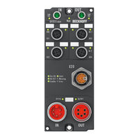
Beckhoff EP7211-0034 Documentation (147 pages)
Servomotor module with OCT
Brand:
Beckhoff
| Category:
Control Unit
| Size: 6 MB
Table of Contents
Table of Contents
3
1 Foreword
5
Notes on the Documentation
5
Safety Instructions
6
Documentation Issue Status
7
2 Product Overview
8
Ethercat Box - Introduction
8
Fig. 1 Ethercat Box Modules Within an Ethercat Network
8
Fig. 2 Ethercat Box with M8 Connections for Sensors/Actuators
9
Fig. 3 Ethercat Box with M12 Connections for Sensors/Actuators
9
EP7211-X034 - Introduction
10
Fig. 4 EP7211-9034
10
Technical Data
11
Scope of Supply
12
Technology
13
Fig. 5: Three Synchronous Motor Coils, each Offset by 120
13
Fig. 6 Limitation to the Rated Motor Current
14
3 Mounting and Cabling
15
Mounting
15
Dimensions
15
Fig. 7 Dimensions
15
Fixing
16
Functional Earth (FE)
16
Fig. 8 Functional Earth Via the Fastening Holes
16
Cabling
17
Fig. 9 Connector Overview
17
Power Supply
18
Fig. 10 7/8" Connector Pin Assignment
18
Fig. 11 Power Supply Status Leds
19
Fig. 12 Losses on the Supply Line
19
Ethercat
20
Fig. 13 Ethercat Connection
20
Fig. 14 M8 Socket Pin Assignment
20
Fig. 15 Ethercat Status Leds
21
Motor, Brake and Feedback System
22
Fig. 16 Itec Socket Pin Assignment
22
Fig. 17 Status Leds of the Motor Connection
23
Hardware Enable / Safe Torque off
24
Fig. 18 M12 Socket Pin Assignment
24
Fig. 19 Status Leds for HWE/STO
25
Fig. 20 Sample: Forwarded HWE/STO Signal
26
Touch Probe
27
Fig. 21 M12 Socket Pin Assignment
27
Fig. 22 Touch Probe Status Leds
27
4 Commissioning
29
Activate Motor Output Stage
29
Configuration in Twincat
29
Start-Up and Parameter Configuration
30
Integration into the NC Configuration
30
Fig. 23 Axis Detected
30
Fig. 24 Adding a New Task
31
Fig. 25 Adding a New Axis
31
Fig. 26 Selecting and Confirming the Axis Type
32
Fig. 27 Linking the Axis with the Box
32
Fig. 28 Selection of the Correct Box
32
Fig. 29 Automatic Linking of All Main Variables
33
Settings with the Drive Manager
34
Fig. 30 Selecting the Connected Voltage
34
Fig. 31 Automatic Scanning of the Connected Motor
35
Fig. 32 Selecting the Connected Motor
35
Fig. 33 List of Available Motors
36
Fig. 34 Confirmation of the Automatic NC Settings Parameters
36
Fig. 35 Adapting the Scaling
37
Fig. 36 Adapting Tn
38
Fig. 37 Adapting Kp
38
Settings in the Coe Register
39
Fig. 38 Importing the Motor XML File
39
Fig. 39 Selecting the Correct Motor XML File
40
Fig. 40 Coe Parameters of the Motor XML File
40
Fig. 41 Multi-Turn / Single-Turn Bits
41
NC Settings
42
Fig. 42 Definition of the Unit
42
Fig. 43 Adjusting the Reference Velocity
43
Fig. 44 Dead Time Compensation Parameter
43
Fig. 45 Setting the Encoder Mask
44
Fig. 46 Setting the Scaling Factor
45
Fig. 47 Output Scaling
45
Fig. 48 Lag Monitoring
46
Fig. 49 Enabling an Axis
47
Commissioning Without NC, Status Word/Control Word
48
Fig. 50 Reversing Sequence
48
Fig. 51 DS402 State Machine
49
Settings for the Automatic Configuration
51
Fig. 52 Flow Chart for the Automatic Configuration
52
Configure End Position Monitoring
53
Fig. 53 Pull-Down Menu for Activating End Position Monitoring
53
Homing
54
Fig. 54 Online Homing in the NC
54
Fig. 55 Configuration of the Mc_Home Block
55
Fig. 56 Extraction from the Functional Description for Mc_Home
55
Fig. 57 Selection of the Reference Modes in the NC
56
Fig. 58 Setting the Reference Velocity
56
Touch Probe
57
Fig. 59 Touch Probe Inputs
58
Fig. 60 Touch Probe Outputs
59
Drive Profiles
61
Operation Modes
62
Overview
62
Csv
63
Fig. 61 Selection of the Mode of Operation
63
Fig. 62 Selecting a Predefined PDO Assignment
64
Fig. 63 Set Enables
65
Fig. 64 Torque Specification
65
Cst
66
Fig. 65 Selection of the Mode of Operation
66
Fig. 66 Selecting a Predefined PDO Assignment
67
Fig. 67 Set Enabling
68
Fig. 68 Torque Specification
68
Cstca
69
Fig. 69 Selection of the Mode of Operation
69
Fig. 70 Selecting a Predefined PDO Assignment
70
Fig. 71 Set Enables
71
Fig. 72 Specification of Torque and Commutation Angle
71
Csp
72
Fig. 73 Selection of the Mode of Operation
72
Fig. 74 Selecting a Predefined PDO Assignment
73
Fig. 75 Set Enabling
74
Fig. 76 Position Specification
74
Fig. 77 Following Error Window
75
Fig. 78 Following Error Time out
75
Process Data MDP 742
76
Fig. 79 Process Data Tab SM2, EP7211 (Default)
76
Fig. 80 Process Data Tab SM3, EP7211 (Default)
77
Fig. 81 Process Data Tab - Predefined PDO Assignment
79
DS402 Process Data
80
Fig. 82 Process Data Tab SM2 (Default)
80
Fig. 83 Process Data Tab SM3 (Default)
81
Fig. 84 Process Data Tab - Predefined PDO Assignment
83
Object Description (MDP 742)
84
Restore Object
84
Configuration Data
84
Configuration Data (Vendor-Specific)
91
Command Object
91
Input Data
91
Output Data
93
Information / Diagnosis Data
95
Standard Objects
98
Object Description (DS402)
107
Configuration Data
108
Configuration Data (Vendor-Specific)
113
Command Object
113
Input/Output Data
114
Information / Diagnosis Data
119
Standard Objects
122
5 Appendix
129
General Operating Conditions
129
Firmware Update El/Es/Em/Elm/Epxxxx
130
Device Description ESI File/Xml
131
Fig. 85 Device Identifier Consisting of Name EL3204-0000 and Revision -0016
131
Fig. 86 Scan the Subordinate Field by Right-Clicking on the Ethercat Device
132
Fig. 87 Configuration Is Identical
132
Fig. 88 Change Dialog
132
Fig. 89 EEPROM Update
133
Fig. 90 Selecting the New ESI
133
Firmware Explanation
134
Updating Controller Firmware *.Efw
135
FPGA Firmware *.Rbf
136
Simultaneous Updating of Several Ethercat Devices
140
Ethercat Box- / Ethercat P Box - Accessories
141
Servo Technology - Accessories
141
General Note on the Introduction of the Beckhoff Identification Code (BIC)
142
Support and Service
144
List of Figures
145
Advertisement
Beckhoff EP7211-0034 Application Example (16 pages)
STO Function
Brand:
Beckhoff
| Category:
Servo Drives
| Size: 1 MB
Table of Contents
Table of Contents
3
1 Foreword
5
Notes on the Documentation
5
Documentation Issue Status
6
Purpose and Area of Application
6
Explanation of Terms
7
Operator's Obligation to Exercise Diligence
7
2 Safety Instructions
8
Delivery State
8
Operator's Obligation to Exercise Diligence
8
Description of Instructions
9
3 STO Function with EP7211-0034 (Category 3, PL D)
10
Parameters of the Safe Input and Output Terminals
11
Block Formation and Safety Loops
11
Safety Function 1
11
Calculation
12
PFHD / MTTFD / B10D - Values
12
Diagnostic Coverage DC
12
Calculation of Safety Function 1
12
4 Appendix
16
Support and Service
16
Advertisement
Related Products
Beckhoff EP7211 Series
Beckhoff EP7211-9034
Beckhoff EP7041 Series
Beckhoff EP7041-0002
Beckhoff EP7041-1002
Beckhoff EP7041-3102
Beckhoff EP7041-3002
Beckhoff EP7041-2002
Beckhoff EP 7 Series
Beckhoff EP1816-0008
Beckhoff Categories
Touch terminals
Industrial PC
Control Unit
Touch Panel
Industrial Equipment
More Beckhoff Manuals
Login
Sign In
OR
Sign in with Facebook
Sign in with Google
Upload manual
Upload from disk
Upload from URL