Table of Contents
Advertisement
Advertisement
Chapters
Table of Contents

Related Manuals for ETAS XETK-V2.0 Series


Summary of Contents for ETAS XETK-V2.0 Series
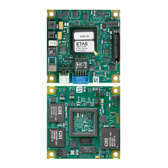
- Page 1 XETK-V2.0 Emulator Probe for MPC5600 and SPC5600 Family User’s Guide...
- Page 2 The data in this document may not be altered or amended without special noti- fication from ETAS GmbH. ETAS GmbH undertakes no further obligation in rela- tion to this document. The software described in it can only be used if the customer is in possession of a general license agreement or single license.
-
Page 3: Table Of Contents
ETAS Contents Contents About this Manual ..........7 Identification of Safety Notices . - Page 4 ETAS Hardware ........
- Page 5 CBAE200.2 Adapter Cable ......82 ETAS Module Interface Adapter Cable ......83 8.3.1...
- Page 6 10 ETAS Contact Addresses ........
-
Page 7: About This Manual
ETAS About this Manual About this Manual This chapter contains information about the following topics: • „Identification of Safety Notices“ on page 7 • „Presentation of Information“ on page 7 • „Scope of Supply“ on page 8 • „Additional Information“ on page 8... -
Page 8: Scope Of Supply
(see chapter "Order- ing Information"). Additional cables and adapters can be obtained separately from ETAS. A list of accessories and their order designation is available in this manual and at the ETAS Home Page. -
Page 9: Basic Safety Notices
• "Declarable Substances" on page 14 • "Use of Open Source Software" on page 14 General Safety Information Please observe the Product Safety Notices ("ETAS Safety Notice") and the follow- ing safety notices to avoid health issues or damage to the device. Note Carefully read the documentation (Product Safety Advice and this User's Guide) that belongs to the product prior to the startup. - Page 10 ETAS Basic Safety Notices • Use the product only according to the specifications in the corresponding User's Guide. With any deviating operation, the product safety is longer ensured. • Observe the regulations applicable at the operating location concerning electrical safety as well as the laws and regulations concerning work safety! •...
- Page 11 Cabling Use exclusively ETAS cables at the connections of the product! Adhere to the maximum permissible cable lengths! Observe the assignment of the cables to the connectors! Detailed information about cabling is located in the ETK User's Guides.
-
Page 12: Identifications On The Product
Order number of the product (example) SN: yyxxxxx Serial number (7-digit) XXXX/YY Product version ZZZZ Year of manufacture ETAS GmbH, Manufacturer's address PO Box 300220, 70442 Stuttgart, Germany Note For symbols and product information one or several adhesive labels can be used. -
Page 13: Taking The Product Back And Recycling
CE marking With the CE mark attached to the product or its packaging, ETAS confirms that the product corresponds to the applicable product-specific European Directives. The CE Declaration of Conformity for the product is available upon request. -
Page 14: Declarable Substances
Some products from ETAS GmbH (e.g. modules, boards, cables) use components with substances that are subject to declaration in accordance with the REACH regulation (EU) no.1907/2006. Detailed information is located in the ETAS download center in the customer information "REACH Declaration" (www.etas.com/Reach). This information is continuously being updated. -
Page 15: Introduction
XETK-V2.0C. The XETK-V2.0A/C combines a typical (X)ETK serial interface with a 32 bit SRAM and is based on the VertiCal interface concept from Freescale and ETAS. It can be used with the above microcontrollers packaged with a Vertical Base Board. -
Page 16: Features
The XETK-V2.0 supports the standard full duplex 100Base-T Ethernet interface and be connected directly or via ES51x/ES59x/ES600 modules to the PC. No addi- tional ETAS modules are required for the access to the ECU. The XETK-V2.0 can be used for rapid prototyping applications (bypass) as well as for measurement and calibration applications. - Page 17 ETAS Introduction – XETK-V2.0A/C provides additional Nexus (JTAG) compliant Samtec connector for external debug hardware – XETK-V2.0B hardware is prepared to be used simultaneously with a debugger, but an additional external arbitration circuit and debugger connection is required • ECU flashing via XETK –...
-
Page 18: Hardware Description
ETAS Hardware Description Hardware Description In this chapter, the function blocks of the XETK-V2.0 are explained in detail. Note The XETK-V2.0 can be ordered in three different functional and mechanical variants: XETK-V2.0A, XETK-V2.0B, and XETK-V2.0C. Within the manual the term "XETK-V2.0" describes features common to all variants. The term "XETK- V2.0A/C"... -
Page 19: Xetk-V2.0A/C Vertical Interface Concept
ETAS Hardware Description XETK-V2.0A/C XETK-V2.0B Watchdog Timer Disable ECU circuit back to Verti- ECU circuit back to XETK Cal Base Board optional ECU connector ball location Dimension (H/W/D) 12 / 60 / 60 mm 9 / 60 / 60 mm : ECU application specific: internal or external RAM... -
Page 20: Fig. 4-3 Vertical Base Board (Fitted With Pin Array/ Bga Adapter, Side View)
ETAS Hardware Description – VertiCal Shroud installed around the VertiCal connector to aid in align- ment during product installation Note For ECUs with BGA adapters VertiCal Base Boards with optional balls are required to use the DAI startup/ triggering and Watchdog Timer Disable fea- tures of the XETK-V2.0A/C. -
Page 21: Xetk-V2.0B Interface Concept
ETAS Hardware Description 4.1.3 XETK-V2.0B Interface Concept The XETK-V2.0B connects to the ECU in a similar manner to other serial (X)ETKs, using a cable with a standard debugging interface connector. The XETK-V2.0B is equipped with a 50 pin Nexus Samtec connector and connects to the ECU using an ETAHx ECU adapter cable. -
Page 22: Ecu Interface
ETAS Hardware Description If no additional measurement data memory is available, the XETK-V2.0 can alter- natively read the data to be measured directly from the microcontroller’s mem- ory. This process is Triggered Direct Measurement (TDM) with DISTAB13. The XETK-V2.0 can also receive the data to be measured via the Nexus Auxiliary interface using data trace windows and trace triggering. -
Page 23: Power Supply
ETAS Hardware Description For a complete list of the pins of the XETK-V2.0A/C ECU interface refer to section 7.11.1 on page 72 and to section 7.11.3 on page 79 for the XETK-V2.0B ECU Interface. In general the interface of each device consists of: •... -
Page 24: Xetk Ethernet Interface
PC. No additional ETAS module is required for the access to the ECU. The interface is a standard full duplex 100Base-TX Ethernet interface using the XCP protocol. The XETK Ethernet interface is integrated in the ETAS IP world with automatic IP management and supports the open automotive "Universal Mea- surement and Calibration"... -
Page 25: Status Leds
26). State Meaning XETK-V2.0 is supplied with power and active (i.e. the ECU is switched on or the ETAS calibration and development sys- tem is connected and ready to communicate with the XETK- V2.0) Green Power supply has dropped under 4.3V (XETK-V2.0A/C) or the selected standby threshold (XETK-V2.0B):... -
Page 26: Reset
This includes the 2 MByte of SRAM provided on the XETK-V2.0A or the 4 MByte provided on the XETK-V2.0C. As with parallel XETKs, serial XETKs have a system consisting of both a Reference and a Working Page (ETAS two page XETK concept). XETK-V2.0 - User’s Guide... -
Page 27: Page Switching
ETAS Hardware Description The Reference Page is located in the ECU flash and can not be modified by a simple write access. All changes to the Reference Page must be done via Flash programming. The INCA user can use ProF to invoke a customized flash pro- gramming algorithm. -
Page 28: Xetk-V2.0A/C Sram Characteristics & Data Retention
ETAS Hardware Description directing accesses to calibration data between either the Flash (Reference Page) or the RAM (Working Page) using microcontroller internal registers. The XETK- V2.0 has direct access to control these registers. To use Direct Register Access page switching the microcontroller software must initialize the necessary registers;... -
Page 29: Data Emulation Power Failures
ETAS Hardware Description 4.8.3 Data Emulation Power Failures The XETK-V2.0 has a circuit which recognizes and stores power failures. The XETK-V2.0 will notify the microcontroller software of the power failure using the DAI pins and additionally will prevent the user from switching to the working page until the PC software has downloaded a new Working Page data into the data emulation memory. -
Page 30: Xetk-V2.0B
ETAS Hardware Description The microcontroller is mounted directly on the VertiCal Base Board; therefore it is not possible to add additional series resistors between the microcontroller and XETK for TDO, /RDY, /EVTO, MCKO, MDOx, and /MSEOx. When the ECU design incorporates JTAG / Nexus connectors, additional circuitry is required to ensure these connectors and the signal routing do not influence the interface between the microcontroller and XETK. -
Page 31: Watchdog Timer Disable / Tool Detect Interface
ETAS Hardware Description The ECU part of the XETK-V2.0B Nexus (JTAG) interface is depicted in Fig. 4-13. For proper operation of the XETK-V2.0B it is mandatory to provide impedance matched series termination resistors on the ECU pcb for the signals TDO and / RDY (if available). -
Page 32: Fig. 4-14 Equivalent Circuitry Of The Xetk-V2.0A/C Wdt Interface Via Vertical (Bga)
ETAS Hardware Description Ball R19 (VertiCal 422/522) 3.3V Ball N16 (VertiCal 330) Pin 28 Ball K19 (VertiCal 214) Nexus Pin N22 XETK TOOL_IO2 Connector TOOL_IO2 TOOL_IO2 Watchdog System (Samtec) VertiCal 1= disable Controller VertiCal 0= enable Base Board Connector Balls µC... -
Page 33: Xetk-V2.0B
ETAS Hardware Description 4.10.2 XETK-V2.0B The watchdog disable control signal is available on the Samtec connector on signal TOOL_IO2 (pin 28). When the XETK-V2.0B is configured to use this signal (Configuration parameter "ECU Watchdog Control" set to "Disabled"), the signal TOOL_IO2 is set to logic high. -
Page 34: Xetk-V2.0A/C Dai Interface Via Qfp Vertical Base Boards
ETAS Hardware Description VCC_GPIO Ball N19 (VertiCal 422/522) Ball L16 (VertiCal 330) TOOL_IO0 Ball H19 (VertiCal 214) DAI1 TOOL_IO0 GPIO VCC_GPIO Ball P19 (VertiCal 422/522) Ball M16 (VertiCal 330) Ball J19 (VertiCal 214) TOOL_IO1 DAI2 TOOL_IO1 GPIO VertiCal VertiCal µC... -
Page 35: Xetk-V2.0B Dai Interface
ETAS Hardware Description VCC_GPIO TOOL_IO0 DAI1 VCC_GPIO TOOL_IO1 DAI2 VertiCal GPIO GPIO VertiCal Base XETK System Connector Board Controller µC VertiCal Base Board XETK-V2.0A/C (QFP) Fig. 4-17 Equivalent Circuitry of the XETK-V2.0A/C DAI Interface via VertiCal (QFP) To ensure proper operation of the startup protocol between ECU and XETK the QFP VertiCal Base Board contains circuitry to respect the following topics: •... -
Page 36: Phases Of The Startup Protocol
ETAS Hardware Description XETK-V2.0B XETK µC System Controller VCC_GPIO VCC_GPIO DAI1 GPIO DAI2 GPIO Fig. 4-18 Equivalent Circuitry of the XETK-V2.0B DAI Interface To ensure proper operation of the startup protocol between ECU and XETK the circuitry has to respect the following topics: •... -
Page 37: Triggering Of Measurement Data Acquisition
ETAS Hardware Description oÉëÉí í a^fN í a^fO í mÜ~ëÉ=N mÜ~ëÉ=O mÜ~ëÉ=P mÜ~ëÉ=Q mÜ~ëÉ=N mÜ~ëÉ=O mÜ~ëÉ=P mÜ~ëÉ=Q Fig. 4-19 Phases of the Startup Protocol (XETK connected) Successive phases of the startup protocol (XETK connected) 1. Reset phase: The ECU is in reset, the DAI ports are configured as inputs or tri-state. -
Page 38: Pinless Startup And Triggering
ETAS Hardware Description The required circuitry for the trigger lines DAI1 and DAI2 on the ECU is shown in Fig. 4-16 "Equivalent Circuitry of the XETK-V2.0A/C DAI Interface via VertiCal (BGA)",Fig. 4-17 "Equivalent Circuitry of the XETK-V2.0A/C DAI Interface via VertiCal (QFP)", and Fig. -
Page 39: Triggering Of Measurement Data Acquisition
ETAS Hardware Description pares the value to the expected value of 0x55555555. When the pattern matches, the XETK starts initialization and data acquisition (e.g. coldstart, check- sum, downloads, etc). 4.12.2 Triggering of Measurement Data Acquisition Initialization After the startup handshake and measurement is enabled, the XETK is waiting for triggers from the ECU software via the DTS_SEMAPHORE and /EVTO signal. -
Page 40: Xetk-V2.0A/C Microcontroller Ebi Voltage Supply
ETAS Hardware Description The trace trigger events to the XETK are synchronous to the microcontroller soft- ware. Variables assigned to a measurement raster using a trace trigger are acquired using the Nexus Auxiliary trace interface, not via JTAG. Note It is not possible to use the XETK-V2.0 configured with trace triggers and a debugger with program/data trace simultaneously. -
Page 41: Braindead Flashing
ETAS Hardware Description When using debug and trace tools with the XETK-V2.0A/C the devices must be powered on and powered off in the correct order. The power on sequence is as follows. First power on the debug and trace tool, next the XETK-V2.0A/C, and finally the ECU. -
Page 42: External Watchdog Disable
ETAS Hardware Description • Download flash programming driver into the internal RAM region of the controller that contains communication and flash routines • Set Program Counter to point to the beginning of the flash programming driver • Resume microcontroller code execution by issuing a go/resume command •... -
Page 43: Installation
ETAS Installation Installation In this chapter, the hardware installation of the XETK-V2.0 is described. CAUTION! The XETK can be damaged or destroyed! Some components of the interface board may be damaged or destroyed by electrostatic discharges. Please keep the board in its ... -
Page 44: Xetk-V2.0B
ETAS Installation 5.1.2 XETK-V2.0B bq^eN ubqhJsOKM_ b`r=`çååÉÅíçê Fig. 5-2 XETK-V2.0B Connection to the ECU with Socket/Adapter For mounting the XETK-V2.0B on the ECU accessories are required (see Fig. 5-2): • ETAH1 - A Mictor 38 receptacle mounted on the ECU printed circuit board. -
Page 45: Wiring
XETK Ethernet Interface The XETK Ethernet interface can be directly connected to the PC. No additional ETAS module is required for the access to the ECU. Note The XETK Ethernet interface is not compatible with the ETK interfaces in mod- ... -
Page 46: Power Supply
ETAS Installation 5.2.2 Power Supply The XETK-V2.0 needs a permanent power supply (refer chapter "Power Supply" on page 23). There are different versions to ensure it. Permanent Power Supply inside ECU available mçïÉê=pìééäó=`çååÉÅíçê mÉêã~åÉåí=pìééäó= m~Ç=Ñçê=mçïÉê=pìééäó `~ÄäÉ=bqs sÉÜáÅäÉ= Å~K táêáåÖ PS=s... -
Page 47: Fig. 5-6 Wiring - Isolated Power Supply Inside Ecu
ETAS Installation Isolated Power Supply inside ECU The XETK-V2.0 does not require a galvanically isolated power supply. For special applications ETAS offers the isolated power supply ETP2. mçïÉê=pìééäó=`çååÉÅíçê mÉêã~åÉåí=pìééäó= fëçä~íÉÇ=mçïÉê=pìééäó m~Ç=Ñçê=mçïÉê=pìééäó fåéìí `~ÄäÉ `~ÄäÉ=bqsO QIUsÁ=PSs NO=s `_jOMM sÉÜáÅäÉ= Å~K lìíéìí... -
Page 48: Xetk Configuration
ETAS XETK Configuration XETK Configuration The "XETK Configuration" chapter describes the XETK-V2.0 hardware configu- ration. Overview As already mentioned in previous chapters, some project-specific adjustments are necessary. Configuration data is stored permanently in a serial Flash. Generating a valid configuration data set is supported by the "(X)ETK Configura- tion Tool"... - Page 49 ETAS XETK Configuration Starting the "XCT Tool" help • Start the XCT Tool. The main window of the XCT tool opens. Contents. • Select in the menu bar ? The XCT Tool help window opens. (X)ETK • Choose Reference to User Interface Hardware Configuration Parameters.
-
Page 50: Technical Data
The “Technical Data” chapter contains a summary of all technical data, pin assignments and hints to system requirements for operating the XETK-V2.0. System Requirements 7.1.1 ETAS Hardware Compact Hardware: ES51x, ES592, ES593-D, ES595, ES600 (INCA) ES910 (INCA, INTECRIO) 7.1.2 Ethernet Interface of the PC A PC with a free Ethernet interface (1 GBit/s or 100 Mbit/s, Full Duplex) with an RJ-45 connection is required. -
Page 51: Environmental Conditions
ETAS Technical Data Microcontroller INCA ETK ASCET-RP INTECRIO Drivers and Tools MPC5676R_Rev1 V9.3.1 V6.2.1 V2.1.12 V6.1 V3.2 V9.3.1 V7.0.0 V3.2.1 MPC5777C_Rev1 V10.4 V7.1.4 V4.0.1 V6.1 V3.2 Data Acquisition via the Nexus Auxiliary trace interface is not possible with this microcontroller and the listed software versions. -
Page 52: Power Supply
ETAS Technical Data Power Supply 7.3.1 XETK-V2.0A/C Parameter Symbol Condition Max Unit Permanent power Vehicle usage Batt supply (car battery) Standby current = 12 V; STBY Batt ECU off; T = 20 °C Operating = 12 V; Batt Batt current ECU on;... -
Page 53: Configuration
ETAS Technical Data Configuration Item Characteristics Configuration Project-specific; stored in EEPROM for different microcontrollers and memory configurations Update Logic devices updated using HSP soft- ware XETK Ethernet Interface Item Characteristics Connection 100 Mbit/s Ethernet, Full Duplex PC Card 32 bit... -
Page 54: Ecu Interface Characteristics
ETAS Technical Data ECU Interface Characteristics 7.6.1 XETK-V2.0A/C Parameter Symbol Condition Max Unit ECU Power Supply ECU on: 3.3 V 2.75 2.90 3.05 V V_RESET Supervision ECU off: 3.3 V 2.55 2.70 2.85 V Voltage (3.3 V selected) ECU Power Supply ECU on: 5.0 V... -
Page 55: Test Characteristics
ETAS Technical Data Parameter Symbol Condition Max Unit ECU Standby ECU on: 2.5 V 2.15 2.30 2.45 V VSTBY Power Supply ECU off: 2.5 V 1.96 2.11 2.26 V Supervision Voltage (2.5 V selected) ECU Standby ECU on: 3.3 V via 2.75 2.90 3.05 V... -
Page 56: Electrical Characteristics
Electrical Characteristics 7.8.1 XETK-V2.0A/C ADDR[30] = 2.5 V; 2.37 2.62 0.75 -1/+1 V_CALBUS = -8 mA; = 8 mA = 3.3 V; 3.13 3.46 -1/+1 V_CALBUS = -8 mA; = 8 mA ADDR[29...16] = 2.5 V; 2.37 2.62 0.75 -1/+1 V_CALBUS = -8 mA;... - Page 57 ADDR[15, 13, 12] = 2.5 V; 2.37 0.75 -1/+1 V_CALBUS = -8 mA; = 8 mA = 3.3 V; 3.13 3.46 -1/+1 V_CALBUS = -8 mA; = 8 mA ADDR[14] = 2.5 V; 2.37 0.75 -1/+1 V_CALBUS = -8 mA; = 8 mA = 3.3 V;...
- Page 58 DATA[14] = 2.5 V; 2.37 0.75 -1/+1 V_CALBUS (CPU Type = = -8 mA; MPC5674F_Rev1 = 8 mA MPC5674F_Rev2 = 3.3 V; 3.13 3.46 -1/+1 V_CALBUS = -8 mA; = 8 mA DATA[14] = 2.5 V; 2.37 0.75 -1/+1 V_CALBUS (CPU Type = ...
- Page 59 /CS[3] (not selected) = 2.5 V; 0.75 -1/+1 V_CALBUS = 3.3 V; -1/+1 V_CALBUS /CS[3] (selected) = 2.5 V; 0.75 -1/+1 V_CALBUS = 3.3 V; -1/+1 V_CALBUS /CS[2] = 2.5 V; 2.37 0.75 -1/+1 V_CALBUS (CPU Type = = -8 mA;...
- Page 60 /CS[1..0] (selected) = 2.5 V; 0.75 -1/+1 V_CALBUS = 3.3 V; -1/+1 V_CALBUS /WE[3..2] = 2.5 V; 0.75 -1/+1 V_CALBUS = 3.3 V; -1/+1 V_CALBUS /WE[1..0] = 2.5 V; 0.75 -1/+1 V_CALBUS = 3.3 V; -1/+1 V_CALBUS CLKOUT = 2.5 V; 0.75 -1/+1 V_CALBUS...
- Page 61 = 2.5 V; 0.45 -15/+15 V_NEXUS = -1 mA; = 1 mA = 3.3 V; 0.45 -15/+15 V_NEXUS = -1 mA; = 1 mA TMS;TDI; = 2.5 V; 0.45 -15/+15 V_NEXUS /TRST (JCOMP) = -1 mA; = 1 mA = 3.3 V; 0.45 -15/+15 V_NEXUS...
- Page 62 /EVTI = 2.5 V; 0.55 1.75 -5/+5 V_NEXUS = -1 mA; = 1 mA = 3.3 V; 0.55 -5/+5 V_NEXUS = -1 mA; = 1 mA VertiCal plug, Samtec connector, and PCB not considered...
-
Page 63: Xetk-V2.0B
7.8.2 XETK-V2.0B = 2.5 V; 0.45 -15/+15 V_NEXUS = -1 mA; = 1 mA = 3.3 V; 0.45 -15/+15 V_NEXUS = -1 mA; = 1 mA TMS;TDI; = 2.5 V; 0.45 -15/+15 V_NEXUS /TRST (JCOMP) = -1 mA; = 1 mA = 3.3 V;... - Page 64 MDO[15..0]; /EVTO; = 2.5 V; -100/ V_NEXUS MCKO; +100 /MSEO[1..0] = 3.3 V; -100/ V_NEXUS +100 /EVTI = 2.5 V; 0.55 1.75 -100/ V_NEXUS = -1 mA; +100 = 1 mA = 3.3 V; 0.55 -100/ V_NEXUS = -1 mA; +100 = 1 mA /RSTOUT...
-
Page 65: Switching Characteristics
ETAS Technical Data Switching Characteristics The following diagrams show the timings the XETK-V2.0 can process. Note JTAG and Nexus timing parameters in this chapter refer to the ECU Interface of the XETK-V2.0 (XETK-V2.0A/C CON1 or XETK-V2.0B CON5). The wiring to the ECU (XETK-V2.0B ETAHx) and the ECU pcb routing or wiring must be addition-... -
Page 66: Nexus Timing Characteristics
ETAS Technical Data 7.9.2 Nexus Timing Characteristics MCKO MCKO /MSEO[1:0] MDO[16:0] Fig. 7-2 XETK-V2.0 Nexus Timing Diagram (valid up to 66 MHz) Parameter Min Unit MCKO SU_MDO[15:0] H_MDO[15:0] SU_/MSEO[1:0] H_/MSEO[1:0 7.9.3 XETK-V2.0A/C SRAM Read Timing CLKOUT /WR.RD ADDR[31:0] /CS[3:0] DATA[31:0] Fig. -
Page 67: Xetk-V2.0A/C Sram Write Timing
ETAS Technical Data Para. Description Unit /CS[x] (Chip Select) Hold Time /OE (Output Enable) to Data Valid /OE (Output Enable) to Data Invalid RD/WR (Read/Write) Setup Time RD/WR (Read/Write) Hold Time /OE (Output Enable) to Data Not Driven (High Z) -... -
Page 68: Mechanical Dimensions
ETAS Technical Data 7.10 Mechanical Dimensions The reference measure for all drawings is millimeter. 7.10.1 XETK-V2.0A/C XETK-V2.0A/C Dimensions - Top View Õ=c EQ=mäKF Fig. 7-5 XETK-V2.0A/C Dimensions - Top View Dimension Millimeters Inches 60.00 2.362 60.00 2.362 26.25 1.033 30.00 1.181... -
Page 69: Fig. 7-6 Xetk-V2.0A/C Dimensions - Side View
Board prior to insertion. Note Additional mechanical information (e.g. 3D IGES files) can be provided upon request. Refer to "ETAS Contact Addresses" on page 99 for the contact infor- mation of your local sales and technical support team. XETK-V2.0 - User’s Guide... -
Page 70: Xetk-V2.0B
ETAS Technical Data 7.10.2 XETK-V2.0B XETK-V2.0B Dimensions - Top View Õ=c EQ=mäKF Fig. 7-8 XETK-V2.0B Dimensions - Top View Dimension Millimeters Inches 60.00 2.362 60.00 2.362 26.25 1.033 30.00 1.181 0.295 3.45 0.136 XETK-V2.0 - User’s Guide... -
Page 71: Fig. 7-9 Xetk-V2.0B Dimensions - Side View
0.063 5.51 0.217 Note Additional mechanical information (e.g. 3D IGES files) can be provided upon request. Refer to "ETAS Contact Addresses" on page 99for the contact infor- mation of your local sales and technical support team. XETK-V2.0 - User’s Guide... -
Page 72: Pin Assignment
ETAS Technical Data 7.11 Pin Assignment 7.11.1 XETK-V2.0A/C VertiCal Connector Lbsqú jalú Loav pq_v s|`^ s|kb s|kb s|kb s|kb s|kb i_rp `ljm s|kb s|`^ s|`^ s|ob i_rp i_rp s|ob obpbq Lopq _llq `cdM `^k^ _llq `cdN `^k^ s|`^ s|`^ p`i^... - Page 73 ETAS Technical Data Pin(s) Name Description ADDR12 External Address / Data Bus ADDR13 ADDR14 ADDR15 ADDR16 ADDR17 ADDR18 ADDR19 ADDR20 ADDR21 ADDR22 ADDR23 ADDR24 ADDR25 ADDR26 ADDR27 ADDR28 ADDR29 ADDR30 /C_CS0 Chip Select /C_CS1 Chip Select /C_CS2 Chip Select /C_CS3...
- Page 74 ETAS Technical Data Pin(s) Name Description DATA0 External Address / Data Bus DATA1 DATA2 DATA3 DATA4 AA10 DATA5 AB10 DATA6 AA13 DATA7 AB13 DATA8 AA14 DATA9 AB14 DATA10 AA15 DATA11 AB15 DATA12 AA18 DATA13 AB18 DATA14 AA19 DATA15 MCKO Nexus Message Clock Out...
- Page 75 ETAS Technical Data Pin(s) Name Description JTAG Test Clock Input JTAG Test Mode Select Input JTAG Test Data Input JTAG Test Data Output JCOMP (/TRST) JTAG Compliance Input (JTAG Reset) /RESET External Reset Input/Sense /RSTOUT External Reset Output RSTCFG Reset Configuration Input...
- Page 76 ETAS Technical Data Pin(s) Name Description B2, B3, B5, B7, B9, Ground B11, B13, B15, B17, B19, B21, D21, F22, G1, G2, M1, M2, U1, U2, U21, V22, AA2, AA6, AA1, AA16, AA20, AB1, AB6, AB11, AB16, AB19, AB21 Address Latch Enable...
-
Page 77: Xetk-V2.0A/C Nexus (Jtag) Debugger Interface
ETAS Technical Data 7.11.2 XETK-V2.0A/C Nexus (JTAG) Debugger Interface Fig. 7-11 XETK-V2.0A/C Samtec Connector Pin(s) Name Description /MSEO0 V_NEXUS Nexus I/O voltage (sense only) /MSEO1 Ground MDO0 MDO1 Ground JCOMP =/TRST MDO2 /RDY MDO3 /EVTI Ground /EVTO MCKO /RESET MDO4... - Page 78 ETAS Technical Data Pin(s) Name Description TOOLIO_2 Watchdog disable and tool detect (TDET/WDT) Ground Ground MDO7 TOOLIO_0 Data Acquisition Interrupt 1 (DAI1) MDO8 TOOLIO_1 Data Acquisition Interrupt 2 (DAI2) Ground Ground MDO9 BREQ JTAG Arbitration: Bus Request MDO10 BGRANT JTAG Arbitration: Bus Grant...
-
Page 79: Xetk-V2.0B Ecu Interface
ETAS Technical Data 7.11.3 XETK-V2.0B ECU Interface Fig. 7-12 XETK-V2.0B Samtec Connector Pin(s) Name Comment /MSEO0 Nexus Message Start/End Out V_NEXUS Microcontroller Supply Voltage (Nexus) - Monitored by XETK /MSEO1 Nexus Message Start/End Out JTAG Test Clock Input Ground JTAG Test Mode Select Input... - Page 80 ETAS Technical Data Pin(s) Name Comment TOOLIO_2 External Watchdog Disable Ground Ground MDO7 Nexus Message Data Out TOOLIO_0 Data Acquisition Interrupt 1 (DAI1) MDO8 Nexus Message Data Out TOOLIO_1 Data Acquisition Interrupt 2 (DAI2) Ground Ground MDO9 Nexus Message Data Out...
-
Page 81: Cables And Accessories
ECU Adapter Cable Note The screws for mounting ECU adapter cables are not included in the cable delivery, they need to be ordered separately. For detailed information on mounting accessories contact ETAS technical support. 8.1.1 CBAM230.1 Adapter Cable Fig. 8-1 CBAM230.1 Adapter Cable... -
Page 82: Pc Interface Cable
ETAS Cables and Accessories PC Interface Cable 8.2.1 CBE200-3 Cable CBE200-x F 00K 104 37x 0000 Gigabit Ethernet Fig. 8-3 CBE200-3 Cable Product Length Order Number CBE200-3 F 00K 104 373 8.2.2 CBAE200.2 Adapter Cable Fig. 8-4 CBAE200.2 Adapter Cable Cable adapter to connect CBE230 cable to the PC over an RJ45 connector. -
Page 83: Etas Module Interface Adapter Cable
Cables and Accessories ETAS Module Interface Adapter Cable 8.3.1 CBE230.1 Cable Fig. 8-5 CBE230.1 Cable Gigabit Ethernet connection cable for ETAS devices. IP67 rated Lemo connectors on both sides. Gigabit Ethernet cable with power supply. Product Length Order Number CBE230.1-3 F 00K 105 757 CBE230.1-8... -
Page 84: Power Supply Cables
ETAS Cables and Accessories Power Supply Cables 8.4.1 Cable ETV Fig. 8-7 Cable ETV Millimeters Inches 190.00 7.480 8.4.2 Cable K70 Fig. 8-8 Cable K70 Millimeters Inches 2000 78.74 8.4.3 Cable KA50 Fig. 8-9 Cable KA50 Millimeters Inches 7.87 1.97... -
Page 85: Cable Cbm200
ETAS Cables and Accessories 8.4.4 Cable CBM200 Fig. 8-10 Cable CBM200 Millimeters Inches 3.94 XETK-V2.0 - User’s Guide... -
Page 86: Adapters
ETAS Cables and Accessories Adapters 8.5.1 ETAH1 ECU Interface Adapter for XETK-V2.0B p~ãíÉÅ jáÅíçê bq^eN Fig. 8-11 ETAH1 XETK-V2.0B - ECU Adapter Cable Adapter to connect XETK-V2.0B to an ECU equipped with a female Mictor 38 connector. The ETAH1 cable has a 50 Ohm impedance. The bend radius of the cable is 3.175 millimeters (.125 inches). -
Page 87: Fig. 8-13 Etah1 Samtec - Mictor (50Mc - 38Mc)
ETAS Cables and Accessories ETAH1 Pinout p~ãíÉÅ jáÅíçê bq^eN Fig. 8-13 ETAH1 Samtec - Mictor (50mc - 38mc) Samtec # Mictor # Comment /MSEO0 V_NEXUS /MSEO1 Ground Pins Ground MDO0 MDO1 Ground Pins Ground JCOMP (/TRST) MDO2 /RDY MDO3 /EVTI... - Page 88 ETAS Cables and Accessories Samtec # Mictor # Comment TOOLIO_0 (DAI1) MDO8 TOOLIO_1 (DAI2) Ground Pins Ground Ground Pins Ground MDO9 BREQ (Not Available) MDO10 BGRANT (Not Available) Ground Pins Ground Ground Pins Ground MDO11 MDO13 MDO12 MDO14 MDO15 VSTBY Note The specification of the Nexus (JTAG) interface bases on the "Nexus 5001...
-
Page 89: Etah2 Debugger Interface Adapter For Xetk-V2.0A/C
ETAS Cables and Accessories 8.5.2 ETAH2 Debugger Interface Adapter for XETK-V2.0A/C bq^eO aÉÄìÖÖÉê=`çååÉÅíáçå ubqhJsOKM^L`=`çååÉÅíáçå Fig. 8-14 ETAH2 XETK-V2.0A/C - Debugger Adapter Cable Adapter used to extend the debugger interface connector of the XETK-V2.0A/C. The mounting holes on the left side (XETK-V2.0A/C Connector side) align with the mounting holes on the XETK-V2.0A/C. -
Page 90: Fig. 8-16 Etah2 Samtec - Samtec (50Mc - 50Fc)
ETAS Cables and Accessories Dimension Millimeters Inches 60.00 2.362 25.40 1.000 3.75 0.148 3.50 0.138 45.71 1.800 101.60 4.000 ETAH2 Pinout máå=MN= _çííçã= `ç~ñ=`~ÄäÉë páÇÉ bq^eO aÉÄìÖÖÉê=`çååÉÅíáçå ubqhJsOKM^L`=`çååÉÅíáçå Fig. 8-16 ETAH2 Samtec - Samtec (50mc - 50fc) The signals are connected one to one, e.g. pin 1 of the left side is connected to pin 1 of the right side. -
Page 91: Etah5 Debugger Interface Adapter For Xetk-V2.0A/C
ETAS Cables and Accessories 8.5.3 ETAH5 Debugger Interface Adapter for XETK-V2.0A/C bq^eR aÉÄìÖÖÉê=`çååÉÅíáçå ubqhJsOKM^L`=`çååÉÅíáçå Fig. 8-17 ETAH5 XETK-V2.0A/C - Debugger Adapter Cable Adapter used to extend the debugger interface connector of the XETK-V2.0A/C. The mounting holes on the left side (XETK-V2.0A/C Connector side) align with the mounting holes on the XETK-V2.0A/C. -
Page 92: Etah4 Ecu Interface Adapter For Xetk-V2.0B
ETAS Cables and Accessories Dimension Millimeters Inches 60.00 2.362 13.00 0.512 3.75 0.148 3.50 0.138 45.71 1.800 80.00 3.150 ETAH5 Pinout bq^eR máå=MN=_çííçã=páÇÉ aÉÄìÖÖÉê=`çååÉÅíáçå ubqhJsOKM^L`=`çååÉÅíáçå Fig. 8-19 ETAH5 Samtec - Samtec (50mc - 50fc) The signals are connected one to one, e.g. pin 1 of the left side is connected to pin 1 of the right side. -
Page 93: Fig. 8-21 Etah4 Dimensions - Top View
ETAS Cables and Accessories Adapter to connect XETK-V2.0B to an ECU equipped with a female Samtec 50 connector. The ETAH4 cable has a 50 Ohm impedance. The bend radius of the cable is 3.175 millimeters (.125 inches). Product Order Number... -
Page 94: Ordering Information
ETAS Ordering Information Ordering Information XETK-V2.0 Type Order-No. Note XETK-V2.0A F-00K-106-941 XETK-V2.0 Emulator Probe with 2 MByte emulation memory for Freescale MPC5600 and ST SPC5600 microprocessors, ECU adaption via VertiCal Base Board XETK-V2.0B F-00K-107-036 XETK-V2.0 Emulator Probe without emulation memory for Freescale MPC5600 &... -
Page 95: Xetk-V2.0B - Ecu Adapter
ETAS Ordering Information XETK-V2.0B - ECU Adapter Type Order-No. Note ETAH1 F-00K-105-252 XETK ECU Adapter, Samtec - Mictor (50mc - 38mc), for con- necting an XETK-V2.0B to the ECU. Length: 21cm (0m21). ETAH4 F-00K-107-803 XETK ECU Adapter, Samtec - Samtec (50mc - 50mc), for con- necting an XETK-V2.0B to the... -
Page 96: Connector Xetk-V2.0B - Ecu Adapter Etah4
ETAS Ordering Information Connector XETK-V2.0B - ECU Adapter ETAH4 Connectors are available from Samtec. Type Order Number 50 pin Samtec Vertical Receptacle ASP-148422 XETK-V2.0 - User’s Guide... -
Page 97: Cables
ECU Adapter Cables Note The screws for mounting ECU adapter cables are not included in the cable delivery, they need to be ordered separately. For detailed information on mounting accessories contact ETAS technical support. Order Name Short Name Order Number XETK ECU Adapter Cable, 100 Mbit/s, CBAM230.1-... -
Page 98: Power Supply Cables
ETAS Ordering Information ES600 Interface Adapter Cable Order Name Short Name Order Number Ethernet Connection Adapter Cable 1 GBit/ CBAE330.2-0m5 F 00K 105 759 s to 100 MBit/s, Lemo 1B PHE - Lemo 1B FGF (10fc-8mc), 0m5 9.8.3 Power Supply Cables... -
Page 99: Etas Contact Addresses
Germany WWW: www.etas.com ETAS Subsidiaries and Technical Support For details of your local sales office as well as your local technical support team and product hotlines, take a look at the ETAS website: ETAS subsidiaries WWW: www.etas.com/en/contact.php ETAS technical support WWW: www.etas.com/en/hotlines.php... -
Page 100: Figures
ETAS Figures Figures Fig. 2-1 Adhesive Label (Example: Label for XETK-S14.0) ......... 12 Fig. 2-2 WEEE-Symbol ..................... 13 Fig. 3-1 XETK-V2.0 top view..................15 Fig. 4-1 VertiCal Interface Concept (Side View)............19 Fig. 4-2 VertiCal Base Board ..................20 Fig. 4-3 VertiCal Base Board (fitted with Pin Array/ BGA Adapter, Side View) ... - Page 101 Figures ETAS Fig. 5-6 Wiring - Isolated Power Supply inside ECU ..........47 Fig. 7-1 XETK-V2.0 JTAG Timing Diagram..............65 Fig. 7-2 XETK-V2.0 Nexus Timing Diagram (valid up to 66 MHz) ......66 Fig. 7-3 SRAM Read Cycle ..................66 Fig.
-
Page 102: Index
Architecture 21 ECU Adapter Cable 81 ECU Voltage Supervisor 25 Electrical Characteristics 56 Braindead Flash 26 Environmental Conditions 51 ETAS Contact Addresses 99 ETAS Hardware 50 Cable 84 ETK Configuration 48 Power Supply 84 Cable CBM200 85 Cable ETV 84... - Page 103 Index ETAS Switching Characteristic 65 Measurement Data System Requirements 50 Capture 37 Mechanical Dimension 68 Microcontroller Bus Interface 54 Testcharacteristics 55 Microcontroller Interface 22 Timing Write 67 Triggering 37 Network Card 53 Triggering with DAI Pins 33 Nexus Connector 77...
Need help?
Do you have a question about the XETK-V2.0 Series and is the answer not in the manual?
Questions and answers