Sign In
Upload
Manuals
Brands
ETAS Manuals
Control Unit
XETK-V2.0 Series
ETAS XETK-V2.0 Series Manuals
Manuals and User Guides for ETAS XETK-V2.0 Series. We have
1
ETAS XETK-V2.0 Series manual available for free PDF download: User Manual
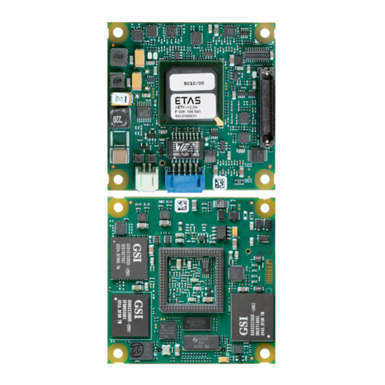
ETAS XETK-V2.0 Series User Manual (103 pages)
Emulator Probe for MPC5600 and SPC5600 Family
Brand:
ETAS
| Category:
Control Unit
| Size: 3 MB
Table of Contents
Table of Contents
3
1 About this Manual
7
Identification of Safety Notices
7
Presentation of Information
7
Scope of Supply
8
Additional Information
8
2 Basic Safety Notices
9
General Safety Information
9
Requirements for Users and Duties for Operators
9
Intended Use
9
Identifications on the Product
12
Fig. 2-1 Adhesive Label (Example: Label for XETK-S14.0)
12
Taking the Product Back and Recycling
13
CE Marking
13
Rohs Conformity
13
European Union
13
China
13
Fig. 2-2 WEEE-Symbol
13
Declarable Substances
14
Use of Open Source Software
14
3 Introduction
15
Applications
15
Fig. 3-1 XETK-V2.0 Top View
15
Features
16
4 Hardware Description
18
Overview
18
XETK-V2.0 Variants
18
XETK-V2.0A/C Vertical Interface Concept
19
Fig. 4-1 Vertical Interface Concept (Side View)
19
Fig. 4-3 Vertical Base Board (Fitted with Pin Array/ BGA Adapter, Side View)
20
XETK-V2.0B Interface Concept
21
Architecture
21
Fig. 4-4 XETK-V2.0 Architecture
21
ECU Interface
22
Fig. 4-5 XETK-V2.0A/C ECU Interface CON1
22
Fig. 4-6 XETK-V2.0B ECU Interface CON5
22
Power Supply
23
Fig. 4-7 Power Supply Monitoring
23
Fig. 4-8 Power Supply Connector CON2 (Left: XETK-V2.0A/C, Right: XETK-V2.0B)
23
XETK Ethernet Interface
24
Fig. 4-9 Power Supply Connectors CON2 and CON3
24
Status Leds
25
Fig. 4-10 Location of the Ethernet Interface CON4
25
Reset
26
Data Emulation Memory
26
Fig. 4-11 Status Leds
26
Page Switching
27
XETK-V2.0A/C SRAM Characteristics & Data Retention
28
Data Emulation Power Failures
29
Nexus (JTAG) Interface
29
Xetk-V2.0A/C
29
Fig. 4-12 Equivalent Circuitry of the XETK-V2.0A/C Nexus (JTAG) Interface
29
Xetk-V2.0B
30
Fig. 4-13 Equivalent Circuitry of the XETK-V2.0B Nexus (JTAG) Interface
30
Watchdog Timer Disable / Tool Detect Interface
31
Xetk-V2.0A/C
31
Fig. 4-14 Equivalent Circuitry of the XETK-V2.0A/C WDT Interface Via Vertical (BGA)
32
Xetk-V2.0B
33
Startup and Triggering with DAI Pins
33
XETK-V2.0A/C DAI Interface Via BGA Vertical Base Boards
33
Fig. 4-15 Equivalent Circuitry of the XETK-V2.0B WDT Interface
33
XETK-V2.0A/C DAI Interface Via QFP Vertical Base Boards
34
Fig. 4-2 Vertical Base Board
34
Fig. 4-16 Equivalent Circuitry of the XETK-V2.0A/C DAI Interface Via Vertical (BGA)
34
XETK-V2.0B DAI Interface
35
Fig. 4-17 Equivalent Circuitry of the XETK-V2.0A/C DAI Interface Via Vertical (QFP)
35
Phases of the Startup Protocol
36
Fig. 4-18 Equivalent Circuitry of the XETK-V2.0B DAI Interface
36
Triggering of Measurement Data Acquisition
37
Fig. 4-19 Phases of the Startup Protocol (XETK Connected)
37
Pinless Startup and Triggering
38
Startup Handshake
38
Triggering of Measurement Data Acquisition
39
Triggering with Timers
39
Triggering with Trace
39
XETK-V2.0A/C Microcontroller EBI Voltage Supply
40
XETK-V2.0A/C Nexus (JTAG) Debugger Interface
40
Fig. 4-20 Location of the XETK-V2.0A/C Nexus (JTAG) Debugger Interface
40
Braindead Flashing
41
Braindead Flashing Via Nexus (JTAG) Debug Interface
41
External Watchdog Disable
42
5 Installation
43
Connection to the ECU
43
Xetk-V2.0A/C
43
Fig. 5-1 XETK-V2.0 Connection to the ECU with Socket/Adapter
43
Xetk-V2.0B
44
Fig. 5-2 XETK-V2.0B Connection to the ECU with Socket/Adapter
44
Wiring
45
XETK Ethernet Interface
45
Fig. 5-3 Wiring - XETK Ethernet Interface
45
Power Supply
46
Fig. 5-4 Wiring - Permanent Power Supply Inside ECU Available
46
Fig. 5-5 Wiring - Permanent Power Supply Inside ECU Not Available
46
Fig. 5-6 Wiring - Isolated Power Supply Inside ECU
47
6 XETK Configuration
48
Overview
48
Configuration Parameter
48
7 Technical Data
50
System Requirements
50
ETAS Hardware
50
Ethernet Interface of the PC
50
Supported Microcontrollers and Software Versions
50
Environmental Conditions
51
Power Supply
52
Xetk-V2.0A/C
52
Xetk-V2.0B
52
Configuration
53
XETK Ethernet Interface
53
ECU Interface Characteristics
54
Xetk-V2.0A/C
54
Xetk-V2.0B
54
Test Characteristics
55
Electrical Characteristics
56
Xetk-V2.0A/C
56
Xetk-V2.0B
63
Switching Characteristics
65
JTAG Timing Characteristics
65
Fig. 7-1 XETK-V2.0 JTAG Timing Diagram
65
Nexus Timing Characteristics
66
XETK-V2.0A/C SRAM Read Timing
66
Fig. 7-2 XETK-V2.0 Nexus Timing Diagram (Valid up to 66 Mhz)
66
Fig. 7-3 SRAM Read Cycle
66
XETK-V2.0A/C SRAM Write Timing
67
Fig. 7-4 SRAM Write Cycle
67
Mechanical Dimensions
68
Xetk-V2.0A/C
68
Fig. 7-5 XETK-V2.0A/C Dimensions - Top View
68
Fig. 7-6 XETK-V2.0A/C Dimensions - Side View
69
Fig. 7-7 XETK-V2.0A/C Vertical Connector Pin A1 Indicator - Top View
69
Xetk-V2.0B
70
Fig. 7-8 XETK-V2.0B Dimensions - Top View
70
Fig. 7-9 XETK-V2.0B Dimensions - Side View
71
Pin Assignment
72
XETK-V2.0A/C Vertical Connector
72
Fig. 7-10 Vertical Connector
72
XETK-V2.0A/C Nexus (JTAG) Debugger Interface
77
Fig. 7-11 XETK-V2.0A/C Samtec Connector
77
XETK-V2.0B ECU Interface
79
Fig. 7-12 XETK-V2.0B Samtec Connector
79
8 Cables and Accessories
81
ECU Adapter Cable
81
CBAM230.1 Adapter Cable
81
CBAM240.1 Adapter Cable
81
Fig. 8-1 CBAM230.1 Adapter Cable
81
Fig. 8-2 CBAM240.1 Adapter Cable
81
PC Interface Cable
82
CBE200-3 Cable
82
CBAE200.2 Adapter Cable
82
Fig. 8-3 CBE200-3 Cable
82
Fig. 8-4 CBAE200.2 Adapter Cable
82
ETAS Module Interface Adapter Cable
83
CBE230.1 Cable
83
CBAE330.2 Adapter Cable
83
Fig. 8-5 CBE230.1 Cable
83
Fig. 8-6 CBAE330.2 Adapter Cable
83
Power Supply Cables
84
Cable ETV
84
Cable K70
84
Cable KA50
84
Fig. 8-7 Cable ETV
84
Fig. 8-8 Cable K70
84
Fig. 8-9 Cable KA50
84
Cable CBM200
85
Fig. 8-10 Cable CBM200
85
Adapters
86
ETAH1 ECU Interface Adapter for XETK-V2.0B
86
Fig. 8-11 ETAH1 XETK-V2.0B - ECU Adapter Cable
86
Fig. 8-12 ETAH1 Dimensions - Top View
86
Fig. 8-13 ETAH1 Samtec - Mictor (50Mc - 38Mc)
87
ETAH2 Debugger Interface Adapter for XETK-V2.0A/C
89
Fig. 8-14 ETAH2 XETK-V2.0A/C - Debugger Adapter Cable
89
Fig. 8-15 ETAH2 Dimensions - Top View
89
Fig. 8-16 ETAH2 Samtec - Samtec (50Mc - 50Fc)
90
ETAH5 Debugger Interface Adapter for XETK-V2.0A/C
91
Fig. 8-17 ETAH5 XETK-V2.0A/C - Debugger Adapter Cable
91
Fig. 8-18 ETAH5 Dimensions - Top View
91
ETAH4 ECU Interface Adapter for XETK-V2.0B
92
Fig. 8-19 ETAH5 Samtec - Samtec (50Mc - 50Fc)
92
Fig. 8-20 ETAH4 XETK-V2.0B - ECU Adapter Cable
92
Fig. 8-21 ETAH4 Dimensions - Top View
93
Fig. 8-22 ETAH1 Samtec - Mictor (50Mc - 38Mc)
93
9 Ordering Information
94
Xetk-V2.0
94
XETK-V2.0A/C - Debugger Adapter
94
XETK-V2.0B - ECU Adapter
95
Vertical Base Boards
95
Sockets ECU - Vertical Base Board
95
Connector XETK-V2.0B - ECU Adapter ETAH1
95
Connector XETK-V2.0B - ECU Adapter ETAH4
96
Cables
97
ECU Adapter Cables
97
Ethernet Cables
97
Power Supply Cables
98
Power Supply
98
10 ETAS Contact Addresses
99
Figures
100
Index
102
Advertisement
Advertisement
Related Products
ETAS XETK-V2.0A
ETAS XETK-V2.0B
ETAS XETK-V2.0C
ETAS XETK-V1.0
ETAS XETK-S4.2
ETAS XETK-S14.0
ETAS BR XETK-S1.0
ETAS XETK-S22.0
ETAS BR XETK-S3.0
ETAS XETK-S31.0
ETAS Categories
Control Unit
Computer Hardware
Measuring Instruments
Recording Equipment
I/O Systems
More ETAS Manuals
Login
Sign In
OR
Sign in with Facebook
Sign in with Google
Upload manual
Upload from disk
Upload from URL