
Related Manuals for WAGO Pro 2


Summary of Contents for WAGO Pro 2
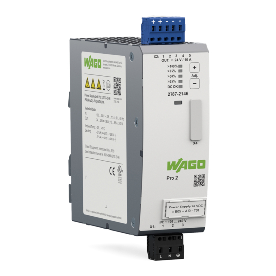
- Page 1 Power Supplies Power Supply Pro 2; 1-phase, 24 VDC, 10 A, 240 W 2787-2146 (/0000-00x0) Product manual | Version 1.2.2...
- Page 2 We wish to point out that the software and hardware terms as well as the trademarks of companies used and/or mentioned in the present manual are generally protected by trademark or patent. WAGO is a registered trademark of WAGO Verwaltungsgesellschaft mbH. Product manual | Version: 1.2.2 Power Supply Pro 2...
-
Page 3: Table Of Contents
Product Protection .................. 24 3.9.9 Security ...................... 24 3.9.10 3.10 Guidelines, approvals and standards .............. 25 Guidelines .................... 25 3.10.1 Approvals ..................... 25 3.10.2 Standards ..................... 26 3.10.3 Special Requirements .................. 28 3.10.4 Product manual | Version: 1.2.2 Power Supply Pro 2... - Page 4 Operation via Buttons.................... 35 Diagnostics........................ 36 Diagnostics via Indicators.................. 36 Configuration........................ 37 10.1 Requirements ...................... 37 System Requirements .................. 37 10.1.1 Install WAGO Interface Configuration Software ........... 37 10.1.2 Configure Product .................. 37 10.1.3 10.2 First Steps ...................... 38 Starting the Software .................. 38 10.2.1 10.3 Overview .......................
- Page 5 “Top Boost” Mode.................. 68 11.6.7 11.7 Maintenance...................... 69 Decommissioning ...................... 70 12.1 Disposal and Recycling .................. 70 Appendix......................... 71 13.1 Application Notes .................... 71 AC Operation.................... 71 13.1.1 13.2 Accessories ...................... 72 13.3 Protected Rights.................... 73 Product manual | Version: 1.2.2 Power Supply Pro 2...
-
Page 6: Provisions
All the documentation and information is available at: ü www.wago.com. 1.1 Intended Use The 2787 Series WAGO Power Supply Pro 2 provides DC voltage to electrical or elec- tronic devices, such as industrial control systems or display, communication and measur- ing devices. -
Page 7: Typographical Conventions
The terms set forth in the General Business and Contract Conditions for Delivery and Service of WAGO GmbH & Co. KG and the terms for software products and products with integrated software stated in the WAGO Software License Contract – both available at ü www.wago.com... - Page 8 Type and source of malfunction (property damage only) Possible malfunctions that may restrict the product’s scope of functions or ergonomics, but do not lead to foreseeable risks to persons • Action step to reduce risk Product manual | Version: 1.2.2 Power Supply Pro 2...
-
Page 9: Legal Information
Third-party products are always mentioned without any reference to patent rights. WAGO GmbH & Co. KG, or for third-party prod- ucts, their manufacturer, retain all rights regarding patent, utility model or design registra- tion. -
Page 10: Safety
• Only operate the product when the ground conductor is connected. • Protect the product with an appropriate overcurrent protection device. Conductors • Only use conductor cross-sections sufficient for the current load. • Observe permissible temperature range of connecting cables. Product manual | Version: 1.2.2 Power Supply Pro 2... -
Page 11: Mechanical Safety
2787-2146 (/0000-00x0) Safety • Only clamp one conductor to each connection terminal. If several conductors must be clamped, wire them using an upstream wiring assembly (e.g., WAGO Through Termi- nal Blocks). • Use appropriate strain relief. 2.3 Mechanical Safety • As the installer of the system, you are responsible for ensuring the necessary touch- proof protection. -
Page 12: Properties
The Power supplies can be configured directly via buttons on the product or via the inte- grated communication interface. For this purpose, the connection is established either via the WAGO USB Communication Cable or via an attached communication module. It is also possible to record and evaluate various output parameters via the WAGO Interface Configuration software, which is available separately. -
Page 13: Type Label
Class I Equipment Indoor Use Only ; IP20 See installation manual No. 9970-0966/2787-2146 IND. CONT. EQ. 3VR3 WAGO is a registered trademark of WAGO Verwaltungsgesellschaft mbH. Figure 2: Type label Table 4: Legend for Figure “Type label” Position Comment For Details, See Section Company logo and address –... -
Page 14: Label
2D data matrix code Contains the information from positions 2 … 5 Key number Fixed information (37S) ID number per D-U-N-S® Fixed information (WAGO Minden) WAGO item number or internal SAP number Product-specific Consecutive number Product-specific Production date and revision • Production date •... -
Page 15: Input
Contact “–” for output voltage Contact “+” for output voltage Contact “+” for output voltage Test slot Table 10: Details – Output Connection 8 Accessories Series 721 Series (see section [} 73]) ® Connection Technology CAGE CLAMP Product manual | Version: 1.2.2 Power Supply Pro 2... -
Page 16: Signal
Table 14: Indication of Operating States – Output Power Indicator DC OK / Output Output Power Output Power Output Power Output Power Power < 25 % ≥ 25 % … < 50 % ≥ 50 % … < 75 % ≥ 75 % … ≥ 100 % < 100 % > 100 % Steady > 75 % Steady Steady Product manual | Version: 1.2.2 Power Supply Pro 2... -
Page 17: Control Elements
Save the cap so you can re-close the communication interface after use. This prevents contamination or foreign matter from getting into the open communication interface. Note Avoid external interference couplings! Unusual external interference couplings can lead to communication limitations! Product manual | Version: 1.2.2 Power Supply Pro 2... -
Page 18: Technical Data
If you use a communication module, the corresponding communication module is de- & Product scribed in the Manual. To connect to a PC with the WAGO USB Communication Cable, perform the following steps: 1. Remove the cap. 2. Connect the USB connector of the WAGO USB Communication Cable to your PC. -
Page 19: Input
Holding time, typ. 110 VAC 37 ms 230 VAC 37 ms At nominal load Table 19: Technical Data – Input Connection Property Value Cross-section Solid 0.08 … 2.5 mm² / 28 … 12 AWG Product manual | Version: 1.2.2 Power Supply Pro 2... -
Page 20: Output
10 % / 90 % load step 20 MHz bandwidth 8 Short-Circuit and Overload Behavior [ } 64] See section Can be set via the WAGO Interface Configuration software See figure “Turn-on Time” Product manual | Version: 1.2.2 Power Supply Pro 2... -
Page 21: Efficiency/Power Loss
3.9.4 Efficiency/Power Loss Table 22: Technical Data – Efficiency/Power Loss Property Value Efficiency, typ. 110 VAC 93.5 % 230 VAC 95.2 % Power loss, typ. 110 VAC 16.4 W 230 VAC 12.0 W At nominal load Product manual | Version: 1.2.2 Power Supply Pro 2... -
Page 22: Signal
24 VDC Table 24: Technical Data – Signal (Output DO) Property Value Switch-on threshold, typ. UOUT > USET × 0.93 Switch-off threshold, typ. UOUT < USET × 0.87 Contact load, max. 50 mA Product manual | Version: 1.2.2 Power Supply Pro 2... -
Page 23: Communication
5 … 96 % (no condensation permissible) Elevation above sea level, max. 5000 m Overvoltage category III (≤ 2000 m) II (> 2000 m) Vibration according to IEC 60068-2-6 5 … 150 Hz / 1g Product manual | Version: 1.2.2 Power Supply Pro 2... -
Page 24: Product Protection
Isolation voltage (output – ground), ref. C 500 VAC Isolation voltage (output – digital input / 500 VAC output – digital output), ref. D Type test (rise 5 s – stay 2 s – fall 5 s); see figure “Dielectric Strength” Product manual | Version: 1.2.2 Power Supply Pro 2... -
Page 25: Guidelines, Approvals And Standards
(Ordinary Locations) Underwriters Laboratories Inc. UL 61010-2-201 (Ordinary Locations) 1) 2) Underwriters Laboratories Inc. UL 121201 (Hazardous Locations) 1) 2) DNV GL CG-0339 Only applies to 2787-2146/0000-0030 Only applies to 2787-2146/0000-0070 Product manual | Version: 1.2.2 Power Supply Pro 2... -
Page 26: Standards
Safety requirements for electrical equipment for measurement, control, and laboratory use - Part 2-201: Particular requirements for control equipment EN 61010-1 Safety requirements for electrical equipment for measurement, control, and laboratory use - Part 1: General requirements Product manual | Version: 1.2.2 Power Supply Pro 2... - Page 27 80 % of 100 VAC (50 250/300 cycles … 60 Hz) 0 % of 100 VAC (50 250/300 cycles … 60 Hz) Table 38: Legend for “Standards: EMC – Immunity to Interference (Tests Performed)” Category Description Normal operation within specification limits Product manual | Version: 1.2.2 Power Supply Pro 2...
-
Page 28: Special Requirements
• Commencement of normal operation is allowed only on the condition of compliance with the EMC Directive. • The manufacturer of the system or machine is responsible for ensuring compliance with the limit values required by EMC legislation. Product manual | Version: 1.2.2 Power Supply Pro 2... -
Page 29: Functions
Configurable load management For details, see section Dialog:Settings. Communication interface Allows connection via a WAGO USB Communication Cable (see section Communication Interface) or via a communication module that is available as an option. The communication modules allow configuration and monitoring of the product via fieldbus systems. -
Page 30: Transport And Storage
• Only transport the product in suitable containers/packaging. • Make sure the product contacts are not contaminated or damaged during packing or unpacking. • Observe the specified ambient climatic conditions for transport and storage (8 Techni- cal data [} 18]). Product manual | Version: 1.2.2 Power Supply Pro 2... -
Page 31: Installation And Removal
The DIN-35 rail is located in the center of the vertical axis (height) of the product (see section 8 Technical Data [} 18]). Figure 14: Position of the DIN-35 rail The distances from the central axis of the DIN-35 rail to the top and bottom are 65 mm. Product manual | Version: 1.2.2 Power Supply Pro 2... - Page 32 1. To remove (see figure “Removing”), pull the latch (I) down [C], using a screwdriver or an operating tool. 2. Pivot the product to remove it from the DIN-35 rail [D]. Product manual | Version: 1.2.2 Power Supply Pro 2...
-
Page 33: Connection
This product is suitable for use in Class I, Division 2, Groups A, B, C and D or non-haz- ardous locations only. 7.2 Connect Conductor to CAGE CLAMP® ® CAGE CLAMP Connectors are designed for solid, stranded and fine-stranded conduc- tors. Product manual | Version: 1.2.2 Power Supply Pro 2... - Page 34 If more than one conductor must be routed to one connection, these must be connected in an up-circuit wiring assembly, for example, using WAGO Through Terminal Blocks. To connect the conductors, use an operating tool (see section Accessories) or an appro- priate screwdriver.
-
Page 35: Operation
During ongoing operation, you can set the output voltage and reset the product to the fac- tory settings. These settings can be saved and then remain available when the product is switched off and back on. Product manual | Version: 1.2.2 Power Supply Pro 2... -
Page 36: Diagnostics
Shutdown Fault face > 100 % Flashing (8 Hz) Flashing (8 Hz) Flashing (8 Hz) Flashing (8 Hz) > 75 % Steady Flashing (8 Hz) > 50 % Flashing (8 Hz) > 25 % Flashing (8 Hz) DC OK Flashing (8 Hz) Steady Automatic restart (factory setting) Product manual | Version: 1.2.2 Power Supply Pro 2... -
Page 37: Configuration
2787-2146 (/0000-00x0) Configuration Configuration 10.1 Requirements 10.1.1 System Requirements The following system requirements must be met for the WAGO Interface Configuration software to be installed: Minimum System Requirements Table 47: Minimum System Requirements Components Requirements Operating system • Windows 7 (32- and 64-bit) •... -
Page 38: First Steps
Configuration 2787-2146 (/0000-00x0) The following requirements must be met before you can work online with the WAGO In- terface Configuration software: • The product must be connected to the computer on which the WAGO Interface Config- uration software is installed. -
Page 39: Backstage" Tab
On this tab, you can make the following settings: 1. Select the Communication menu item. 2. In the “Communication Settings” dialog, under COM Port, select the corresponding entry for your connection between the computer and the product (example: WAGO USB service cable). 3. Click [Save]. - Page 40 Connect menu item. The software automatically detects which product is connected. Your product is connected to the software. You can now use the software to address, configure and evaluate your product. Product manual | Version: 1.2.2 Power Supply Pro 2...
- Page 41 The Display section shows parameter settings and recorded time series in graphical form. You can find more information in section Display Section. Product Information This section contains information on the connected product. Product manual | Version: 1.2.2 Power Supply Pro 2...
-
Page 42: Dialog: Settings
[} 52]. Update Performs a firmware update on the product. You can get the current firmware update and corre- sponding compatibility information from WAGO Tech- nical Support. Recovery Restores any firmware version. This may be necessary if a current firmware update has failed and a connection to the connected product cannot be established. - Page 43 Writes all the settings that have been made to the connected product. [Close] Closes the dialog. Any settings that have not been saved are lost. The individual sections of the dialog are described below. Product manual | Version: 1.2.2 Power Supply Pro 2...
- Page 44 Constant current (latching If this checkbox is selected, the “Constant Current with mode) Latching Shutdown” overload behavior is enabled. You can find more information in section 8 “Constant Current with Latching Shutdown” Mode [} 65]. Product manual | Version: 1.2.2 Power Supply Pro 2...
- Page 45 If this checkbox is selected, the “Top Boost” overload behavior is enabled. The power supply provides up to 600 % more output power for 15 s. You can find more information in section 8 “Top Boost” Mode [} 68]. Product manual | Version: 1.2.2 Power Supply Pro 2...
- Page 46 If this checkbox is selected, the digital output is set if (latched) latching shutdown occurs. Digital output via process If this checkbox is selected, the digital output can be data/communication controlled via the process data. Product manual | Version: 1.2.2 Power Supply Pro 2...
- Page 47 You can enter after how many operating hours (unit: h) ing limit after which a warning message is generated. These parameters are not mutually exclusive and can also be selected simultaneously. Product manual | Version: 1.2.2 Power Supply Pro 2...
- Page 48 If this checkbox is selected, a button lock feature is ac- tivated. No functions can be performed with the but- tons. However, it is still possible to reset the product to the factory settings. Product manual | Version: 1.2.2 Power Supply Pro 2...
- Page 49 All the input fields can be freely edited. You Function name can enter up to 32 characters into each input field. Customer information These parameters are mutually exclusive and can only be selected individually. Product manual | Version: 1.2.2 Power Supply Pro 2...
- Page 50 You can enter the password here. The password can consist of at most eight characters (from the ASCII character set). Show password If this checkbox is selected, the password entered is shown without encryption. Product manual | Version: 1.2.2 Power Supply Pro 2...
- Page 51 Modbus This section contains specific parameters for the Modbus RTU Communication Module. The configured parameters are first transferred to the WAGO Power Supply Pro 2. As soon as the Modbus RTU Communication Module is attached, the parameters are used here accordingly.
-
Page 52: Dialog: Simulation
2787-2146 (/0000-00x0) 10.3.1.2.2 Dialog: Simulation In this dialog, you an adjust the individual setting options of a WAGO Power Supply Pro 2 on the software side. No physical WAGO Power Supply Pro 2 is required. The individual setting options are used exclusively for simulation and test purposes and are not trans- ferred to any connected WAGO Power Supply Pro 2. - Page 53 Hides the selected operation panel and anchors the operation panel as a tab on the outer edge of the dia- log. Closes the selected operation panel. “Control panel Pro 2” Optical Displays the connected local [unit: %]. You can set the Operation Panel...
- Page 54 Displays the last accumulated error and warning mes- Operation Panel sages. General information on accumulated error and warning 8 Display Sec- messages is explained in the Section tion: Last Error and Warning Messages [} 60]. Product manual | Version: 1.2.2 Power Supply Pro 2...
-
Page 55: Main Menu
The representation in the Display section is described in section Display Sec- tion: Information. 10.3.3 Display Section The Display section differs according to the menu item selected in the main menu. Product manual | Version: 1.2.2 Power Supply Pro 2... -
Page 56: Display Section: Measurements
(unit: W·s). Last minute This indicates the output energy supplied in the last minute (unit: W·s). Last hour This indicates the output energy supplied in the last hour (unit: W·h). Product manual | Version: 1.2.2 Power Supply Pro 2... - Page 57 The standby time of the product (unit: h) is displayed. Operating Time The operating time of the product (unit: h) is displayed. When Power Boost or Top Boost is output, this is signaled for 5 s. Product manual | Version: 1.2.2 Power Supply Pro 2...
-
Page 58: Display Section: Measurement Recording
Here you can enter the number of measured values to record (setting at pos. 1 = chart). Sample rate Here you can enter the recording cycle for the mea- sured values (unit: ms) Product manual | Version: 1.2.2 Power Supply Pro 2... - Page 59 Starts the recording (setting at pos. 1 = chart). [Stop] Stops the recording before the specified number is reached (setting at pos. 1 = chart). – This shows the time series for the selected measured value. Product manual | Version: 1.2.2 Power Supply Pro 2...
-
Page 60: Display Section: Last Error And Warning Messages
Up to 20 error messages and warnings are shown in the display section. The display section is a so-called “ring memory”: If the display section is full, existing error messages and warnings are overwritten by accumulating error messages and warnings. Product manual | Version: 1.2.2 Power Supply Pro 2... -
Page 61: Display Section: Information
SW-Version This shows the current release of the software version (firmware). HW-Version: This shows the current release of the hardware version. Config ID: This shows the configuration ID of the product. Product manual | Version: 1.2.2 Power Supply Pro 2... -
Page 62: Notes On Operation
Remove the screw (d) on the side of the product. ð The overvoltage protection is disabled. Enable Overvoltage Protection • Screw in the screw (d) on the side of the product. ð The overvoltage protection is enabled. Product manual | Version: 1.2.2 Power Supply Pro 2... -
Page 63: Inrush Current
High inrush currents can occur if multiple products are supplied through the same circuit on the input side. In this case, it is advisable to switch the WAGO Power Supply Pro 2 on with a delay. The corresponding switch-on delay can be parameterized in the Dialog: Set- tings dialog in the “System”... -
Page 64: Derating (Location-Dependent)
This smooth characteristic curve ensures better current sharing for parallel operation of power supplies. This setting can be enabled in the Dialog: Settings dialog in the “DC Out- put” section of the WAGO Interface Configuration software. 11.6 Short-Circuit and Overload Behavior The product’s output is electronically protected against overload and short circuits. -
Page 65: Constant Current" Mode
If the overload lasts longer, the output is switched off. To switch the output back on, man- ual intervention is necessary. The following options are available for this: • Communication interface • Buttons • Digital input Product manual | Version: 1.2.2 Power Supply Pro 2... -
Page 66: Hiccup" Mode
100% 500ms Figure 41: “Hiccup” Mode 11.6.4 “Electronic Circuit Breaker” Mode In this mode, a specified trip current and trip delay can be set via the WAGO Interface 8 communication module Configuration software or a connected [} 72]. If the output current exceeds the trip current setting, a specified amount of time elapses. If the output current is still higher than the trip current setting after the trip delay corresponding to the setting, the output is switched off. -
Page 67: Latching Shutdown On Thermal Overload" Mode
In this mode, the output voltage is switched off in the event of excessive internal device temperature. A corresponding “High Device Temperature” warning can, for example, be transmitted via the WAGO Interface Configuration software or passed to a higher-level 8 communication module controller via a connected [} 72]. -
Page 68: Top Boost" Mode
In addition, calculate the error loop impedance. The maximum current that can flow through the error loop (due to the impedance) must not be lower than trip current of the overcurrent protection device necessary to reliably trip it. Product manual | Version: 1.2.2 Power Supply Pro 2... -
Page 69: Maintenance
Permitted repairs are limited to the measures listed in these operating instructions. Should a fault occur nonetheless, return the product to WAGO for repair. Provide the fol- lowing information: • Type of fault •... -
Page 70: Decommissioning
• Have electrical and electronic equipment sent to a local collection point. • The guidelines 2006/66/EG, PPWD 2018/852/EU and WEEE 2012/19/EU apply throughout Europe. National directives and laws may vary. Product manual | Version: 1.2.2 Power Supply Pro 2... -
Page 71: Appendix
2787-2146 (/0000-00x0) Appendix Appendix 13.1 Application Notes The following figures illustrate examples of how a WAGO Power Supply Pro 2 can be connected as a consumer in three different grounding systems: TN, TT and IT. 13.1.1 AC Operation Source (AC);... -
Page 72: Accessories
IO-Link Communication Module 2789-9080 WAGO Power Supply Pro 2 Attachable Modbus RTU Communication Mod- Modbus RTU Communication 2789-9015 ule for WAGO Power Supply Pro 2 Module Attachable Modbus TCP Communication Mod- Modbus TCP Communication 2789-9052 ule for WAGO Power Supply Pro 2... -
Page 73: Protected Rights
• QR Code is a registered trademark of DENSO WAVE INCORPORATED. ® • Subversion is a trademark of the Apache Software Foundation. ® • Windows is a registered trademark of Microsoft Corporation. Product manual | Version: 1.2.2 Power Supply Pro 2... - Page 74 Table 33 Standards: Mechanical and Climatic Environmental Conditions........Table 34 Standards: EMC – Immunity to Interference..............Table 35 Standards: EMC – Emission of Interference..............Table 36 Standards: LVD – Low Voltage Directive................Product manual | Version: 1.2.2 Power Supply Pro 2...
- Page 75 Derating (Temperature-Dependent)................... Table 68 Derating (Location-Dependent)..................Table 69 WEEE Mark ........................Table 70 Accessories – Communication................... Table 71 Accessories – Tools......................Table 72 Accessories – Marking....................... Table 73 Accessories – Spare Parts....................Product manual | Version: 1.2.2 Power Supply Pro 2...
- Page 76 Main Menu ........................Figure 33 Display Section: “Measurements” ................. Figure 34 Display Section: “Measurement Recording” ..............Figure 35 Display Section: “Last Error and Warning Messages” ..........Figure 36 Display Section: “Information” ..................Product manual | Version: 1.2.2 Power Supply Pro 2...
- Page 77 “Power Boost” Mode in Combination with “Constant Current” Mode ......Figure 44 Loop Impedance ......................Figure 45 AC input ........................Figure 46 TN Network ........................Figure 47 TT Network........................Figure 48 IT Network........................Product manual | Version: 1.2.2 Power Supply Pro 2...
- Page 78 WAGO is a registered trademark of WAGO Verwaltungsgesellschaft mbH. Copyright – WAGO GmbH & Co. KG – All rights reserved. The content and structure of the WAGO websites, catalogs, videos and other WAGO media are subject to copyright. Distri- bution or modification of the contents of these pages and videos is prohibited. Furthermore, the content may neither be copied nor made available to third parties for commercial pur-...
Need help?
Do you have a question about the Pro 2 and is the answer not in the manual?
Questions and answers