Sign In
Upload
Manuals
Brands
WAGO Manuals
Power Supply
I/O-SYSTEM 750-610
WAGO I/O-SYSTEM 750-610 Manuals
Manuals and User Guides for WAGO I/O-SYSTEM 750-610. We have
2
WAGO I/O-SYSTEM 750-610 manuals available for free PDF download: Manual
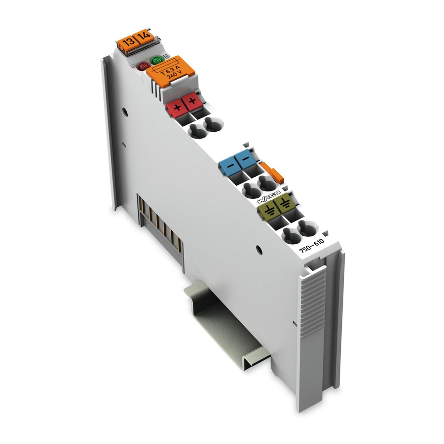
WAGO I/O-SYSTEM 750-610 Manual (48 pages)
24V DC Power Supply/Fuse/Diagn. Supply Module DC 24 V, Fuse, Diagnostics
Brand:
WAGO
| Category:
Power Supply
| Size: 2.15 MB
Table of Contents
Table of Contents
3
1 Notes about this Documentation
5
Validity of this Documentation
5
Copyright
5
Symbols
6
Number Notation
8
Font Conventions
8
Table 1: Number Notation
8
Table 2: Font Conventions
8
2 Important Notes
9
Legal Bases
9
Subject to Changes
9
Personnel Qualifications
9
Use of the WAGO-I/O-SYSTEM 750 in Compliance with Underlying Provisions
9
Technical Condition of Specified Devices
10
Safety Advice (Precautions)
11
3 Device Description
13
View
14
Figure 1: View
14
Table 3: Legend for Figure "View
14
Connectors
15
Data Contacts/Internal Bus
15
Figure 2: Data Contacts
15
Power Jumper Contacts/Field Supply
16
Figure 3: Power Jumper Contacts
16
Table 4: Legend for Figure "Power Jumper Contacts
16
CAGE CLAMP ® Connectors
17
Figure 4: CAGE CLAMP ® Connections
17
Table 5: Key for "CAGE CLAMP ® Connections" Figure
17
Display Elements
18
Operating Elements
18
Schematic Diagram
18
Figure 5: Indicating Elements
18
Figure 6: Schematic Diagram
18
Table :6 Key for the "Display Elements" Figure
18
Technical Data
19
Device Data
19
Power Supply
19
Connection Type
19
Table 7: Technical Data, Device
19
Table 8: Technical Data, Power Supply
19
Table 9: Technical Data - Field Wiring
19
Table 10: Technical Data - Power Jumper Contacts
19
Table 11: Technical Data - Data Contacts
19
Climatic Environmental Conditions
20
Table 12: Technical Data - Climatic Environmental Conditions
20
Approvals
21
Standards and Guidelines
23
4 Process Image
24
Table 13: Input Bits
24
5 Mounting
25
Mounting Sequence
25
Inserting and Removing Devices
26
Inserting the I/O Module
26
Figure 7: Insert I/O Module (Example)
26
Figure 8: Snap the I/O Module into Place (Example)
26
Removing the I/O Module
27
Figure 9: Removing the I/O Module (Example)
27
6 Connect Devices
28
Connecting a Conductor to the CAGE CLAMP
28
Figure 10: Connecting a Conductor to a CAGE CLAMP
28
Power Supply Concept
29
Supplementary Power Supply Regulations
29
Figure 11: Power Supply Concept
29
7 Startup and Service
30
Fuse Installation or Replacement
30
Figure 12: Removing the Fuse Holder
30
Figure 13: Opening the Fuse Holder
31
Figure 14: Replacing the Fuse
31
8 Use in Hazardous Environments
32
Marking Configuration Examples
33
Marking for Europe According to ATEX and IEC-Ex
33
Figure 15: Side Marking Example for Approved I/O Modules According to ATEX and Iecex
33
Figure 16: Text Detail - Marking Example for Approved I/O Modules According to ATEX and Iecex
33
Table 14: Description of Marking Example for Approved I/O Modules According to ATEX and Iecex
34
Figure 17: Side Marking Example for Approved Ex I I/O Modules According to ATEX and Iecex
35
Figure 18: Text Detail - Marking Example for Approved Ex I I/O Modules According to ATEX and Iecex
35
Table 15: Description of Marking Example for Approved Ex I I/O Modules According to ATEX and Iecex
36
Marking for America According to NEC 500
38
Figure 19: Side Marking Example for I/O Modules According to NEC 500
38
Figure 20: Text Detail - Marking Example for Approved I/O Modules According to NEC 500
38
Table 16: Description of Marking Example for Approved I/O Modules According to NEC 500
38
Installation Regulations
39
Special Conditions for Safe Use (ATEX Certificate TÜV 07 ATEX 554086 X)
40
Special Conditions for Safe Use (ATEX Certificate TÜV 12 ATEX 106032 X)
41
Special Conditions for Safe Use (IEC-Ex Certificate TUN 09.0001
42
Special Conditions for Safe Use (IEC-Ex Certificate Iecex TUN 12.0039 X)
43
Special Conditions for Safe Use According to ANSI/ISA
44
List of Figures
45
List of Tables
46
Advertisement
WAGO I/O-SYSTEM 750-610 Manual (14 pages)
Fieldbus Independent I/O Modules 24 V DC Power Supply/Fuse/Diagn.
Brand:
WAGO
| Category:
I/O Systems
| Size: 0.3 MB
Table of Contents
Table of Contents
3
1 Important Comments
4
Legal Principles
4
Copyright
4
Personnel Qualification
4
Intended Use
4
Symbols
5
Number Notation
5
Safety Notes
6
Scope
6
2 O Modules
7
System Modules
7
750-610 [24 V DC Power Supply/Fuse/Diagn.]
7
View
7
Description
7
Display Elements
8
Schematic Diagram
9
Technical Data
10
Process Image
11
Power Supply Concept
11
Advertisement
Related Products
WAGO 750-601/040-000
WAGO 750-610/040-000
WAGO 750-625/000-001
WAGO 787-1211
WAGO 787-1202
WAGO 787-1212
WAGO 787-1216
WAGO 787-1226
WAGO 787-1200
WAGO EPSITRON 787-1675
WAGO Categories
I/O Systems
Control Unit
Power Supply
Switch
Controller
More WAGO Manuals
Login
Sign In
OR
Sign in with Facebook
Sign in with Google
Upload manual
Upload from disk
Upload from URL