Table of Contents
Advertisement
Pos : 2 /D okumentati on allgemein/Ei nband/Ei nband H andbuch - Dec kbl att ohne Variantenfel d (Standar d) @ 9\mod_1285229289866_0.doc @ 64941 @ @ 1
Manual
EPSITRON®
Switched-Mode Power Supply with Integrated
UPS Charger and Controller
787-1675
Version 1.0.0
Pos : 3 /Alle Serien (Allgemeine M odule) /Hinweise zur Dokumentati on/Impres sum für Standardhandbüc her - allg. Ang aben, Anschriften, Tel efonnummer n und E-Mail-Adress en @ 3\mod_1219151118203_21.doc @ 21060 @ @ 1
Advertisement
Chapters
Table of Contents

Related Manuals for WAGO EPSITRON 787-1675


Summary of Contents for WAGO EPSITRON 787-1675
- Page 1 Pos : 2 /D okumentati on allgemein/Ei nband/Ei nband H andbuch - Dec kbl att ohne Variantenfel d (Standar d) @ 9\mod_1285229289866_0.doc @ 64941 @ @ 1 Manual EPSITRON® Switched-Mode Power Supply with Integrated UPS Charger and Controller 787-1675 Version 1.0.0 Pos : 3 /Alle Serien (Allgemeine M odule) /Hinweise zur Dokumentati on/Impres sum für Standardhandbüc her - allg.
- Page 2 EPSITRON® 787-1675 Switched-Mode Power Supply with Integrated UPS Charger and Controller © 2013 by WAGO Kontakttechnik GmbH & Co. KG All rights reserved. WAGO Kontakttechnik GmbH & Co. KG Hansastraße 27 D-32423 Minden Phone: +49 (0) 571/8 87 – 0 Fax: +49 (0) 571/8 87 –...
-
Page 3: Table Of Contents
EPSITRON® Table of Contents 787-1675 Switched-Mode Power Supply with Integrated UPS Charger and Controller Pos : 5 /D okumentati on allgemein/Verzeic hnisse/Inhalts verz eichnis - Ü berschrift oG und Verzeic hnis @ 3\mod_1219151230875_21.doc @ 21063 @ @ 1 Table of Contents Notes about this Documentation .............. - Page 4 Table of Contents EPSITRON® 787-1675 Switched-Mode Power Supply with Integrated UPS Charger and Controller Automatic Detection of Battery Modules ..........30 6.4.1 Battery Charging ................30 6.4.1.1 Connecting the 787 Series Battery Modules ......... 30 6.4.1.2 Connecting a Battery Module from a Third-Party Manufacturer .. 31 Battery Testing ..................
-
Page 5: Notes About This Documentation
Reproduction, translation, electronic and phototechnical filing/archiving (e.g., photocopying) as well as any amendments require the written consent of WAGO Kontakttechnik GmbH & Co. KG, Minden, Germany. Non-observance will involve the right to assert damage claims. Pos : 10.2 /Dokumentation allgemei n/Glieder ungs elemente/---Seitenwec hs el--- @ 3\mod_1221108045078_0.doc @ 21810 @ @ 1 Manual Version 1.0.0... -
Page 6: Symbols
Notes about this Documentation EPSITRON® 787-1675 Switched-Mode Power Supply with Integrated UPS Charger and Controller Pos : 10.3 /All e Serien ( Allgemei ne Module)/Ü bers chriften für alle Serien/Hinweis z ur D okumentation/Symbol e - Ü berschrift 2 @ 13\mod_1351068042408_21.doc @ 105270 @ 2 @ 1 Symbols Pos : 10.4.1 /All e Serien ( Allgemei ne Module)/Wic htige Erläuterungen/Sicherheits- und sonstig e Hinweis e/Gefahr/Gefahr : _Warnung vor Personens chäden allgemei n_ - Erläuterung @ 13\mod_1343309450020_21.doc @ 101029 @ @ 1 Personal Injury! - Page 7 EPSITRON® Notes about this Documentation 787-1675 Switched-Mode Power Supply with Integrated UPS Charger and Controller Additional Information: Refers to additional information which is not an integral part of this documentation (e.g., the Internet). Pos : 10.5 /Dokumentation allgemei n/Glieder ungs elemente/---Seitenwec hs el--- @ 3\mod_1221108045078_0.doc @ 21810 @ @ 1 Manual Version 1.0.0...
-
Page 8: Number Notation
Table 2: Font conventions Font type Indicates italic Names of paths and data files are marked in italic-type. e.g.: C:\Programme\WAGO-I/O-CHECK Menu Menu items are marked in bold letters. e.g.: Save > A greater-than sign between two names means the selection of a menu item from a menu. -
Page 9: Important Notes
2.1.1 Subject to Changes WAGO Kontakttechnik GmbH & Co. KG reserves the right to provide for any alterations or modifications that serve to increase the efficiency of technical progress. WAGO Kontakttechnik GmbH & Co. KG owns all rights arising from the granting of patents or from the legal protection of utility patents. -
Page 10: Technical Condition Of Specified Devices
The components to be supplied Ex Works, are equipped with hardware and software configurations, which meet the individual application requirements. WAGO Kontakttechnik GmbH & Co. KG will be exempted from any liability in case of changes in hardware or software as well as to non-compliant usage of components. -
Page 11: Safety Advice (Precautions)
Control systems connected to the device may also be damaged! Return the defective device directly to WAGO. Pos : 13.18 /Alle Serien (Allgemeine M odul e)/Wichtige Erläuter ung en/Sic herheits- und s onstige Hinweise/Ac htung/Ac htung: Geräte vor kri ec henden und is olier enden Stoffen s chütz en! @ 6\mod_1260181036216_21.doc @ 46747 @ @ 1 Manual Version 1.0.0... - Page 12 Important Notes EPSITRON® 787-1675 Switched-Mode Power Supply with Integrated UPS Charger and Controller Protect the components against materials having seeping and insulating properties! The components are not resistant to materials having seeping and insulating properties such as: aerosols, silicones and triglycerides (found in some hand creams).
-
Page 13: Device Description
The scope of supply for this device does not include the battery module. The device will only continue to operate properly when at least one battery module is ® connected. The WAGO range of products includes compatible EPSITRON 787- 87x Series battery modules. -
Page 14: View
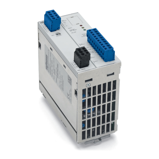
Device Description EPSITRON® 787-1675 Switched-Mode Power Supply with Integrated UPS Charger and Controller Pos : 18 /All e Seri en ( Allgemei ne Module)/Ü bers chriften für alle Serien/Gerätebeschr eibung/Ansic ht - Ü berschrift 2 @ 4\mod_1240984217343_21.doc @ 31958 @ 2 @ 1 View Pos : 19 /Serie 787 (EPSITRON)/Ger ätebesc hrei bung/Ansi cht/Ansic ht 787- 1675 @ 13\mod_1345791639239_21.doc @ 101944 @ @ 1 Figure 1: View of device... -
Page 15: Connectors
EPSITRON® Device Description 787-1675 Switched-Mode Power Supply with Integrated UPS Charger and Controller Pos : 21 /All e Seri en ( Allgemei ne Module)/Ü bers chriften für alle Serien/Gerätebeschr eibung/Ansc hlüs se - Übersc hrift 2 @ 4\mod_1240984262656_21.doc @ 31961 @ 2 @ 1 Connectors Pos : 22.1 /Serie 787 (EPSITRON)/Ger ätebesc hrei bung/Ans chl üss e/Ans chl üss e 787-1675 - Versorgung @ 13\mod_1347952219203_21.doc @ 102916 @ 3 @ 1 3.2.1... -
Page 16: Battery, Control And Signaling Contacts
Device Description EPSITRON® 787-1675 Switched-Mode Power Supply with Integrated UPS Charger and Controller 3.2.3 Battery, Control and Signaling Contacts Table 6: Connections – Battery, control and signaling contacts Designatio Function Battery connection 0 V Battery connection 24 V °C Signal line for "Bat. Control" °C Signal line for "Bat. -
Page 17: Display Elements
EPSITRON® Device Description 787-1675 Switched-Mode Power Supply with Integrated UPS Charger and Controller Display Elements Pos : 24 /Serie 787 (EPSITRON)/Ger ätebesc hrei bung/Anz eigeelemente/Anz eigeelemente 787- 1675 @ 13\mod_1346060933352_21.doc @ 101967 @ @ 1 The unit is equipped with three LEDs, which indicate the following statuses: Figure 6: Display elements Table 8: Legend for "Indicators"... -
Page 18: Operating Elements
Device Description EPSITRON® 787-1675 Switched-Mode Power Supply with Integrated UPS Charger and Controller Pos : 26 /All e Seri en ( Allgemei ne Module)/Ü bers chriften für alle Serien/Gerätebeschr eibung/Bedi enel emente - Ü bers chrift 2 @ 4\mod_1239191655456_21.doc @ 30439 @ 2 @ 1 Operating Elements Pos : 27 /Serie 787 (EPSITRON)/Ger ätebesc hrei bung/Bedienelemente/Bedi enel emente 787-1675 @ 13\mod_1346060971825_21.doc @ 101981 @ 33 @ 1 3.4.1... -
Page 19: Technical Data
EPSITRON® Device Description 787-1675 Switched-Mode Power Supply with Integrated UPS Charger and Controller Pos : 29 /All e Seri en ( Allgemei ne Module)/Ü bers chriften für alle Serien/Gerätebeschr eibung/Tec hnisc he Daten - Ü bers chrift 2 @ 3\mod_1232967587687_21.doc @ 26924 @ 2 @ 1 Technical Data Pos : 30 /Serie 787 (EPSITRON)/Ger ätebesc hrei bung/T ec hnisc he D aten/Tec hnisc he Daten 787-1675 @ 13\mod_1342438358691_21.doc @ 100320 @ 333443333 @ 1 3.5.1... -
Page 20: Technical Data "Output
Device Description EPSITRON® 787-1675 Switched-Mode Power Supply with Integrated UPS Charger and Controller 3.5.3 Technical Data "Output" Table 11: Technical data - "Output" Recovery stability maximum 35 VDC Overvoltage Protection 38 VDC Parallel connection of several modules yes, with a maximum of two modules decoupled from one another Series connection of several modules yes, without any restrictions... - Page 21 EPSITRON® Device Description 787-1675 Switched-Mode Power Supply with Integrated UPS Charger and Controller Table 13: Technical data for the output during Battery mode Switching of capacitive loads maximum 10000 µF Adjustable buffer time 1, 2, 3, 5, 10, 15 and 20 minutes; "PC mode";...
-
Page 22: Technical Data "Signaling
Data bits Stopbits Parity none Protocol On request Configuration Software 759-870 V2, from Version 2.5 (available free of charge at www.wago.com) ® Interface modules CAGE CLAMP , 734 Series; 0.08 mm … 0.5 mm ; AWG 28 … 20 Line length ≤... -
Page 23: Technical Data "Ambient Conditions
EPSITRON® Device Description 787-1675 Switched-Mode Power Supply with Integrated UPS Charger and Controller 3.5.6 Technical Data "Ambient Conditions" Table 16: Technical data - "Ambient conditions" Storage temperature -25 °C … +85 °C Ambient operating temperature -25 °C … +70 °C Derating -3 %/K (>... -
Page 24: Approvals
Device Description EPSITRON® 787-1675 Switched-Mode Power Supply with Integrated UPS Charger and Controller Pos : 32 /All e Seri en ( Allgemei ne Module)/Ü bers chriften für alle Serien/Gerätebeschr eibung/Zul ass ung en - Übersc hrift 2 @ 3\mod_1224055364109_21.doc @ 24030 @ 2 @ 1 Approvals Pos : 33 /Serie 787 (EPSITRON)/Ger ätebesc hrei bung/Z ulassungen/Z ulassungen U nterbr echungsfrei e Stromvers orgung 787- xxxx allgemein, ohne Variantenangabe - Ei nlei tun @ 13\mod_1347518988157_21.doc @ 102690 @ @ 1 The following approvals have been awarded to the uninterruptible power supply... -
Page 25: Standards And Guidelines
EPSITRON® Device Description 787-1675 Switched-Mode Power Supply with Integrated UPS Charger and Controller Pos : 36 /All e Seri en ( Allgemei ne Module)/Ü bers chriften für alle Serien/Gerätebeschr eibung/Nor men und Richtlini en - Übersc hrift 2 @ 4\mod_1242804031875_21.doc @ 33646 @ 2 @ 1 Standards and Guidelines Pos : 37 /Serie 787 (EPSITRON)/Ger ätebesc hrei bung/N ormen und Ric htli nien/N ormen und Ric htli nien U nterbrechungs freie Stromversorgung 787- xxxx, ohne Variantenangabe - Ei nl @ 13\mod_1347519108515_21.doc @ 102694 @ @ 1 The uninterruptible power supply system 787-1675 complies with the following... -
Page 26: Mounting
Mounting EPSITRON® 787-1675 Switched-Mode Power Supply with Integrated UPS Charger and Controller Pos : 44 /All e Seri en ( Allgemei ne Module)/Ü bers chriften für alle Serien/Monti eren - D emonti eren/M ontier en - Übersc hrift 1 @ 3\mod_1225446744750_21.doc @ 24900 @ 1 @ 1 Mounting Pos : 45 /Serie 787 (EPSITRON)/M ontier en/Montage 787- xxxx @ 11\mod_1317296048899_21.doc @ 80170 @ 22 @ 1 ®... -
Page 27: Connect Devices
EPSITRON® Connect Devices 787-1675 Switched-Mode Power Supply with Integrated UPS Charger and Controller Pos : 47 /All e Seri en ( Allgemei ne Module)/Ü bers chriften für alle Serien/Ansc hließ en/Geräte ansc hließ en - Ü bersc hrift 1 @ 3\mod_1234172889468_21.doc @ 27460 @ 1 @ 1 Connect Devices Pos : 48 /All e Seri en ( Allgemei ne Module)/Ü... -
Page 28: Function Description
Function Description EPSITRON® 787-1675 Switched-Mode Power Supply with Integrated UPS Charger and Controller Pos : 51 /All e Seri en ( Allgemei ne Module)/Ü bers chriften für alle Serien/Funktions besc hr eibung - Ü berschrift 1 @ 4\mod_1239025975389_21.doc @ 30003 @ 1 @ 1 Function Description Pos : 52 /Serie 787 (EPSITRON)/F unkti ons besc hrei bung/Ausl ösen von Lei tungssc hutzsc halter n 787-1675 @ 13\mod_1342614840028_21.doc @ 100547 @ 2 @ 1 Tripping of Circuit Breakers... -
Page 29: Signaling Via Leds
EPSITRON® Function Description 787-1675 Switched-Mode Power Supply with Integrated UPS Charger and Controller Pos : 54 /Serie 787 (EPSITRON)/F unkti ons besc hrei bung/Signalisier ung über LEDs 787-1675 @ 13\mod_1342616079771_21.doc @ 100550 @ 2 @ 1 Signaling via LEDs The table below contains all of the LED signals that can occur on the device: Table 19: Operating statuses, signaling and reactions. -
Page 30: Automatic Detection Of Battery Modules
Function Description EPSITRON® 787-1675 Switched-Mode Power Supply with Integrated UPS Charger and Controller Pos : 56 /Serie 787 (EPSITRON)/F unkti ons besc hrei bung/Batteriemodul e 787-1675 @ 13\mod_1342686258943_21.doc @ 100573 @ 2344 @ 1 Automatic Detection of Battery Modules The unit automatically detects 787-87x Series battery modules connected to the system, provided the "Bat. -
Page 31: Connecting A Battery Module From A Third-Party Manufacturer
EPSITRON® Function Description 787-1675 Switched-Mode Power Supply with Integrated UPS Charger and Controller 6.4.1.2 Connecting a Battery Module from a Third-Party Manufacturer Before connecting, check whether the battery module you wish to use is a rechargeable • lead cell battery, •... -
Page 32: Quality Test
Function Description EPSITRON® 787-1675 Switched-Mode Power Supply with Integrated UPS Charger and Controller If the unit determines negative results for the test, it is repeated again after only 30 seconds. The red LED lights up and the signal output "Bat. Alarm" is activated. 6.5.3 Quality Test The service life of batteries is limited and can be between 2 - 5 years, depending... -
Page 33: Switch-On Threshold For Battery Mode
Follow the information given in the Help function in the software to properly install the "759-870 V2" configuration software and use it for individually configuring your system. You can download the softare free of charge at www.wago.com. 6.6.1 Switch-On Threshold for Battery Mode Power supply is drawn from the battery when the output voltage drops below the set switch-on threshold. -
Page 34: Delay Time
Function Description EPSITRON® 787-1675 Switched-Mode Power Supply with Integrated UPS Charger and Controller Shut down PC: 1 – 600 seconds • PC idle (off) time: 1 – 60 seconds • The time sequence for the individual actions is permanently defined. 6.6.3.1 Delay Time The unit's output is not de-activated if power is restored within the set delay time. -
Page 35: Shut Down Pc
EPSITRON® Function Description 787-1675 Switched-Mode Power Supply with Integrated UPS Charger and Controller If the set delay time expires before power is restored, the output voltage and signal output are switched as shown in the flow chart below: Figure 13: Flow chart – "Input voltage not restored before set delay time expires." 6.6.3.2 Shut Down PC The signal output "Bat. -
Page 36: Deactivating The Battery Mode
Function Description EPSITRON® 787-1675 Switched-Mode Power Supply with Integrated UPS Charger and Controller Figure 14: Flow chart – "Input voltage not restored before the set delay time expires." 6.6.4 Deactivating the Battery Mode The Battery mode can be de-activated if the load connected to the system is not to be supplied from the battery module. -
Page 37: Recommended Battery Modules
EPSITRON® Function Description 787-1675 Switched-Mode Power Supply with Integrated UPS Charger and Controller 6.6.6 Recommended Battery Modules ® WAGO offers a battery module designed especially for EPSITRON devices. These are listed below: Table 20: Recommended battery modules Battery Capacity Maximum... -
Page 38: List Of Figures
List of Figures EPSITRON® 787-1675 Switched-Mode Power Supply with Integrated UPS Charger and Controller Pos : 60 /D okumentation allgemei n/Verz eic hniss e/Abbil dungs verz eic hnis - Übersc hrift oG und Verz eichnis @ 3\mod_1219222916765_21.doc @ 21080 @ @ 1 List of Figures Figure 1: View of device .................. -
Page 39: List Of Tables
EPSITRON® List of Tables 787-1675 Switched-Mode Power Supply with Integrated UPS Charger and Controller Pos : 62 /D okumentation allgemei n/Verz eic hniss e/T abell enverz eichnis - Ü berschrift oG - und Verz eichnis @ 3\mod_1219222958703_21.doc @ 21084 @ @ 1 List of Tables Table 1: Number notation .................. - Page 40 Pos : 64 /D okumentation allgemei n/Einband/Einband H andbuc h - R üc kseite @ 9\mod_1285229376516_21.doc @ 64944 @ @ 1 WAGO Kontakttechnik GmbH & Co. KG Postfach 2880 • D-32385 Minden Hansastraße 27 • D-32423 Minden Phone: +49/5 71/8 87 – 0 Fax: +49/5 71/8 87 –...
Need help?
Do you have a question about the EPSITRON 787-1675 and is the answer not in the manual?
Questions and answers