Table of Contents
Advertisement
Quick Links
INSTALLATION AND OPERATION INSTRUCTIONS FOR
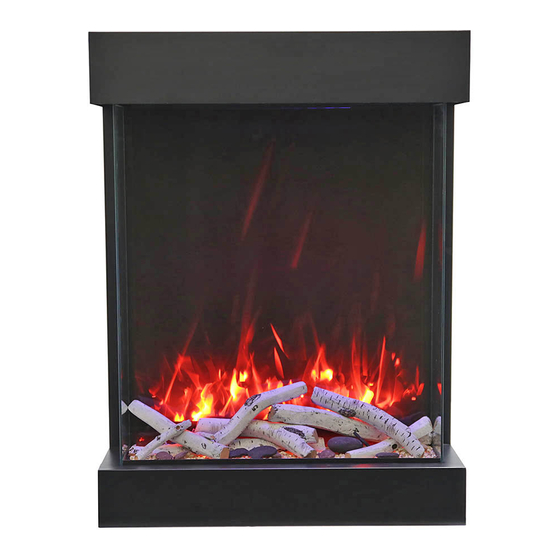
2939-TRU-VIEW-XL
SAFETY INFORMATION
WARNING
For your safety, always comply with all
warnings and safety instructions
contained in this manual to prevent
personal injury or property damage.
Do not store or use gasoline or other flammable vapors
and liquids in the vicinity of this appliance.
INSTALLER: LEAVE OWNER'S MANUAL WITH THE APPLIANCE.
CONSUMER: RETAIN OWNER'S MANUAL FOR FUTURE REFERENCE.
Advertisement
Table of Contents

Related Manuals for Amantii 2939-TRU-VIEW-XL


Summary of Contents for Amantii 2939-TRU-VIEW-XL
- Page 1 INSTALLATION AND OPERATION INSTRUCTIONS FOR 2939-TRU-VIEW-XL SAFETY INFORMATION WARNING For your safety, always comply with all warnings and safety instructions contained in this manual to prevent personal injury or property damage. Do not store or use gasoline or other flammable vapors and liquids in the vicinity of this appliance.
-
Page 2: Table Of Contents
Please read and carefully follow all of the instruction found in this manual. Please pay special attention to the safety instructions provided in this manual. The instructions included here will assure that you have many years of dependable and enjoyable service from your Amantii product. Table of Contents IMPORTANT INSTRUCTIONS .......................... -
Page 3: Important Instructions
IMPORTANT INSTRUCTIONS 1. Do not operate appliance before reading and understanding operating instructions. Failure to operate appliance according to operating instructions could cause fire or injury. 2. Keep combustible materials such as furniture, pillows, bedding, clothing, curtains and paper at least 3 ft from the front, sides and rear of the heater. -
Page 4: Unpacking And Testing Appliance
UNPACKING AND TESTING APPLIANCE Carefully remove the appliance from the box. Prior to installing the appliance, test to make sure the appliance operates properly by plugging the power supply cord into a conveniently located 120 Volt grounded outlet. Test all aspects of its operation (manual switches, remote and heater) to make sure all components operate correctly. -
Page 5: 2939-Tru-View-Xl
2939-TRU-VIEW-XL This appliance has been tested in Description ELECTRIC FIREPLACE accordance with the UL Standard 2021 Voltage 120V AC 60Hz for fixed and location dedicated Watts 1500W Max electric room appliances in the United NO HEATER States and Canada. If you need... - Page 6 2939-TRU-VIEW-XL This appliance has been tested in Description ELECTRIC FIREPLACE accordance with the UL Standard 2021 Voltage 120V AC 60Hz for fixed and location dedicated Watts 1500W Max electric room appliances in the United NO HEATER States and Canada. If you need...
-
Page 7: Installation Wall-Mount
INSTALLATION WALL-MOUNT NOTE: Due to variables in installation location and materials, it is highly recommended that you consult your local builder before you install this appliance. 1. Select a location that is not prone to moisture and is located at least 0.91 m or 3 feet away from combustible materials such as curtains or drapes, furniture, bedding, paper, etc. -
Page 8: Installation Built-In
INSTALLATION BUILT-IN 1. Carefully remove the appliance from the box. Prior to installation, test to make sure the fireplace operates properly. 2. Get the bracket and framing from the parts kit, and screw them to the fireplace as shows below. bracket framing framing... - Page 9 3. Use the brackets you used in Step 2 to fix the completed mantel to the fireplace. 4. After checking that the fireplace operates properly, you may now decorate the surrounding area with a finish of your choice.
-
Page 10: Installation Outdoor
INSTALLATION OUTDOOR 2939-TRU-VIEW-XL electric fireplaces are suitable for installation in outdoor areas protected from direct water impingement. In addition to maintaining the listed mantel and combustibles clearances, a rain protection overhang factor of 1/2 shall be constructed to the front and to each side of the installed appliance. -
Page 11: Hard- Wire Installation
HARD- WIRE INSTALLATION Turn off the appliance completely and let cool before servicing. Only a qualified Turn off the appliance completely and let cool before servicing. Only a qualified Turn off the appliance completely and let cool before servicing. Only a qualified technician should service and repair this electric appliance. -
Page 12: Media Options
MEDIA OPTIONS Your fireplace ships with a 10 piece Birch Log STEP 3: Remove the front glass panel to Set, two (2) bags of Smoke Glass, one (1) bag decorate your fireplace. Pour the decorative of Black Vermiculite and one (1) bag of White media into the tray. -
Page 13: Operation
OPERATION The fireplace can be operated by the switches located on the left front of the fireplace unit or by by the switches located on the left front of the fireplace unit or by by the switches located on the left front of the fireplace unit or by remote control (included). -
Page 14: Remote Control Operation
REMOTE CONTROL OPERATION REMOTE CONTROL OPERATION For remote to function make sure the heater is plugged in and main power switch located on the For remote to function make sure the heater is plugged in and main power switch located on the For remote to function make sure the heater is plugged in and main power switch located on the bottom left hand side is at position I. -
Page 15: Installing Wall Thermostat
INSTALLING WALL THERMOSTAT WALL THERMOSTAT WIRING DIAGRAMS Wire the wall thermostat prior to installing the fireplace. WALL THERMOSTAT WIRING (24 VAC) Install Wall Thermostat per instructions provided with kit and per the following information: 1. Turn off circuit breaker. 2. Remove cover plate located on the left side of appliance. Pull the wire out and cut the inside thermostat. -
Page 16: Replacement Parts
REPLACEMENT PARTS This list contains replacement parts PART NUMBER DESCRIPTION QTY. 10701373 FRONT CLEAR GLASS (MIDDLE) 10201505 ADJUSTABLE SCREW 3123010 FIXER FOR FRONT GLASS PANEL 10701374 SIDE GLASS PANEL 10702242 VISUAL GLASS 10702243 BOTTOM GLASS 602082 BLOWER AND HEATER ASSEMBLY 601036 CONTROL PANEL 10104002... - Page 17 EXPLODED VIEW...
-
Page 18: Wiring Diagram
Wiring Diagram... -
Page 19: Troubleshooting
TROUBLE SHOOTING PROBLEM POSSIBLE CAUSE SOLUTION Dim or no flame Flame LED’s are burnt out. Inspect the LED’s and replace them if necessary. Back black cloth is falling off Change a flicker and back black cloth. and rolled up in the flicker. Ember Ember LED’s are burnt out Inspect the ember bed LED’s and... -
Page 20: Service History
SERVICE HISTORY This heater must be serviced annually depending on usage. Date Dealer Service technician Service Performed Special Concerns Name Name NOTES:... -
Page 21: Warranty
Amantii warrants such products to be free from defects in material and workmanship for a period of two (2) years from the date of the first purchase of such products. The limited two (2) year warranty period for products also applies to any implied warranties that may exist under applicable law. Some...
Need help?
Do you have a question about the 2939-TRU-VIEW-XL and is the answer not in the manual?
Questions and answers