
Related Manuals for Motorola SRX 2200 Model 3.5


Summary of Contents for Motorola SRX 2200 Model 3.5
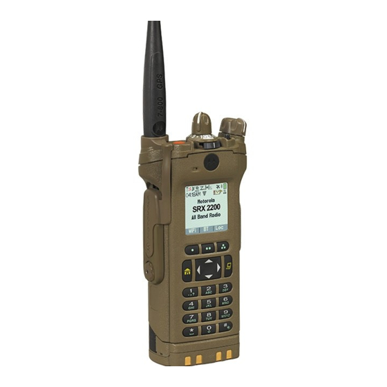
- Page 1 APX TWO-WAY RADIOS SRX 2200 Model 3.5 USER GUIDE DEC 2018 *68012005051* 2018 Motorola Solutions, Inc. All rights reserved © 68012005051-FK...
-
Page 2: Table Of Contents
English Contents Additional Performance Enhancement....31 ASTRO 25 Enhanced Data.....31 Dynamic System Resilience (DSR)..31 Declaration of Conformity..........12 CrossTalk Prevention......31 Important Safety Information........14 Encrypted Integrated Data (EID).... 32 Notice to Users (FCC and Industry Canada)....15 SecureNet..........32 Software Version............16 P25 Digital Vehicular Repeater System Computer Software Copyrights........ - Page 3 English Radio Parts and Controls........42 LED Indicator.............63 Programmable Features........44 Intelligent Lighting Indicators......64 Assignable Radio Functions....44 Alert Tones ............66 Assignable Settings or Utility Functions..47 Phone Call Displays and Alerts......70 Accessing the Preprogrammed Functions..48 Display Color Change On Channel....71 Menu Select Buttons.......48 HAZLOC Battery Type Detection......
- Page 4 English Methods to Make a Radio Call......79 Making a Priority Dispatch Calls..... 88 Making a Talkgroup Call ......79 Responding to the Dynamic Regrouping Feature (Trunking Only)..88 Making a Private Call (Trunking Only)..80 Requesting a Reprogram Making an Enhanced Private Call (Trunking Only)......
- Page 5 English Adding a Contact to a Call List....97 Receiving a Call Alert Page....105 Removing a Contact from a Call List..98 Sending a Call Alert Page.....106 Methods of Contact Editing in a Call Quick Call II (ASTRO P25 Digital Trunking List............
- Page 6 English Sending and Receiving Sending a Quick Text Message.... 127 Emergency Find Me Beacon..116 Priority Status and Request Reply of a Man Down............116 New Text Message....... 128 Pre-Alert Timer........118 Appending a Priority Status to a Text Message......128 Post-Alert Timer........
- Page 7 English Deleting a Text Message... 135 Requesting an Over-the-Air Rekey (ASTRO Conventional Deleting All Text Messages..135 Only).......... 147 ASTRO 25 Advanced Messaging Solution..136 MDC Over-the-Air Rekeying System Setup for ASTRO Advanced Page...........147 Messaging Solution......137 Infinite UKEK Retention..... 147 Two-Factor Authentication....
- Page 8 Deleting a Single Saved Waypoint..161 Turning Off the Bluetooth......170 Deleting All Saved Waypoints....161 Re-Pair Timer........171 Measuring the Distance and Bearing from a Saved Waypoint......162 Bluetooth Drop Timer......172 Location Feature in Emergency Mode.. 162 Pairing with Low Frequency-Motorola Proximity Pairing (LF-MPP) Feature..173...
- Page 9 English Radio Indications of Lost Bluetooth Clearing All Bluetooth Devices Connection..........174 Information..........182 Standard Pairing Feature......174 Editing the Bluetooth Friendly Name..183 Searching and Pairing the Responder Alert Sensors......184 Bluetooth Device......175 Holster Sensor......184 Turning On Bluetooth Visibility... 176 Weapon Fired Sensor....185 Receiving Pairing Request from Vest Pierced Sensor....
- Page 10 English Stopping SSA Notification of a Single Setting Up the Radio Display and Site by Manual Entry......193 Visual Indicators to Suit Night Vision Goggles..........203 Stopping SSA Notification of All Sites...194 Locking and Unlocking the Keypad and Stopping SSA Notification of All Controls..........
- Page 11 Chapter 5: Glossary........... 224 General Radio Information....214 Chapter 6: Limited Warranty........231 Accessing the Radio Information ........... 214 MOTOROLA SOLUTIONS COMMUNICATION PRODUCTS....231 Viewing the IP Information..215 I. WHAT THIS WARRANTY COVERS AND Viewing the Control FOR HOW LONG:........... 231 Assignments......
-
Page 12: Declaration Of Conformity
This declaration is applicable to your radio only if your radio is labeled with the FCC logo shown below. Declaration of Conformity Per FCC CFR 47 Part 2 Section 2.1077(a) Responsible Party Name: Motorola Solutions, Inc. Address: 1303 East Algonquin Road, Schaumburg, IL 60196-1078, U.S.A. Phone Number: 1-800-927-2744 Hereby declares that the product:... - Page 13 English As a personal computer peripheral, this device complies with Part 15 of the FCC Rules. Operation is subject to the following two conditions: 1 This device may not cause harmful interference, and 2 This device must accept any interference received, including interference that may cause undesired operation. NOTICE: This equipment has been tested and found to comply with the limits for a Class B digital device, pursuant to part 15 of the FCC Rules and Industry Canada license-exempt RSS standard.
-
Page 14: Important Safety Information
RF energy awareness and control for Compliance with applicable standards and Regulations. For a list of Motorola Solutions-approved antennas, batteries, and other accessories, visit the following website: http://www.motorolasolutions.com Under Industry Canada regulations, this radio transmitter... -
Page 15: Notice To Users (Fcc And Industry Canada)
• This device must accept any interference received, including interference that may cause undesired operation. • Changes or modifications made to this device, not expressly approved by Motorola Solutions, could void the authority of the user to operate this equipment. -
Page 16: Software Version
English Software Version All the features described in the following sections are supported by the software version R19.00.00 or later. Accessing the Radio Information on page 214 determine the software version of your radio. Check with your dealer or system administrator for more details of all the features supported. -
Page 17: Computer Software Copyrights
English Computer Software Copyrights The Motorola Solutions products described in this manual may include copyrighted Motorola Solutions computer programs stored in semiconductor memories or other media. Laws in the United States and other countries preserve for Motorola Solutions certain exclusive rights for... -
Page 18: Documentation Copyrights
No duplication or distribution of this document or any portion thereof shall take place without the express written permission of Motorola Solutions. No part of this manual may be reproduced, distributed, or transmitted in any form or by any means, electronic or mechanical, for any purpose without the express written permission of Motorola Solutions. -
Page 19: Disclaimer
The information in this document is carefully examined, and is believed to be entirely reliable. However, no responsibility is assumed for inaccuracies. Furthermore, Motorola Solutions reserves the right to make changes to any products herein to improve readability, function, or design. Motorola Solutions does not assume any liability arising out of the applications or use of any product or circuit described herein;... -
Page 20: Getting Started
English Getting Started NOTICE: An operational procedure, practice, or condition and so on, which is essential to emphasize. How to Use This Guide This User Guide covers the basic operation of the APX The following special notations identify certain items. Portables . -
Page 21: Radio Maintenance
English Radio Maintenance CAUTION: • Your radio casting has a vent port that allows for This chapter covers the radio and battery care. pressure equalization in the radio. Never poke this vent with any objects, such as needles, Radio Care tweezers, or screwdrivers.This could create leak paths into the radio and the radio submergibility Proper radio usage and care assures efficient operation... - Page 22 Motorola Solutions details connector/radio interface. Rinse and dry the area the disassembly, test, and reassembly...
-
Page 23: Cleaning Your Radio
English the radio. Any radio maintenance should be Cleaning Your Radio performed only by a qualified radio technician. CAUTION: • CAUTION: Do not use solvents to clean your radio as most Do not use the radio without an chemicals may permanently damage the radio accessory connector or a dust cover in housing and textures. -
Page 24: Preparation For Washing The Radio And Parts
English Preparation for Washing the Radio and Washing The Radio Parts 1 Submerge the radio (with battery attached) You can detach the battery and Universal Connector Cover completely into the tap water while shaking it for of the radio and have them and the radio brushed and approximately 20 seconds. - Page 25 English c Slide the Secure Switch back and forth twice. Dip the radio into the water one more time. 4 Lightly scrub the plastic area (front, back, bottom, top and side planes) of the radio with the small brush.Take extra care around the Speaker Grill and 3 Dip the radio completely into the detergent solution Microphone port openings.
- Page 26 English 5 Use the toothbrush to lightly brush the gaps at the base of the knobs and around the switches. Take extra care around the Speaker Grill and Microphone port openings. 8 Shake off excess water and pat dry the radio with a dry towel.
- Page 27 English Washing the Battery 1 Rinse the battery under running water to remove any excess debris. 5 Rinse the battery under running water to remove any excess detergent. Washing the Universal Connector Cover 2 Using the small brush dipped in the detergent solution, lightly scrub the front, botom and sides of 1 Dip the universal connector cover into tap water the battery.
-
Page 28: Radio Service And Repair
4 Rinse the cover under running waer to wash off the detergent. 5 Pat dry with a towel. Radio Service and Repair Proper repair and maintenance procedures will assure efficient operation and long life for this product. A Motorola Solutions maintenance agreement will provide expert... -
Page 29: Cleaning The External Surface Of The Radio
3 Dry the radio thoroughly with a soft, lint-free cloth. in perfect operating condition. A nationwide service organization is provided by Motorola Battery Care Solutions to support maintenance services. Through its... - Page 30 English Fuel Gauge Icons Gauge Battery Charge 26% to 50% A blinking fuel gauge icon ( ) is displayed only when the battery voltage drops to low level. In this case, replace the battery with a fully charged one. Top Display: Gauge Battery Charge 76% to 100% full...
-
Page 31: Battery Recycling And Disposal
Battery Recycling and Disposal improve data channel efficiency and enable denser network traffic. In the U.S. and Canada, Motorola Solutions participates in the nationwide Call2Recycle program for battery collection Dynamic System Resilience (DSR) and recycling. Many retailers and dealers participate in this program. -
Page 32: Encrypted Integrated Data (Eid)
SecureNet allows user to perform secured communications to operate on only the subset of talkgroups that are on an Analog or Motorola Data Communication (MDC) relevant to the users rather than all talkgroups on the channel. The MDC Over-the-Air Rekeying (OTAR) feature channel. -
Page 33: What Your Dealer/System Administrator Can Tell You
English What Your Dealer/System Administrator Can Tell You Check with your dealer or system administrator for the correct radio settings, if the radio is to be operated in extreme temperatures (less than -30 °C or more than +60 °C). You can consult your dealer or system administrator about the following: •... -
Page 34: Preparing Your Radio For Use
This section provides simple instructions to prepare your To charge the battery, place the battery (with or radio for use. without the radio) in a Motorola Solutions-approved charger. Charging the Battery The LED on the charger indicates the charging progress;... - Page 35 Solutions battery upon powering up, charging, or removing from the charger. This feature is applicable for IMPRES and Non-IMPRES battery. When the radio is attached with the non-Motorola Solutions battery, a tone sounds, display shows Unknown Battry temporarily and battery indicator is not shown in the radio display.
-
Page 36: Attaching The Antenna
English 2 Turn the antenna clockwise to attach to the radio. 3 To remove the antenna, turn the antenna counterclockwise. NOTICE: When removing the antenna, ensure that the radio is turned off. Attaching the Antenna Ensure the radio is turned off before attaching the antenna. 1 Set the antenna in the receptacle. -
Page 37: Removing And Attaching The Accessory Connector Cover
English Removing and Attaching the Accessory Connector Cover The accessory connector is on the antenna side of the radio. It is used to connect accessories to the radio. NOTICE: To prevent damage to the connector, shield it with the connector cover when not in use. 1 To remove the accessory connector cover, rotate the thumbscrew counterclockwise until it disengages... -
Page 38: Using The Carry Holder
English 6 Once in place, tighten by rotating the thumbscrew clockwise by hand. Using the Carry Holder 1 Position the radio within the carry holder with the main speaker facing outward. 3 To remove the radio from the carry holder, place the tip of your fingers on the ledge of the carry holder. -
Page 39: Turning On The Radio
English 4 Push at the bottom of the radio until the radio is released from it. Turning On the Radio 1 Rotate the On/Off/Volume Control Knob clockwise until you hear a click. -
Page 40: Adjusting The Volume
English 2 To turn off the radio, rotate the On/Off/Volume Control Knob counterclockwise until you hear a click. • If the power-up test is successful, you see a splash screen on the radio display, followed by the Home screen and the Codeplug Alias. •... - Page 41 English 2 To decrease the volume, rotate this knob counterclockwise.
-
Page 42: Identifying Radio Controls
English Identifying Radio Controls Radio Parts and Controls This chapter explains the buttons and functions to control the radio. - Page 43 English Microphone Accessory Connector Home Button 4–Way Navigation Button Battery Latch Keypad Data Feature Button Menu Select Buttons Main Display 3–Position A/B/C Switch 2–Position Concentric Switch On/Off/Volume Control Knob Top Side (Select) Button Push-to-Talk (PTT) Button Side Button 1 Antenna Side Button 2 Battery Top (Orange) Button...
-
Page 44: Programmable Features
English Assignable Radio Functions Bluetooth Pairing Location Indicator Main Speaker Bluetooth On/Off Allows you to turn on/off the Bluetooth. Microphone Bluetooth Configuration Top Display Allows you to access to the Bluetooth menu. 16-Position Select Knob Bluetooth Audio Reroute Allows you to toggle the audio route between radio Programmable Features speaker or Remote Speaker Microphone and Bluetooth headset. - Page 45 English Call Alert Location Allows the radio to function like a pager, or to verify if a Determines the current location (latitude, longitude, time radio is active on the system. and date), and also the distance and bearing to another location or turns the GPS functionality on or off for all Call Response locations.
- Page 46 English Nuisance Delete Radio Profiles Temporarily removes an unwanted channel, except for Allows easy access to a set of preprogrammed visual priority channels or the designated transmit channel and audio settings of the radio. from the scan list. Recent Calls One Touch 1–4 Allows easy access to the list of calls recently received Launches a specific feature with one single button-...
-
Page 47: Assignable Settings Or Utility Functions
English Secure Transmission Select (Conventional and Text Messaging Service (TMS) Trunking) Selects the text messaging menu. Toggles the Secure Transmission On or Off when the TMS Quick Text Secure/Clear Strapping fields is set to Select for the Selects a predefined message. current channel and when the radio is model/option User capable. -
Page 48: Accessing The Preprogrammed Functions
English Light/Flip • Use the Menu Select and Navigation buttons. Press the button to toggle the display backlight on or off; press and hold the button to reverse the content of the top display. TX Power Level Toggles transmit power level between high and low. Voice Announcement Audibly indicates the current feature mode, Zone or Channel the user has just assigned. -
Page 49: Home Button
English Use the Menu Select button to access the menu entry of • Press and release one of the buttons to scroll from one your radio feature. Your radio may be preprogrammed entry to the next one. differently from the following example, but the steps for •... -
Page 50: Keypad Characters - Uppercase Mode
English Keypad Characters – Uppercase Mode Number of Times Key is Pressed & “ ‘ Toggle between mixed case mode, uppercase mode and lowercase mode. Space... -
Page 51: Keypad Characters - Lowercase Mode
English Number of Times Key is Pressed Toggle between numeric and letter mode. Keypad Characters – Lowercase Mode Number of Times Key is Pressed & “ ‘... -
Page 52: Keypad Characters - Numeric Mode
English Number of Times Key is Pressed Toggle between mixed case mode, uppercase mode and lowercase mode. Space Toggle between numeric and letter mode. Keypad Characters – Numeric Mode Number of Times Key is Pressed & “ ‘... - Page 53 English Number of Times Key is Pressed Space Toggle between numeric and letter mode.
-
Page 54: Keypad Characters - Hexadecimal Mode
English Keypad Characters – Hexadecimal Mode Number of Times Key is Pressed Not applicable... -
Page 55: Push-To-Talk (Ptt) Button
English Number of Times Key is Pressed Not applicable Push-To-Talk (PTT) Button Press and hold down PTT button to talk. Release the PTT button to listen. The microphone is activated when the PTT button is pressed. • While a call is not in progress, the PTT button is used to make a new call. -
Page 56: Identifying Status Indicators
English Identifying Status Indicators Transmitting Radio is transmitting a call or data. This chapter explains the status indicators used in the Top Dis- radio. play: Status Icons Call Received The 130 x 130 pixel front liquid crystal display (LCD) of Radio has received an Individual Call. - Page 57 English Roaming The radio has roamed to and is currently The feature is enabled. Voice muting of registered to a foreign system. the affiliated trunking talkgroup or se- Top Dis- lected conventional channel is activated. play: The feature is disabled. Voice muting of the affiliated trunking talkgroup or se- Direct lected conventional channel is deactivat-...
- Page 58 English Blinking dot Radio detects activity on channel desig- Radio is in Zone 2. nated as Priority-One. Steady dot Radio is in Zone 3. Radio detects activity on channel desig- Top Dis- Basic Zone Bank 2 nated as Priority-Two. play: Top Dis- View/Program Mode Radio is in Zone 4.
- Page 59 English Contains Zone 70, Zone 71, and Zone Feature is enabled and signal is availa- ble. Contains Zone 73, Zone 74, and Zone Feature is disabled. Blinking Feature is enabled, but no signal is Secure Operation available. Top Dis- Secure operation. User Login Indicator (IP Packet Data) play: Clear operation.
- Page 60 English Data Activity Lowercase Predictive Data activity is present. Indicates that the text entry is currently in lowercase and with predicted words Hexadecimal shown at the bottom of the screen. Indicates that the text entry is currently in hexadecimal mode. Mixedcase Predictive Indicates that the text entry is currently Numeric...
-
Page 61: Text Messaging Service (Tms) Indicators
English Message Sent The text message is sent successfully. The radio Wi-Fi ® network is connected. Message Unsent The number of bars displayed represents the signal strength of the Wi-Fi signal. The text message cannot be sent. Unread Message Text Messaging Service (TMS) •... -
Page 62: Tms Menu Options
English TMS Menu Options Inbox folder, the icon is displayed as the icon on the left column. The following menu options appear on the radio display when you send and receive text messages. Priority Status • The “Priority” feature is toggled on before the message is sent. -
Page 63: Call Type Icons
English Call Type Icons Outgoing call or data. The following icons appear on the radio main display, when Incoming emergency call. you make or receive a call, or view selected call lists, to indicate the different call types associated with an alias or LED Indicator Radio number. -
Page 64: Intelligent Lighting Indicators
English Rapidly blinking red Rapidly blinking green Radio has failed the self test upon powering up or Radio is on a Priority-One channel while in the Scan encountered a fatal error. List Programming mode. Solid yellow (Conventional Only) NOTICE: Channel is busy. No LED indication when the radio receives a clear (non-secured) transmission in trunking Mode. - Page 65 English NOTICE: This feature must be preprogrammed by a qualified radio technician. Backlight and Bar Notification When Color Orange Emergency Alerts The radio initiates an emergency alarm or call. The radio receives an emergency alarm or call. The radio initiates the Man Down Post-Alert timer. Green Call Alerts The radio receives a private call.
-
Page 66: Alert Tones
English Alert Tones Your radio uses alert tones to inform you of the condition of your radio. The following table lists these tones and when they occur. You Hear Tone Name Heard Short, Low- Radio Self Test Fail When radio fails its power-up self test. Pitched Tone Reject When an unauthorized request is made. - Page 67 English You Hear Tone Name Heard Out of Range (When PTT button is pressed) the radio is out of range of the sys- tem. Invalid Mode When radio is on an unpreprogrammed channel. A Group of Busy When system is busy. Low-Pitched Tones Short, Medi-...
- Page 68 English You Hear Tone Name Heard Console Acknowledge When status, emergency alarm, or reprogram request ACK is re- ceived. Received Individual Call When Call Alert or Private Call is received. Call Alert Sent When Call Alert is received by the target radio. Site Trunking When a SmartZone trunking system fails.
- Page 69 English You Hear Tone Name Heard Unique, High- Priority Status When a priority message is received. Pitched Chirp Incremental- Bluetooth Paired When Bluetooth accessory is paired with the radio. Pitched Tone Bluetooth Connected When Bluetooth accessory is connected to the radio. Decremental- Bluetooth Unpaired When Bluetooth accessory is unpaired from the radio.
-
Page 70: Phone Call Displays And Alerts
English Phone Call Displays and Alerts The following phone call displays and alerts appears on the radio display when you make and receive Phone calls. The radio also uses alert tones to indicate the current status. You Hear You See When Notes A Long Tone... -
Page 71: Display Color Change On Channel
English NOTICE: You have the option of sending additional digits (overdial), such as an extension number, credit card, or PIN numbers to the phone system. If the radio is preprogrammed for live overdial, every digit entered after the call is connected, is sent to the phone system. - Page 72 English • LED blinks RED continuously NOTICE: The radio does not display any indication when the radio is connected to the charger, when the radio and battery match, or when the radio certification type is configured as "None" in Customer Programming Software (CPS). This feature is enabled through CPS configuration.
-
Page 73: Chapter 1: General Radio Operation
English General Radio Operation • Select a zone using the radio menu Zone: or to Zone and press the Menu Select button This chapter explains the general radio operations in your directly below Zone. radio. to the required zone, or use the keypad to enter the zone number. -
Page 74: Selecting A Radio Channel
English Selecting a Radio Channel d. Press the Menu Select button directly below Sel to confirm the selected channel. e. Press the PTT button to transmit on the displayed A channel is a group of radio characteristics, such as zone channel. transmit/receive frequency pairs. -
Page 75: Mode Select Feature
English Your radio prompts the first found channel if a match is • If the radio is triggered to search for an empty entry, the found. display shows Invalid entry. Repeat step 2 to search again. 1 Perform one of the following actions: •... -
Page 76: Saving A Zone And A Channel To A Softkey
English Saving a Zone and a Channel to a Saving a Zone and a Channel to a Softkey Button Five softkeys are available for you to save the frequently You can save the frequently used zone and channel to the used zone and channel. -
Page 77: Receiving And Responding To A Talkgroup Call
English The radio shows different indicators based on the system • For Trunking system, the display shows the caller alias the radio is configured. or ID. • The LED lights up solid red while the radio is 1 Hold the radio vertically 1 to 2 inches (2.5 to 5.0 cm) transmitting. -
Page 78: Receiving And Responding To A Telephone Call (Trunking Only)
English NOTICE: 3 Press or the Call Response button to hang up With the inactivity timer enabled (optional), when and return to the Home screen. there is no response from the receiving radio, the calling radio exits the call with Menu Inactive Exit See also Making a Private Call (Trunking Only) on page tone after the timer expires. -
Page 79: Methods To Make A Radio Call
English Making a Talkgroup Call 2 Press and hold the PTT button to talk. Release the PTT button to listen. To make a call to a group of users, your radio must be configured as part of that talkgroup. 3 Press or the Call Response button to hang up and return to the Home screen. -
Page 80: Making A Private Call (Trunking Only)
English Making a Private Call (Trunking Only) • to the required ID. • Use the keypad to enter the required ID. Your radio must be preprogrammed for you to use this feature. 3 Press the PTT button to initiate the Private Call. This feature allows you to send an individual Call Alert or The display shows Calling... - Page 81 English This feature allows you to send an individual Call Alert • Use the keypad to enter the required ID. Page if there is no answer from the target radio. See Sending a Call Alert Page on page 106 for more 3 Press the PTT button to initiate the Private Call.
-
Page 82: Making A Telephone Call (Trunking Only)
English Making a Telephone Call (Trunking • Use the keypad to enter the required phone number. Only) 3 Press the PTT button to dial the phone number. This feature allows you to make calls similar to standard phone calls to a mobile or landline phone. 4 Hold the radio vertically 1 to 2 inches (2.5 to 5.0 cm) from your mouth. -
Page 83: Monitor Feature
English The Direct or “talkaround operation” allows you to bypass Digital technology quiets the transmission by removing the the repeater and connect directly to another radio. The noise from the signal and allows only the clear voice or transmit and receive frequencies are the same. data information to be heard. -
Page 84: Monitoring Conventional Mode
English c. Press and hold the PTT button to transmit. Monitoring Conventional Mode The LED lights up solid red. ® Your radio may be preprogrammed to receive Private-Line (PL) calls. d. Release the PTT button to receive (listen). The Carrier Squelch indicator appears on the 1 Momentarily press the Monitor button to listen for display when you monitor a channel using the activity. -
Page 85: Chapter 2: Advanced Features
English Advanced Features • The LED blinks solid green once to indicate the transmitting radio is pending to receive signal. The speaker unmutes. This chapter explains the operations of the features available in your radio. 1 Hold the radio vertically 1 to 2 inches (2.5 to 5.0 cm) from your mouth. -
Page 86: Talkgroup Call Feature (Conventional Operation Only)
English Talkgroup Call Feature (Conventional 2 To select the required ID, perform one of the following actions: Operation Only) • Press the Menu Select button directly below This feature allows you to define a group of conventional Cnts to scroll through and select the required ID. system users so that they can share the use of a •... -
Page 87: Sending A Status Call
English • to the required Talkgroup. NOTICE: The radio automatically exits the feature, if the • Use the keypad to enter the number of the feature inactivity timer is enabled. You will hear the corresponding Talkgroup in the list. Menu Inactive Exit Tone upon feature exit. 3 Press the Menu Select button directly below Sel to 1 Perform one of the following actions: save the currently selected Talkgroup and return to... -
Page 88: Making A Priority Dispatch Calls
English If no acknowledgment is received, you hear a low- 1 Press the preprogrammed Priority Dispatch button. pitched tone and the display shows No A tone sounds and the radio enters Priority Dispatch acknowledge. mode. The radio exits this mode when the Priority Dispatch Time Out Timer expires. -
Page 89: Requesting A Reprogram (Trunking Only)
English You will not notice whether your radio has this feature • Press the preprogrammed Reprogram Request enabled until a dynamic regrouping command is sent by button to send reprogram request to the the dispatcher. dispatcher. NOTICE: • or to Rpgm then press the Menu Select button If you try to access a zone or channel that has been directly below Rpgm to send reprogram request to reserved by the dispatcher as a dynamically... -
Page 90: Dynamic Zone Programming (Dzp)
English channel, once the user has selected the dynamic- Entering the Dynamic Zone to Select a regrouping position. Dynamic Channel Select Disabled Select-disabled radios cannot change channels while or to Zone then press the Menu Select button dynamically regrouped. The dispatcher has forced the directly below Zone. -
Page 91: Saving A Channel In The Dynamic Zone From List Selection
English Saving a Channel in the Dynamic Zone to the required channel. Press the Menu from List Selection Select button directly below Sel . The display shows Channel updated. The radio must be in Dynamic Zone in order to perform this operation. -
Page 92: Deleting A Channel In The Dynamic Zone
English Deleting a Channel in the Dynamic Zone to Channel Name then press the Menu Select button directly below Sel . The radio must be in Dynamic Zone in order to perform this The display shows a blinking cursor on the Channel operation. -
Page 93: Zone To Zone Cloning
English Zone to Zone Cloning Select button directly below Ok and the radio returns to the previous screen. Zone to Zone Cloning clones conventional zones from one Once connected, the zone clone status is displayed radio to another. This feature allows you to select the clone on the right. -
Page 94: Contacts
English Contacts 5 Press the Menu Select button directly below Clon to begin cloning. This feature provides “address-book” capabilities on your The radio displays Enter password if the protected radio. Each entry corresponds to an alias (name) or ID target zone is selected. (number) that you use to initiate a call. -
Page 95: Making A Private Call From Contacts
English Your radio also supports a maximum of 50 call lists. Each • or to scroll through the available IDs for the list can store up to 100 IDs (numbers). selected subscriber alias and proceed to step NOTICE: to Call and press the Menu Select button Your radio is preprogrammed with a number of directly below Sel. -
Page 96: Adding A New Contact Entry
English Adding a New Contact Entry to Number 1 and press the Menu Select button directly below Edit . or to Cnts and press the Menu Select button The display shows Edit Num 1 and a blinking directly below Cnts . cursor appears. -
Page 97: Deleting A Contact Entry
English 9 Press the Menu Select button directly below Done 4 Select the Menu Select button directly below Yes to once you have finished. delete the entry, or No to cancel and return to the main screen of Contacts. The display shows <Entry> Stored, confirming that the contact entry has been added. -
Page 98: Removing A Contact From A Call List
English • to Cncl to cancel and return to the main 4 Press the Menu Select button directly below Yes to screen of Contacts. remove the entry from the Call List, or No to cancel and return to the main display of Contacts. The display shows Please wait momentarily before showing <Entry>... -
Page 99: Editing As Entry Id
English to Edit and press the Menu Select button to the entry you want to edit and press the directly below Sel . Menu Select button directly below Optn . to the entry alias you wish to change and to Edit and press the Menu Select button press the Menu Select button directly below Edit . -
Page 100: Viewing Details Of A Contact
English The entries are alphabetically sorted. The entries are alphabetically sorted. to the entry you want to edit and press the to the entry you want to view and press the Menu Select button directly below Optn . Menu Select button directly below Optn . to Edit and press the Menu Select button to View and press the Menu Select button directly below Sel . -
Page 101: Intelligent Priority Scan
English These lists must be preprogrammed by a qualified radio to view the members on the list. technician. 3 Press to exit the current display and return to the Intelligent Priority Scan Home screen. Intelligent Priority Scan feature allows you to add or delete conventional channels and trunking talkgroups from Editing the Scan List multiple system into the priority scan lists. -
Page 102: Changing The Scan List Status
English • Press the Menu Select button directly below Sel • Press to exit scan list programming and return to add and/or change the priority of the currently to the Home screen. displayed channel in the scan list. Viewing and Changing the Priority Status on page 103 •... -
Page 103: Viewing And Changing The Priority Status
English • Press the Select button one or more times to • Press the Select button one or more times to change the scan list status icon of the currently toggle between different status of the Scan List displayed channel. status icon of the current displayed channel. -
Page 104: Scan
English Scan Making a Dynamic Priority Change (Conventional Scan Only) This feature allows you to monitor traffic on different channels by scanning a preprogrammed list of channels. While the radio is scanning, the dynamic priority change feature allows you to temporarily change any channel in a Turning Scan On or Off scan list (except for the Priority-One channel) to the Priority-Two channel. -
Page 105: Restoring A Nuisance Channel
English This capability does not apply to priority channels or the Call Alert Paging designated transmit channel. This feature allows your radio to work like a pager. When the radio is locked onto the channel to be Even if other users are away from their radios, or if they are deleted, perform one of the following actions: unable to hear their radios, you can send them an individual Call Alert page. -
Page 106: Sending A Call Alert Page
English If the call alert page is sent successfully, you hear received icons blinks and the display shows Page a tone and the display shows Ack received. received. The radio returns to the Home screen. Press any button to clear the Call Alert page. If the call alert page is not acknowledged, you hear a low tone and the display shows No Making a Talkgroup Call on page 79... -
Page 107: Quick Call Ii (Astro P25 Digital Trunking And Conventional)
English If the call alert page is not acknowledged, you If the call alert page is sent successfully, you hear hear a low tone and the display shows No a tone and the display shows Ack received. acknowledge. Press the Menu Select button The radio returns to the Home screen. -
Page 108: Initiating A Quick Call Ii Transmission
English NOTICE: 4 Release PTT to listen. The receiving radios must be configured with the Quick Call II tone in order for the radio to sound the selected tone and also to sound a preconfigured Emergency Operation alert tone after the selected tone has sound. The Emergency feature is used to indicate a critical situation. -
Page 109: Exiting Emergency
English The radio operates in the normal dispatch manner while in Distinguishing Emergency and Man Down feature is Emergency Call, except if enabled, it returns to one of the enabled through CPS configuration. Check with your dealer following: or system administrator for more information. Tactical/Non-Revert Man Down on page 116 for details. -
Page 110: Sending An Emergency Alarm
English Radios configured as Supervisor are able to cancel NOTICE: emergency mode of other radios in a talkgroup without The following buttons combination are initiating emergency. supported. • Radio Side Button 1 and Orange button. Dispatch console that supports this feature must be preprogrammed to use this feature.. -
Page 111: Sending An Emergency Call (Trunking Only)
English NOTICE: Sending an Emergency Call (Trunking The default timer of Emergency button press to Only) activate Emergency is 50 milliseconds. This timer is programmable from 50–6200 milliseconds by a This feature gives your radio priority access to a talkgroup. qualified technician. -
Page 112: Sending An Emergency Call With Hot Mic (Trunking Only)
English • The display shows Emergency on the current 5 To exit Emergency Call, press and hold the zone and channel. A tone sounds and the LED preprogrammed Emergency button for about a blinks red momentarily. second. • A tone sounds to indicate the selected channel does not support emergency and rejects to Sending An Emergency Call With Hot launch emergency mode. -
Page 113: Sending An Emergency Alarm With Emergency Call
English Sending an Emergency Alarm with does not support emergency and rejects to launch emergency mode. Emergency Call This feature gives your radio priority access on a channel 2 Hold the radio vertically 1 to 2 inches (2.5 to 5.0 cm) for conventional system, and to a talkgroup for trunking from your mouth. -
Page 114: Sending A Silent Emergency Alarm
English Follow the procedure to send Emergency Alarms and Call 4 To exit Emergency Call, press and hold the with hot mic on your radio. preprogrammed Emergency button. Turning off the radio also cancels the emergency 1 Press the preprogrammed Emergency button. state. -
Page 115: Change Of Channels During Emergency
English Change of Channels during Emergency NOTICE: The radio only exits the Emergency state using one For ALL Emergency transmissions, when changing of the ways mentioned in the previous sections. channels: Sending an Emergency Alarm on page 110, Sending an Emergency Call (Trunking Only) on •... -
Page 116: Sending And Receiving Emergency Find Me Beacon
English Sending and Receiving Emergency Find NOTICE: Me Beacon RSSI-Poor will be shown if the distance between transmit radio and receive radios are more than 8 to 10 meters in an open 1 Press the pre-programmed Emergency button to environment. transmit the EFM beacon. - Page 117 English radio is programmed. The radio must stay in this condition 3 Man Down condition continues for the time duration for a preprogrammed amount of time before the defined in the Post-Alert Timer field. Once the timer Emergency Alarm or Call is activated. expires, the Emergency alarm is transmitted.
-
Page 118: Pre-Alert Timer
English NOTICE: Post-Alert Timer Emergency must be set up for this feature to This timer sets the amount of time the radio needs to operate. For details on operating the Emergency remain in the Man Down condition before the Emergency alerts, please see Emergency Operation on page alarm is transmitted. -
Page 119: Triggering Emergency
English Triggering Emergency Radio Alerts When Man Down Enhanced is Triggered When the user does not clear the Man Down condition and the Post-Alert Timer comes to an end, Emergency Alarm or NOTICE: call is triggered. The radio sends emergency message to This feature is to be preprogrammed specifically to units within the same Talkgroup. -
Page 120: Exiting Man Down Feature
English Once the alert tone is active, changing to another channel • Press the Menu Select button below Clr to exit. with different setup triggers a different response from the radio as described next. Re-Initiating Man Down • The alert tone is inhibited when you change to a channel without Emergency feature. -
Page 121: Automatic Registration Service (Ars)
English NOTICE: • The radio alerts with audible tone and displays Man- The default ARS mode can be changed by a Down. qualified radio technician using the radio’s • If no tone is heard, make sure that the Man Down programming software. -
Page 122: User Login Feature
English to the required channel or mode. NOTICE: A predefined username that is set more than the One of the following scenarios occur: maximum allowed characters is an invalid name. • In ARS Server Mode, the display shows the zone and ARS server channel. Logging In as a User •... -
Page 123: Logging Out
English • Press and hold to scroll through the list • If the user name is invalid, login fails and the user login of predefined user names at a fast scroll rate. failure indicator (IP indicator) icon blinks. The display Press the Menu Select button directly below Sel also shows momentary Login failed. -
Page 124: Text Messaging Service (Tms)
English NOTICE: Text Messaging Service (TMS) Private data refers to all messages in the text This features allows you to quickly send and receive messaging Inbox, Draft, and Sent folder. The next messages and run database queries directly from your user is able to access the Inbox, Draft, and Sent radios. -
Page 125: Accessing The Messaging Features
English NOTICE: NOTICE: Status Icons on page 56 for more information The radio automatically exits the feature, if on the TMS icons and TMS Menu Options on page the feature inactivity timer is enabled, when for more information on each menu option. the radio is left idle and the timer expires. - Page 126 English • to scroll through the address list and 2 Press the Menu Select button directly below TMS to select the required address. access the TMS feature screen. • to [Other Recpnt] and press the Menu 3 Perform one of the following actions: Select button below Edit.
-
Page 127: Sending A Quick Text Message
English NOTICE: • To access this feature using the menu, proceed You can append a priority status and/or a to the next step. request reply to your message. See Priority Status and Request Reply of a New Text or to TMS and press the Menu Select button Message on page 128 for more information. -
Page 128: Priority Status And Request Reply Of A New Text Message
English NOTICE: to Send Message and press the Menu You can append a priority status and/or a Select button directly below Sel . request reply to your message. See Priority Status and Request Reply of a New Text 8 Perform one of the following actions to send the Message on page 128 for more information. -
Page 129: Removing A Priority Status From A Text Message
English NOTICE: to Mark as Normal and press the Menu The Priority Status icon on a message does not Select button directly below Sel to remove the imply that the message gets higher priority over the priority status from the message. other messages when it is being transmitted. -
Page 130: Removing A Request Reply From A Text Message
English Removing a Request Reply from a Text to Mark Important and press the Menu Message Select button directly below Sel to indicate the message is important. Ensure that an outgoing message is composed to allow you to perform this procedure. See Composing and to Req Reply and press the Menu Select Sending a New Text Message on page 125... -
Page 131: Receiving A Text Message
English When the new message icon appears and the to No Req Reply and press the Menu display shows momentary New msg, press the Select button directly below Sel to remove the reply Menu Select button directly below TMS to access status icon. -
Page 132: Replying To A Received Text Message
English Replying to a Received Text Message screen. to Inbox and press the Menu Select button below Sel . NOTICE: The display shows a list of aliases or IDs, with the The original date and time stamp, address, and sender of the latest received message on top. message content is automatically appended to the reply message. -
Page 133: Accessing The Drafts Folder
English Accessing the Drafts Folder • A blinking cursor appears on the Compose screen. • The predefined message appears on the This folder stores the messages that were saved Compose screen, with a blinking cursor at the end previously. The Drafts folder can hold up to 10 messages. of it. -
Page 134: Sent Text Messages
English • Select Back to return to the previous screen. to Sent and press the Menu Select button below Sel. Sent Text Messages The display shows a list of aliases or IDs, with the recipient of latest sent message on top. Once a message is sent to another radio, it is saved in the Sent folder. -
Page 135: Deleting A Text Message
English Sending a Sent Text Message NOTICE: Press the Menu Select button directly below Back at any time to return to the previous 1 Press the Menu Select button directly below Optn screen. while viewing the message. You can append a priority status and/or a request reply to your message. -
Page 136: Astro 25 Advanced Messaging Solution
The ASTRO 25 Advanced Messaging Solution allows you compatible with the existing device registration system and to quickly send and receive messages and run database TMS servers. queries directly from your data-enabled Motorola Solutions two-way radios. Federal mandate requires Two-Factor Authentication when querying Federal and State... -
Page 137: System Setup For Astro Advanced Messaging Solution
English System Setup for ASTRO Advanced Two-Factor Authentication Messaging Solution Two-Factor Authentication is an extension of existing ARS and TMS operation. This feature allows you to authenticate Your user name, unit ID and password all need to be yourself with a username, unit ID, password, and ™... - Page 138 English • Press the preprogrammed User Login button. character in it, the display shows momentary Invalid ID. • or to User, and press the Menu Select button directly below User. 3 For radio enabled with Unit ID, perform one of the The display shows the User Login screen.
-
Page 139: Logging Out Of Two-Factor Authentication
English Logging out of Two-Factor Authentication 5 Press the Menu Select button directly below Logn or NOTICE: If only one-factor is enabled, the display shows 1F Private data refers to all messages in the text logged at the status. The login operation is messaging Inbox, Draft, and Sent folder. -
Page 140: Sending A Query
English Sending a Query or to TMS and press the Menu Select button directly below TMS to access the TMS feature This feature is available for radio users who have screen. successfully logged in with the Two-Factor Authentication. Query is a special form of Quick Text marked with a flag 3 Perform one of the following actions: that is replied or dispatched in normal TMS message. -
Page 141: Receiving A Query
English NOTICE: to Send Message and press the Menu The server responds to your query with the Select button directly below Sel. required report in text messages. You can append a priority status and/or a 9 Perform one of the following actions: request reply to your message. -
Page 142: Secure Operations
Strapped” programming option is enabled, the conventional channels. radio transmits without displaying any messages Unlike other forms of security, Motorola Solutions digital in the strapped mode of operation, regardless of encryption provides signaling that makes it virtually the Secure/Clear switch setting. This option must... -
Page 143: Managing Encryption
English • You can request to configure the radio to ignore Loading an Encryption Key the clear voice or insecured transmission when NOTICE: the radio is in secured transmission. Check with Refer to the key-variable loader (KVL) manual for your agent for details. equipment connections and setup. -
Page 144: Multikey Feature
English • You hear the radio sounds an alternating tone for Selecting an Encryption Key multikey radios. The KVL indicates that keyload is successful. or to Key. Multikey Feature 2 Press the Menu Select button directly below Key. The display shows the last user-selected and stored This feature allows the radio to be equipped with different encryption key, and the available menu selections. -
Page 145: Selecting A Keyset
English NOTICE: Every channel to which one of the original keys was tied When the selected key is erased, you hear a now has the equivalent new key instead. momentary keyfail tone and the display shows Key fail. or to KSet and press the Menu Select button When the selected key is not allowed, you directly below KSet. -
Page 146: Erasing The Selected Encryption Keys
English Erasing the Selected Encryption Keys e. Select Erase all keys? or Erase single key? by pressing the Menu Select button below This feature allows you to erase all or selected encryption Yes to erase the encryption key(s) in the radio. keys. -
Page 147: Requesting An Over-The-Air Rekey (Astro Conventional Only)
English Requesting an Over-the-Air Rekey NOTICE: The rekey operation failure indicates that (ASTRO Conventional Only) your radio does not contain the USK. Ensure that the Unique Shadow Key (USK) is loaded into the radio with the key-variable loader (KVL) before the rekey request can be sent. -
Page 148: Hear Clear
English encryption keys are erased. Without this UKEK key, the Random FM Noise Canceller (Flutter Fighter) radio cannot be rekeyed over the air. Reduces the unwanted effects of random FM noise pulses caused by channel fading under high Signal-to- NOTICE: Noise (S/N) conditions such as in a moving This feature must be preprogrammed by a qualified transportation. -
Page 149: Changing Your Password
English Secure-equipped radios – 6 to 8 characters. IMPORTANT: For Secure Radios Only – After a total of 17 Clear radios – 0 to 8 characters. consecutive incorrect passwords (turning the radio off and on does not reset this number), 2 Perform one of the following actions: the radio erases all of its encryption keys and •... -
Page 150: Changing Your Tactical Inhibit Password
English 5 Enter the old password. 2 Press the Menu Select button directly below Pswd. The display shows Change Password screen. 6 Press the Menu Select button directly below Ok . to Tactical Inh Encode Pswd. 7 Enter the new password. 4 Press the Menu Select button directly below Sel . -
Page 151: Enabling Or Disabling The Radio Lock Feature (Secure Radios Only)
English NOTICE: Radio Stun and Kill If you enter three incorrect passwords, the This chapter explains the radio stun and kill features. radio exits the password feature. You cannot access this feature again until you turn the radio off and on. Radio Stun This feature allows you to stun another radio by sending an over the air command using the menu on your radio. -
Page 152: Radio Kill
English Radio Kill 5 Perform one of the following actions: • to the required ID. This feature allows you to render your radio or another radio inoperable if the radio is misplaced or lost. When a • Press the Menu Select button directly below radio is killed, the display turns blank and all functions of LNum to go to the last number dialed. -
Page 153: Using Direct Kill To Kill Your Own Radio
English Using Direct Kill to Kill Your Own Radio 4 Press the Menu Select button directly below Ok . The display shows the radio Contact IDs. Direct Kill allows you to make your own radio inoperable. Press and hold the Top Side button then press the 5 Perform one of the following actions: Orange button until the display turns blank and •... -
Page 154: Global Positioning System/Global Navigation Satellite System
English Global Positioning System/Global Once GPS is enabled, the radio displays the GPS icon on the screen. The dispatcher can always request the system Navigation Satellite System to determine the real-time location coordinates of the radio. The Global Navigation Satellite System (GNSS) in the radio GPS Operation uses information from the Global Positioning System (GPS) to determine the approximate geographical location of your... -
Page 155: Gps Performance Enhancement
English emergency situation, always report your location to your To maximize the ability of your radio to determine a fix, dispatcher. take note of the following guidelines: Keep in mind that the accuracy of the location information • For your initial fix, hold the radio in the face position. and the time it takes to obtain it varies depending upon •... -
Page 156: Military Grid Reference System (Mgrs) Coordinates
English The following table shows the differences between Military Grid Reference System (MGRS) programmable waypoints and preprogrammed waypoints. Coordinates This feature can only be enabled through CPS Programmable Way- Preprogrammed Way- configuration. When the MGRS coordinate is enabled, all points points location coordinates are displayed in MGRS format, User-configurable location... -
Page 157: Saving A Waypoint
English If the radio fails to get a location fix, the display 3 Perform one of the following actions: shows No service and returns to the previous • To obtain a location fix, press the Menu Select display. button directly below On . •... -
Page 158: Viewing A Saved Waypoint
English Viewing a Saved Waypoint • to Save as Dest. and press the Menu Select button directly below Sel and proceed to Ensure your radio shows the current location on the step screen. A blinking cursor appears on the screen. 1 Press the Menu Select button directly below Optn. -
Page 159: Editing The Alias Of A Waypoint
English • Press the Menu Select button directly below Ok Home screen, press , the PTT button, or the once you are done. preprogrammed GPS button. • Press the Menu Select button directly below Cncl to return to the Waypoints main screen. Editing the Alias of a Waypoint 7 The display shows <Waypoint name>... - Page 160 English to Waypoints and press the Menu Select • Press to move to the next number/coordinates. button directly below Sel. A blinking cursor appears in the Edit Location screen. The display shows a list of waypoints. 6 Utilize the following control buttons or menu to 3 Perform one of the following actions: change the number/coordinates if required then •...
-
Page 161: Deleting A Single Saved Waypoint
English • The display shows [Destination] Updated and 5 Press the Menu Select button directly below Yes to the radio returns to the Waypoints main screen. delete the waypoint or press the Menu Select button directly below No to return to the Waypoints main screen. -
Page 162: Measuring The Distance And Bearing From A Saved Waypoint
English to Delete All and press the Menu Select to the required waypoint and press the button directly below Sel . Menu Select button directly below Sel . The display shows Delete All saved waypnts The display shows the distance and bearing from the Confirm?. -
Page 163: Peer-Location On The Display (Astro Conventional Only)
English Peer-Location on the Display (ASTRO list for the details shown in the Peer-Location quick text. Consult your agent to pick the best format to configure to Conventional only) your radio. This feature is only available for radio-to-radio voice Full location coordinates transmissions, dispatch call and selective call in •... -
Page 164: Geofence (Astro 25 Trunking System)
English Geofence (ASTRO 25 Trunking Entering the Geofence Area System) The Voice Announcement and TMS display in this feature are optional. They must be configured to enable you to Geofence is a virtual perimeter based on the GPS to define hear and see these indicators. -
Page 165: Mission Critical Geofence
English NOTICE: The following procedure guides you to exit the text When the radio loses the GPS signal, the GPS icon message received. blinks and the radio sounds two high-pitched tones repetitively to indicate that the GPS has failed to Press the Menu Select button below Exit or operate. -
Page 166: Entering Mission Critical Geofence
English Entering Mission Critical Geofence NOTICE: Depending on how your radio is programmed, you When the radio enters the predefined Geofence area, the may or may not be alerted by Voice Announcement radio displays <Geofence Alias> with intelligent backlight (VA), TMS display, Intelligent Backlight, and the and the user hears a Voice Announcement. -
Page 167: Trunking System Controls
English The radio displays the new channel and a message is To continue in Failsoft and to communicate with other received to indicate the changes. talkgroups, refer to the following procedure. 1 Rotate the Mode Knob to change to a different Trunking System Controls repeater frequency. -
Page 168: Locking And Unlocking A Site
English NOTICE: • To unlock the site, press the Menu Select button When this occurs, you can communicate only with directly below Unlk. The display shows Site other radios within your trunking site. unlocked. The radio saves the new site lock state and returns to the Locking and Unlocking a Site Home screen. -
Page 169: Changing The Current Site
Turning On Bluetooth accessories. Do one of the following to turn on the Bluetooth. You can It is recommended to use Motorola Solutions proprietary Mission Critical Wireless (MCW) devices with APX radios use the options interchangeably depending on your preference and the programmed functions. -
Page 170: Turning Off The Bluetooth
English Turning Off the Bluetooth or to BT. To access the Bluetooth feature screen, press the Menu Select button directly Do one of the following to turn off the Bluetooth. You can below BT. use the options interchangeably depending on your to Status and press the Menu Select preference and the programmed functions. -
Page 171: Re-Pair Timer
When the device loses Bluetooth pair the devices to re-establish a new set of pairing connection, the device will attempt keys. See Pairing with Low Frequency-Motorola to re-establish Bluetooth Connec- Proximity Pairing (LF-MPP) Feature on page 173 tion within the Drop Timer value. -
Page 172: Bluetooth Drop Timer
English Re-Pair Tim- Re-Pair Timer Scenarios Re-Pair Timer Description er Options Options Infinite (For all This Timer only applies to the acces- riod of time depending upon the Bluetooth de- sory. The programmable timer Drop Timer value. If the device vices) choices are: 0–15 minutes, 2 hours, fails to reconnect within the period,... -
Page 173: Pairing With Low Frequency-Motorola Proximity Pairing (Lf-Mpp) Feature
Obstacles that can cause an obstruction in the line-of-sight pairing failed. Repeat this step. include trees, buildings, mountains, cars, and others. For high degree of reliability, Motorola Solutions recommends to NOT separate the radio and the accessory. The radio tries to establish connection with the device once... -
Page 174: Radio Indications Of Lost Bluetooth Connection
English NOTICE: If the Bluetooth device successfully re-connects before the If the connection fails within 6 seconds, you hear a Bluetooth 10 second Re-Connection Timer expires, the decremental-pitched tone to indicate that the device display shows momentary <Device Type> connected, is unpaired. -
Page 175: Searching And Pairing The Bluetooth Device
English This feature also enables your Bluetooth enabled radio to • or to BT. Press the Menu Select button be visible to other Bluetooth enabled devices and receive directly below BT to access the Bluetooth feature request to pair from other devices. screen. -
Page 176: Turning On Bluetooth Visibility
English To continue with Bluetooth pairing, see Pairing with Low • Turn on Bluetooth visibility using the preprogrammed Frequency-Motorola Proximity Pairing (LF-MPP) Feature button. on page 173. a. Press the preprogrammed button to enable the Bluetooth visibility feature. Turning On Bluetooth Visibility You hear a short, medium-pitched tone. -
Page 177: Receiving Pairing Request From Other Devices
English Receiving Pairing Request from other to Visibility and press the Menu Select button directly below Off. Devices The display shows Visibility Off. When your radio receives a pairing request from other When the timer expires, the status changes to device, the display shows <Device Friendly Name>pair Visibility off failed. -
Page 178: Pairing The Authentication Pin When Receiving A Pairing Request
English to pair before initiating the pairing. Authentic PIN is used for If you choose to reject the pairing process, the the verification. display shows Cancel pairing in progress... followed by <Device Friendly Name> pair NOTICE: canceled and return to Home screen. The pairing PIN authentication method is only applicable for Bluetooth version 2.1 and above. -
Page 179: Pairing The Authentication Pin With The Generated Numeric Pin
English Your radio only supports HSP, DUN, GAP, PAN, and • The display shows <Device Friendly Name> SPP Bluetooth profiles. pair failed (if the pairing timer expires). • The display shows <Device Friendly Name> If successful, the display shows Pairing in connect failed (if the connecting timer progress... -
Page 180: Turning On The Bluetooth Audio
English a. To route the audio routing from the radio to the • <Device Friendly Name> connect failed (if the connection fails). headset, short press the preprogrammed button. You hear a short, medium-pitched tone. The The display returns to Available Dev screen. display shows Headset on. -
Page 181: Turning Off The Bluetooth Audio
English Turning Off the Bluetooth Audio Adjusting the Volume of the Radio from Bluetooth Audio Device Do one of the following to turn off the Bluetooth Audio. You can use the options interchangeably depending on your Ensure that the Bluetooth audio device is connected to the preference and the programmed functions. -
Page 182: Clearing All Bluetooth Devices Information
English to Devices. 6 Press the Menu Select button directly below Yes or No to proceed delete the device or to exit this Once the display highlights the Devices, the display function and return to previous screen. shows XX connected alternates with XX paired. If the device is deleted successfully, the display shows <Device Friendly Name>... -
Page 183: Editing The Bluetooth Friendly Name
English depending on your preference and the programmed b. Press the Menu Select button directly below Yes functions. to proceed. The display shows Please wait to indicate • Clearing all Bluetooth devices information using the clearing is in progress. preprogrammed Bluetooth On/Off button: If successful, the display shows All BT devices a. -
Page 184: Responder Alert Sensors
English To enable the feature, ensure that the GPS, Enhanced to Friendly name and press the Menu Data, and Bluetooth feature of your radio is on and the Select button directly below Edit. radio supports Bluetooth Low Energy (BT-LE). A blinking cursor appears in the Friendly Name You can disable the holster and weapon fired sensors screen. -
Page 185: Weapon Fired Sensor
English The holster sensor clears the cached events if the sensor is piercing event occurs. The event is immediately sent to the disconnected from the radio for more than 30 minutes or it system to alert the dispatcher of the vest pierced incident. is disabled. - Page 186 English Disabling the Sensor Temporarily pressed, the over-the-air (OTA) sensor notification is enabled. Short-press the preprogrammed Sensor button or the preprogrammed Menu Select button to activate the sensor timer. Disabling the Sensor Permanently The following scenarios affect the sensor state: 1 Long-press the preprogrammed Sensor button or •...
-
Page 187: Over-The-Air Programming (Pop 25, Astro 25, And Astro Conventional)
English Over-the-Air Programming (POP 25, Responding to the Notification of Upgrade ASTRO 25, and ASTRO Conventional) 1 The display shows Upgrade? and two short, medium- pitched tones sound every 30 seconds until This feature enables configuration data and firmware to be upgraded to your radio over-the-air. -
Page 188: Voice Announcement
English NOTICE: Each voice announcement is within a limit of three seconds The radio cannot be used while the upgrade is maximum. The sum duration of all different voice being installed. Therefore, make sure to only announcements in a radio shall be no more than 1000 accept the upgrade at a convenient time when seconds. -
Page 189: Site Selectable Alerts (Astro 25)
English zone and channel). The radio announces the current Your radio supports up to 250 site aliases. Only authorized zone and channel it is transmitting. radios are enabled to send SSA. Upon the activation of a SSA, the receiving radios display the alert alias and NOTICE: generate the periodic alert tone. -
Page 190: Sending Ssa Notification To Single Site By Manual Entry
English to Start Alert and press the Menu 6 To return to the Home screen, press the Menu Select button directly below Sel. Select button directly below Exit. The display shows the Select Site screen. If you are at the site designated to receive this alert, you can hear an alert tone repeated periodically. -
Page 191: Sending Ssa Notification To All Sites
English If the site does not exist, the display shows <Site to [SiteID Entry] to send alert through ID>does not exist. the manual entry. Press the Menu Select button directly below Edit. The display shows the Enter SiteID screen. 7 To return to the Home screen, press the Menu Select button directly below Exit. -
Page 192: Sending Ssa Notification To All Available Sites
English Sending SSA Notification to All to [All Sites] and press the Menu Select button directly below Sel. Available Sites The display shows the Select Alert screen. or to SSA. to select the desired <Alert Alias> and press the Menu Select button directly below Send. 2 Press the Menu Select button directly below SSA. -
Page 193: Stopping Ssa Notification Of A Single Site
English If the request is successful, the display shows Req to select the desired Site Alias and press successful. the Menu Select button directly below Send. The display shows Sending req. If radio is out of range, roaming to a foreign system 6 To return to the Home screen, press the Menu or in a failsoft situation, the display shows Req Select button directly below Exit. -
Page 194: Stopping Ssa Notification Of All Sites
English • If the single site is not available, the display 2 Press the Menu Select button directly below SSA. shows <Site ID> not available. The display shows the Site Alert screen. • If the single site does not exist, the display shows <Site ID>... -
Page 195: Stopping Ssa Notification Of All Available Sites
English to [All Sites] and press the Menu 2 Press the Menu Select button directly below SSA. Select button directly below Send. The display shows the Site Alert screen. The display shows Sending req. If radio is out of range, roaming to a foreign system to Stop Alert and press the Menu Select or in a failsoft situation, the display shows Req button directly below Sel. -
Page 196: Wi-Fi
English Wi-Fi This button must be preprogrammed by a qualified radio technician. Check with your dealer This feature allows you to turn Wi-Fi on or off. Wi-Fi can be or system administrator for more information. used for wireless programming of the radio with the Radio •... -
Page 197: Checking The Wi-Fi Configuration And Status Of The Radio
English Checking the Wi-Fi Configuration and 2 Press the Menu Select button directly below On to turn on the WiFi. Status of the Radio Radio starts searching for available network. 1 Perform one of the following actions: 3 Press the Menu Select button directly below List. •... -
Page 198: Utilities
English If the radio is Wi-Fi connected, you see a Wi-Fi • Emergency Call (Incoming Only) NOTICE: signal strength indicator, on the front display.In The radio can also be preprogrammed to log only addition, the WiFi menu shows Connected under the the radio IDs associated with incoming Dispatch connection Status heading, what network you are Calls. -
Page 199: Using The Flip Display
English to scroll through the list. This feature allows twice as many zones to be accessed from a switch, doubling the amount of switch positions. d. To return to the Home screen, press the Menu Select button directly below Exit, or the PTT Use the preprogrammed Basic Zone Bank button to button. -
Page 200: Selecting A Radio Profile
English of the audio and data functionality of the radio given the tones, and audio settings are defined according to the following conditions. preprogrammed radio settings of each radio profile. Please refer to a qualified technician for more information. Power level Low enables a shorter transmitting distance and to conserve power. -
Page 201: Selecting An Enhanced Zone Bank
English • Selecting a radio profile using the radio menu: NOTICE: The Zone Select feature must to be preprogrammed or to Prfl and press the Menu Select button to the 3-position A-B-C switch, while the Enhanced directly below Prfl to access the Profiles Zone Bank feature must be preprogrammed to any feature screen. -
Page 202: Selecting The Audio Speaker
English Selecting the Audio Speaker c. Press the Menu Select button directly below Sel to select the radio profile with the required Your radio must be preprogrammed to allow you to use this speaker routing or press the Menu Select button feature. -
Page 203: Controlling The Display Backlight
English Controlling the Display Backlight • To turn the backlight on, press any key of the keypad, the Menu Select or Navigation button, You can enable or disable the radio display backlight as or any programmable radio controls or buttons. needed, if poor light conditions make the display or keypad difficult to read. -
Page 204: Locking And Unlocking The Keypad And Controls
English Intelligent lighting indicators, TX LED and RX LED are all • Setting up the radio display and visual indicators disabled on both the radio and the connected accessory using the radio menu Prfl: when the radio is in NVG display mode. or to Prfl. -
Page 205: Turning The Controls And Keypad Buttons Tones On Or Off
English entry. Check with your dealer or qualified technician for b. Press the Menu Select button directly below best selection to suit your usage. Mute. The display shows momentary Tones off, 1 Toggle the preprogrammed Keypad/Control Lock indicating that the tones are disabled or the button or switch to on. -
Page 206: Using The Time-Out Timer
English b. Press the Menu Select button directly below NOTICE: You hear a brief, low-pitched, warning tone four VMut. seconds before the transmission times out. The display momentarily shows Voice mute off, and you hear a short tone, indicating that the feature is disabled or 1 Hold down the PTT button longer than the the display shows momentary Voice mute on, and you preprogrammed time. -
Page 207: Editing The Time And Date
English • The AM/PM selection is not available for the 24-hour • Press the Menu Select button directly below clock setting. Exit to exit the screen without making any changes and return to the Home screen. • The default setting for the domestic date shows MDY. NOTICE: 5 Perform one of the following actions: Check with your dealer or system administrator for... -
Page 208: Using Conventional Squelch Operation Features
English Using Conventional Squelch Operation Option Result Features Digital Carrier-Operated You hear any digital traf- Squelch (COS) fic. This feature filters out unwanted calls with low signal Normal Squelch You hear any digital traffic strength or channels that have a higher than normal having the correct net- background noise. -
Page 209: Digital Ptt Id Support
English NOTICE: If you try to transmit on an active smart-PTT channel, you When this feature is active, the Carrier hear an alert tone, and the transmission is inhibited. The Squelch status indicator is displayed. LED lights up solid yellow to indicate that the channel is busy. -
Page 210: Transmit Inhibit
English NOTICE: Mode Description Acknowledgment of any messages required from two PTT button presses within the the radio is not transmitted if the Transmit Inhibition preprogrammed time limit. is enabled. Enabling Transmit Inhibition Transmit Inhibit This feature is available for APCO 25 trunking, Type II Perform one of the following actions: trunking and Conventional operations for all APX radios. -
Page 211: Disabling Transmit Inhibition
English NOTICE: NOTICE: If the user has disabled TX Inhibit using the If the user has disabled TX Inhibit using the menu and then moves the switch to the softkey and then moves the switch to the position where TX Inhibit is enabled, the new position where TX Inhibit is enabled, the new value overwrites the menu value. - Page 212 English depending on your preference and the programmed g. To return to the Home screen, press the Menu functions. Select button directly below Exit. Recent calls are lost after radio power cycle if the • Playback and saving the recorded calls using the calls are not saved.
-
Page 213: Impres Battery Annunciator
English a. Long press the preprogrammed Record NOTICE: Playback button to save the recorded calls. Received call overwrites the ongoing record playback. User can short press the Radio displays Audio Saved momentarily. programmable button within three seconds to Radio plays the saved call automatically if call continue the playback and ignore the saving is successful. -
Page 214: Accessing The Battery Info Screen
English Remaining Capacity • Soft ID (If enabled) Remaining power of the battery in mAh. NOTICE: Estimated Charges The radio automatically exits the feature, if the Number of charges cycles the battery has gone feature inactivity timer is enabled, when the radio is through. -
Page 215: Viewing The Ip Information
English • Serial Number • to scroll through the various information. • Flash Size and Type • To return to the previous screen, press the Menu Select button directly below Back. • RF Band(s) • Press to return to the Home screen . •... -
Page 216: Viewing The Control Assignments
English 3 Perform one of the following actions: to Control map and press the Menu Select button directly below Sel. • to scroll through the various information. The display shows the Control Map screen. • Press the Menu Select button directly below Back to return to the previous screen. -
Page 217: Front Panel Programming
English Front Panel Programming to Soft ID and press the Menu Select button directly below Sel. You are able to customize certain feature parameters in The display shows the current Soft ID. Front Panel Programming (FPP) to enhance the use of your radio. -
Page 218: Editing Fpp Mode Parameters
English If the password is not entered, the radio displays the 4 Press to select the required zone. non-password protected zones only. 5 Press to select the required channel. 3 Press to select Zn/Ch. The display shows the radio parameter screen. 4 Press to select the required zone. -
Page 219: Chapter 3: Accessories
English Accessories The accessory link below is for APX radios. Not all accessories are FCC certified to operate with all APX models and/or bandsplits. Refer to the specific APX radio price pages for a list of FCC certified accessories or contact your sales representative for accessory compatibility. -
Page 220: Chapter 4: Maritime Radio Use In The Vhf Frequency Range
English Maritime Radio Use in the • bearing (state whether you are using true or magnetic north) VHF Frequency Range • distance to a well-known landmark • vessel course, speed or destination Special Channel Assignments 5 State the nature of the distress. 6 Specify what kind of assistance you need. -
Page 221: Operating Frequency Requirements
English Operating Frequency Requirements Table 1: VHF Marine Channel List Channel Num- Frequency (MHz) A radio designated for shipboard use must comply with Federal Communications Commission Rule Part 80 as Transmit Receive follows: 156.050 160.650 • on ships subject to Part II of Title III of the 156.100 160.700 Communications Act, the radio must be capable of... - Page 222 English 156.800 156.800 156.275 160.875 17** 156.850 156.850 156.325 160.925 156.900 161.500 67** 156.375 156.375 156.950 161.550 156.425 156.425 157.000 161.600 156.475 156.475 157.050 161.650 156.575 156.575 157.100 161.700 156.625 – 157.150 161.750 156.675 156.675 157.200 161.800 156.725 156.725 157.250 161.850 157.300 161.900...
-
Page 223: Declaration Of Compliance For The Use Of Distress And Safety Frequencies
English use when it operates on the distress and safety frequencies 157.225 161.825 specified in RSS-182 Section 7.3. 157.275 161.875 157.325 161.925 Technical Parameters for Interfacing 157.375 161.975 External Data Sources 157.425 162.025 RS232 SB9600 NOTICE: * Simplex channels 3, 21, 23, 61, 64, 81, 82, and 83 Input Volt- 18 V 3.6 V... -
Page 224: Chapter 5: Glossary
English Glossary ASTRO conventional Motorola Solutions standard for wireless analog or digital This glossary contains an alphabetical listing of terms and conventional communications. their definitions that are applicable to portable and mobile subscriber radio products. Autoscan A feature that allows the radio to automatically scan the members of a scan list. - Page 225 English Feature that responds to the presence of an RF carrier by with other users without the aid of a central controller to opening or unmuting (turning on) a receiver audio circuit. A assign communications channels. squelch circuit silences the radio when no signal is being received so that the user does not have to listen to “noise.”...
- Page 226 English Digital Signal Encrypted Integrated Data. An RF signal that has a pulsed, or discrete, nature, rather than a continuous nature. Electrical Serial Number. Dispatcher An individual who has radio-system management duties Failsoft and responsibilities. A backup system that allows communication in a non- trunked, conventional mode if the trunked system fails.
- Page 227 Mission Critical Wireless. Liquid-Crystal Display (LCD) An LCD uses two sheets of polarizing material with a liquid- Motorola Solutions Digital Communications. crystal solution between them. An electric current passed through the liquid causes the crystals to align so that light Menu Entry cannot pass through them.
- Page 228 English Network Access Code (NAC) operates on digital channels to reduce voice channel interference between adjacent systems and sites. Personal Identification Number. NiMH PremierOne Nickel-metal-hydride. A software application which streamlines critical real time operations and simplifies system administration to deliver accurate, consistent and integrated information remotely to Non-tactical/revert the requestors.
- Page 229 English A radio control that can have a radio feature assigned to it. Any digital P25 traffic having the correct Network Access Code and the correct talkgroup. Push-to-Talk Squelch PTT-The switch or button usually located on the left side of the radio which, when pressed, causes the radio to Muting of audio circuits when received signal levels fall transmit.
- Page 230 English TalkAround Unique shadow key. Bypassing a repeater and talking directly to another unit for local unit-to-unit communications. Coordinated Universal Time. The international time Talkgroup standard (formerly Greenwich Mean Time, or GMT). Zero An organization or group of radio users who communicate hours UTC is midnight in Greenwich, England, which is with each other using the same communications path.
-
Page 231: Chapter 6: Limited Warranty
One (1) Year MOTOROLA SOLUTIONS COMMUNICATION PRODUCTS MOTOROLA SOLUTIONS, at its option, will at no charge either repair the Product (with new or reconditioned parts), replace it (with a new or reconditioned Product), or refund I. WHAT THIS WARRANTY COVERS... -
Page 232: Ii. General Provisions
MOTOROLA SOLUTIONS'S way for any ancillary equipment not furnished by normal shipping methods. MOTOROLA SOLUTIONS which is attached to or used in SERVICE FROM THE START (SfS) LITE connection with the Product, or for operation of the Product... -
Page 233: Iii. State Law Rights
OF THE PRODUCT, FOR ANY LOSS OF USE, LOSS OF authorized warranty service location. Warranty service will TIME, INCONVENIENCE, COMMERCIAL LOSS, LOST be provided by MOTOROLA SOLUTIONS through one of PROFITS OR SAVINGS OR OTHER INCIDENTAL, its authorized warranty service locations. If you first contact SPECIAL OR CONSEQUENTIAL DAMAGES ARISING the company which sold you the Product (e.g., dealer or... -
Page 234: Patent And Software Provisions
MOTOROLA settlement or compromise, and SOLUTIONS’s published specifications or the FCC 3 should the Product or parts become, or in MOTOROLA certification labeling in effect for the Product at the time SOLUTIONS’s opinion be likely to become, the subject... -
Page 235: Vii. Governing Law
VIII. For Australia Only with the Product. The foregoing states the entire liability of This warranty is given by Motorola Solutions Australia Pty MOTOROLA SOLUTIONS with respect to infringement of Limited (ABN 16 004 742 312) of Tally Ho Business Park, patents by the Product or any parts thereof. - Page 236 Motorola Solutions Australia’s limited warranty above is in addition to any rights and remedies you may have under the Australian Consumer Law. If you have any queries, please call Motorola Solutions Australia at 1800 457 439. You may also visit our website: http:// www.motorolasolutions.com/XA-EN/Pages/Contact_Us...
Need help?
Do you have a question about the SRX 2200 Model 3.5 and is the answer not in the manual?
Questions and answers