Motorola APX6000 User Manual
Vehicular adapter (va) system compatibility matrix
Hide thumbs
Also See for APX6000:
- User manual (200 pages) ,
- Manual (105 pages) ,
- Service manual (438 pages)
Table of Contents
Advertisement
Advertisement
Table of Contents

Related Manuals for Motorola APX6000


Summary of Contents for Motorola APX6000
- Page 1 APX™ VEHICULAR ADAPTER PRODUCT SAFETY, INSTALLATION, AND USER GUIDE...
-
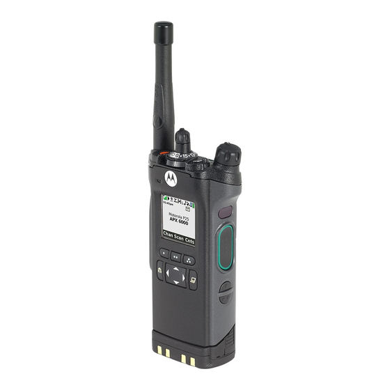
Page 3: Apx Vehicular Adapter (Va) System Compatibility Matrix
APX Vehicular Adapter (VA) System Compatibility Matrix Table 1: APX Vehicular Adapter (VA) Compatible Radios Model Number Description APX6000 APX6000XE P25 Portable Radio. APX6000Li Available in 700/800 MHz, VHF, UHF R1, and UHF R2 bands. APX5000 SRX2200 Table 2: APX Vehicular Adapter (VA) Compatible Batteries... - Page 4 Table 4: APX Vehicular Adapter (VA) Compatible Antennas Compatible Option/Kit Kit Number Description HAD4007 ¼-wave (144 – 150.8) HAD4008 ¼-wave (150.8 – 162) HAD4009 ¼-wave (162 – 174) HAD4021 Wideband (136 – 174) HAD4022 3 dB gain (136 – 174) ...
-
Page 5: Astro™ Apx™ Vehicular Adapter (Apx Va) Rf Energy Exposure And Product Safety
ASTRO™ APX™ Vehicular Adapter (APX VA) RF Energy Exposure and Product Safety Before using this radio, read the information in this section which contains important operating instructions for safe usage and radio RF energy awareness and control information for compliance with RF energy exposure limits in applicable national and international standards. -
Page 6: Federal Communication Commission (Fcc) Regulations
Compliance with RF Exposure Standard Your Motorola two-way radio is designed and tested to comply with a number of national and international standards and guidelines (listed below) regarding human exposure to RF electromagnetic energy. This radio complies with the... -
Page 7: Operating Instructions
• United States Federal Communications Commission (FCC), Code of Federal Regulations; 47 CFR et seq. • FCC, OET Bulletin 65. • Institute of Electrical and Electronic Engineers (IEEE) C95.1. • International Commission on Non-Ionizing Radiation Protection (ICNIRP). • Ministry of Health (Canada) Safety Code 6. •... -
Page 8: Mobile Antenna Installation Guidelines
RF Safety Standard. Approved Accessories • This radio has been tested and meets RF Safety Standards when used with the Motorola accessories supplied or designated for this product. Use of other accessories may result in non-compliance with RF Safety Standards. -
Page 9: Additional Information
• For a list of Motorola-approved antennas and other accessories, visit the following web site which lists the approved accessories for the APX VA or refer to “APX Vehicular Adapter (VA) System Compatibility Matrix” on page 1. http://www.motorolasolutions.com Additional Information... -
Page 10: Compliance And Control Guidelines And Operating Instructions For Mobile Two-Way Radios Installed On Maritime Vessels
Compliance and Control Guidelines and Operating Instructions for Mobile Two-Way Radios Installed on Maritime Vessels If mobile radio equipment is installed on a vessel and operated as a fixed unit, the antenna installation must comply with the following requirements in order to ensure optimal performance and compliance with RF energy exposure limits in the standards and guidelines listed on page 3. -
Page 11: Driver Safety
Vehicles To avoid possible interaction between the radio transmitter and any vehicle electronic control modules, such as ABS, engine, or transmission controls, the radio should be installed only by an experienced installer and the following precautions should be used when installing the radio. 1. -
Page 12: Operational Warnings
If you experience hearing discomfort, ringing in your ears, or muffled speech, you should stop listening to your radio through your headset or earpiece, and have your hearing checked by your doctor. Operational Warnings For Vehicles with an Air Bag Do not mount or place a mobile radio in the area over an air bag W A R N I N G or in the air bag deployment area. -
Page 13: Installation Requirements For Compliance With Rf Energy Exposure Safety Standards
Installation Instructions Introduction This publication describes the complete installation procedure for the ASTRO APX6000 Vehicular Adapter (APX VA) used with APX6000 series radios. Installation includes planning, mounting, and verification. The APX VA allows an APX6000 portable radio (which includes APX6000, APX6000XE, APX6000Li, APX5000, and SRX2200 models) to operate similar to a mobile radio while the radio is in the adapter. -
Page 14: Installation Planning
“APX Vehicular Adapter (VA) System Compatibility Matrix” on page 1. http://www.motorolasolutions.com Installation Planning The Motorola ASTRO™ APX™ Vehicular Adapter (APX VA) is an accessory designed to adapt APX6000 series portable radios for vehicular operation and battery charging. The APX VA System consists of the following components: • console •... -
Page 15: Console Location
• Do insert S-hooks (not provided) on cables into restraining holes for strain relief. • Do use heat-shrink tubing (not provided) on all splices. • Do ensure that unit cables are not placed under stress, are not exposed to weather, and are not subjected to damage due to engine heat. •... -
Page 16: Microphone Bracket Location
• the hang-up location for the microphone. • the microphone’s coil cord length (extended) during operation. • the operability of the radio’s controls while it is in the console. • a substantial structure for accepting mounting screws. • the speaker mounting location and cable length. When possible, mount the console on the floor near the center of the vehicle within easy reach of the operator. -
Page 17: Battery Connections
Battery Connections Determine the best cable route from the rear of the console to the vehicle battery through the engine compartment firewall. The best route should include the shortest path to the battery terminals, yet provide the cable with protection from engine heat. -
Page 18: Microphone Bracket Installation
3. When the bracket is mounted in carpet, the self-tapping screws tend to bind up. To overcome this, tap the screw through the carpet, back out the screw, then tighten the screw down. 1. Use the console to trunnion screws from the kit packaging (unit box). 2. - Page 19 0.125” (0.3175 cm) Dia. Holes Cut-Away of Dash Trunnion Bracket (Optional) Plastic Guides Groove Dash Mount Console Floor Mount Trunnion Bracket (Optional) Legend: No. 10-12 x 1-1/4” Self-Drilling, Self-Tapping Screw (Quantity 4) M5 x 18mm Screws (Quantity 2) Figure 2: Console Installation Detail Bracket 1/8”...
-
Page 20: Visor Microphone Installation
Visor Microphone Installation Note: When connecting the Visor Microphone (RMN5054) to the APX VA, do not connect any wire of the Visor Microphone to pin 17 of Connector J1 on the APX VA. The instructions to do this in the IMPRES Visor Microphone User Guide do not apply to the APX VA product. - Page 21 Before installing an antenna on the trunk lid, • Ensure that the distance from the antenna location on the trunk lid will be at least 36 inches (90 cm) from the front surface of the rear seat-back to ensure compliance with RF Energy Safety Standards. •...
- Page 22 The mini-UHF connector tool (part number HLN6695) is designed to securely tighten the antenna plug-APX VA jack connection without damaging either the plug or the jack. Motorola recommends the following sequence to ensure proper attachment of the system (see Figure 6). Coax Conductor...
-
Page 23: Console Cabling
5. Ensure that the plug’s and jack’s interlocking features are fully seated. Check this by grasping the crimp on the cable jack, rotating the cable, and noting any movement. If the features are seated correctly, there should be NO movement. 6. - Page 24 VEHICLE CHASSIS 13.8 VOLT VEHICLE BATTERY 5-AMP BLADE-TYPE FUSE GROMMET FIREWALL FUSE YELLOW 5-AMP BLADE-TYPE FUSE SWITCHED VEHICLE BLACK ANTENNA OPTIONAL SPEAKER MOBILE MICROPHONE Figure 8: Console Cabling 1. After setting the 2-foot (61 cm) section of the main power cable’s red lead aside for later use, route the main power cable through the firewall and into the vehicle battery area.
- Page 25 Wire Color Connect to Vehicle battery (+) Black Vehicle Chassis (GND) Yellow Fuse box (see below for details) The yellow wire controls whether or not the APX VA radio battery charger will be “live” at all times. Consider the functionality and vehicle battery drain current below during installation. Standard Wiring to Vehicle Switched A+ –...
-
Page 26: Optional External Speaker Installation
6. Dress the cable so that it does not obstruct any vehicle controls nor touch any hot or moving parts of the engine. 7. Connect power cable plug P2 to console jack J2. 8. If the optional external speaker is being installed, connect speaker cable plug P1 to console jack J1. -
Page 27: Led Surveillance Configuration (Option Wiring - User Configurable)
The optional external speaker includes a trunnion bracket that permits the speaker to be mounted in a variety of configurations (see Figure 9). Note: The trunnion bracket is used to permanently mount the speaker on the dashboard or other accessible areas, while permitting the speaker to be tilted to a desired angle. -
Page 28: Installation Verification
Also, check all mechanical parts and wiring for tight and secure mounting. Check for proper operation of the console, microphone, speaker, and radio as described in the User Guide, Motorola Solutions publication MN000350A01-AA. Before placing the radio in the APX VA, check to see that the universal connector cover has been removed from the radio’s... -
Page 29: Vehicles With An Air Bag
Operational Warnings Vehicles With an Air Bag Do not place a portable radio or install radio communications W A R N I N G equipment in the area over an air bag or in the air bag deployment area. Air bags inflate with great force. If a portable radio is placed in the air bag deployment area and the air bag inflates, the radio may be propelled with great force and cause serious injury to occupants of the vehicle. -
Page 30: Operational Cautions
Antenna Information Antennas should be installed according to the installation instructions supplied with the equipment. To ensure compliance with the standards listed above, use only Motorola-approved, supplied antenna or a Motorola-approved replacement antenna. Electronic Devices Most modern electronic equipment, for example, equipment in ambulances, navigation equipment, and so on, is shielded from RF energy, however, RF energy from your APX VA may affect some electronic equipment. -
Page 31: Efficient System Operation
• Do not operate your APX VA unless all RF connectors are properly terminated. • All equipment must be properly grounded according to Motorola’s installation instructions for safe operation. • All equipment should be serviced only by an authorized technician. - Page 32 Condition Description Remedy The LED does not light. The The APX VA has 1. Turn the radio off. radio will not detect the APX experienced a failure. 2. Remove the radio from the VA. If the APX VA is attached APX VA.
-
Page 33: Product Safety And Rf Exposure Compliance
Exposure section of this manual to ensure compliance with RF energy exposure limits. For a list of Motorola-approved antennas, batteries, and other accessories, visit the following web site which lists approved accessories or refer to “APX Vehicular Adapter (VA) System Compatibility Matrix” on page 1. - Page 34 Description The APX™ Vehicular Adapter (APX VA) is an accessory that adapts APX6000 series radios to operate in a vehicular (mobile) environment, and allows in-vehicle battery charging. Note: The APX VA will require the APX Radio (APX6000, APX6000Li, APX6000XE, APX5000, and SRX2200) to have at least Radio Firmware version R13.00.00 and above for full compatibility.
-
Page 35: Loading The Radio Into The Apx Va
In some installations, the ignition switch is bypassed so that the APX VA charges the radio battery with the ignition switch turned off. If this describes your installation, be careful not to discharge the vehicle battery by allowing the APX VA to operate for extended periods of time with a radio loaded and the vehicle ignition switch turned off. - Page 36 Note: Ensure radio is fully seated to bottom of pocket for proper orientation. Figure 12: Radio Installation into APX VA Unit Do not insert the battery alone for charging. 3. Push inward on the Engage Button (see Figure 13) until the radio is securely latched into the APX VA pocket.
-
Page 37: Keylock Security
Flashing RED A charging fault condition exists; check radio battery and its charging contacts. If the fault condition continues, contact your local Motorola representative for assistance. Flashing AMBER Radio battery temperature out-of-range. Allow time for the battery to cool down or warm up. -
Page 38: Operating The Radio
4. If the Surveillance Mode switch option is configured, a switch change only takes effect when the radio is inserted. Operating the Radio All operating conditions of the radio, as described in the applicable radio’s User Guide, apply to operating the radio with the APX VA, except that the hand-held mobile microphone (PTT) is used rather than the radio’s push-to-talk (PTT) switch. -
Page 39: Removing The Radio From The Apx Va
To maintain optimal performance of the contact interface, Motorola Solutions recommends inspecting and cleaning the contacts every 6 months with DeoxIT® GOLD cleaner/lubricant pen (Supplier CAIG Labs, P/N G100P). - Page 40 Troubleshooting LED Connection Error Behavior and other conditions from APX VA User View point: Note: Ensure vehicle ignition is on, Surveillance Mode disabled, and Engage Button fully depressed to facilitate troubleshooting. Condition Description Remedy The LED lights solid Neither a hand mic, nor Note: Microphone accessory should be purple when the a Visor Mic is...
- Page 41 Condition Description Remedy The LED lights solid A hand mic or Visor Note: Microphone accessory should be purple, and displays Mic, is added or installed by the installer. charging status removed after the radio If the user removed any cables, then the error when the radio is is turned on.
- Page 42 Notes...
- Page 44 MOTOROLA, MOTO, MOTOROLA SOLUTIONS and the Stylized M logo are trademarks or registered trademarks of Motorola Trademark Holdings, LLC and are used under license. All other trademarks are the property of their respective owners. © 2015 Motorola Solutions, Inc. All rights reserved.
Need help?
Do you have a question about the APX6000 and is the answer not in the manual?
Questions and answers