Advertisement
Automax Valve Automation Systems
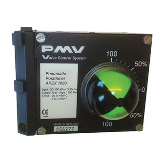
APEX 7000 Pneumatic Positioner
FCD AXENIOM0125-00
Principles of Operation:
The Apex 7000 positioner causes rotation (or linear movement) of valve actuator in proportion to an input signal. This
signal may take the form of pneumatic pressure (Model 7000 and 7600) or electric current (Models 7100,7200 7400
7500). Supply pressure is directed to the actuator through a precision spool valve. As input pressure is varied, the
balance beam shifts away from its neutral position. The spool also shifts and a differential pressure is created across
the actuator causing rotation (or linear movement). Actuator motion is fed back through the positioner shaft and cam.
Cam rotation causes movement of the feedback arm, changing compression in the feedback spring, forcing the
balance beam and spool back to their neutral position. This shuts off the flow of air to the actuator and rotation stops
Installation:
The Apex 7000 positioner can be installed on rotary and linear actuators. Actuators can be either double acting or
spring return. Positioners can be set up for rotation in either direction ( direct or reverse acting).
Supply Air Requirements:
Air pressure must be limited to 150 psi for supply and 30 psi for instrument signal to avoid damage to the positioner.
Supply air must be clean, dry and oil free instrument quality air in accordance with ISA S7.3 specifications ( dew point
>18 degrees below ambient temperature, particle size <5 microns, oil content <1ppm.
Mounting:
The following instructions apply to rotary actuators only. Linear applications require special mounting and coupling
(consult factory).
1. Mount bracket to actuator. Tighten bolts finger tight only at this time. A standard bracket is available for
mounting to NAMUR compliant actuators.
2. Install coupler (not required if installing to a NAMUR compliant actuator) on actuator shaft making sure it is
centered.
3. Verify that orientation of actuator ( and coupler ) flats match positioner shaft flats. If necessary, rotate the cam
before installing positioner ( see "Cam Installation"). NOTE: Actuator should be in orientation corresponding to
zero input signal.
4. Install positioner onto bracket. Make sure positioner shaft and coupler are engaged and centered. Tighten bolts
finger tight only at this time.
Pneumatic Connections: All pneumatic connections, the supply, both output ports, and instrument ports are
female ¼" NPT. All connections require user-supplied tubing fittings. Caution: Do not use Teflon tape as a pipe
thread sealant. Use only a liquid or paste non-hardening pipe sealant on the threads.
5. Connect positioner ports C1 and C2 to actuator. Port C2 is always connected to the actuator port used to drive
actuator away from its start or fail position ( the factor cam setting is full clockwise at minimum input ). Port C1 is
connected to the opposite port or may be plugged for spring return actuators. Note: For fail counterclockwise
applications, the cam must be flipped over so the "R" side is facing upwards (see "Cam Installation").
Installation
Operation
Maintenance
.
Advertisement
Table of Contents

Related Manuals for Flowserve APEX 7000


Summary of Contents for Flowserve APEX 7000
- Page 1 Principles of Operation: The Apex 7000 positioner causes rotation (or linear movement) of valve actuator in proportion to an input signal. This signal may take the form of pneumatic pressure (Model 7000 and 7600) or electric current (Models 7100,7200 7400 7500).
-
Page 2: Cam Adjustment
6. Connect supply air to port marked “S”. Connect instrument signal air to the port marked “I” for model 7000 and 7600. For models 7100, 7200, or 7500, connect 4-20 mA and ground (-). For intrinsically-safe applications (Model 7400 only), see separate intrinsically-safe I/P IOM for barrier requirements and schematics. -
Page 3: Calibration Procedure
Calibration Procedure: 1. Apply 0% input signal (0% = 20 kPa, 3 psi, or 4 mA). 2. Wait for steady state. It is important to wait for steady state. On very large actuators, it can take minutes to establish. 3. Loosen locking screw A about 1 turn, if it is looser, you risk introducing unwanted movement. 4. - Page 4 Cam Adjustment/Replacement: Remove cover and indicator. Loosen the cam lock screw (1) and turn the cam locking nut (2) counter-clockwise until the cam is loose. It may be necessary to brace the output shaft while loosening the cam locking nut. Adjust the cam (3) as desired, making sure that the cam follower (4) always rides on an active lobe on the cam.
- Page 5 Spool Valve Installation: To change out or inspect spool valve, air supply to the positioner must be removed. To remove spool valve: 1. Remove screw (1). 2. Carefully lift out entire spool valve assembly (2), disengaging spool (3) from balance arm (5). To maintain highest performance, do not mix spool and block.
-
Page 6: Electrical Specifications
Consult unit label to determine specific unit certifications. Notes: See hazardous location certificate for detailed temperature ratings. All Apex 7000 units comply with ATEX directive for non-electric equipment intended for use in hazardous locations to Ex II 2 G. -
Page 7: Maintenance
4. Replace filter if necessary and reinstall. Maintenance: The Apex 7000 positioner is designed for long life and trouble-free operation. The following steps should be followed every six months to assure proper operation. 1. Check air supply and associated filtration equipment. See “Supply Air Requirements.”... - Page 8 Spare Parts APEX 7000, 7600 Part No Description Remarks Housing 1 N/A Front Cover Diaphragm cover incl. O-ring Diaphragm Diaphragm washer Balance Arm Feedback spring 3-15 psi assembly Feedback spring 6-30 psi assembly Green Lower arm assembly Spring Twist Stop Pilot valve incl.
- Page 9 Remarks Housing Front Cove incl. O-ring Connecting block NPT ¼” assembly Connecting block G ¼” assembly Relief valve spring Gasket for Apex 7000 Gasket for Apex 7100 Diaphragm cover incl. O-ring Diaphragm Diaphragm washer Balance Arm Feedback Spring 3-15 psi assembly...
- Page 10 Identification cover Plug NPT 1/8” Plug 1/8” G 38-45,75-80 Screw set Apex 7000/7100 6,46-53,67,70,75-80 O-ring set Apex 7000/7100, Nitrile NBR 6,46-53,67,70,75-80 O-ring set Apex 7000/7100, Silicone, Q Spindle adapter I/P box I/P cover incl. screws I/P nose NPT ¼” assembly I/P nose G ¼”...
- Page 11 Flowserve Corporation has established industry leadership in the design and manufacture of its products. When properly selected, this Flowserve product is designed to perform its intended function safely during its useful life. However, the purchaser or user of Flowserve products should be aware that Flowserve products might be used in numerous applications under a wide variety of industrial service conditions.
Need help?
Do you have a question about the APEX 7000 and is the answer not in the manual?
Questions and answers