Advertisement
Quick Links
CONTROLS
WORCESTER
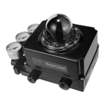
APEX W8000 High-Performance Positioner
FCD WCENIM2078-03
Principles of Operation:
This bulletin is designed to assist in installing, calibrating, troubleshooting and performing maintenance as required for
the APEX W8000 Series high-performance positioner.
Product users and maintenance personnel should thoroughly read and strictly follow the instructions contained in this
bulletin prior to operating the positioner. Any questions concerning this product should be directed to a Flowserve
representative
To avoid possible injury to personnel or damage to valve parts, WARNING and CAUTION notes must be
strictly followed. Modifying this product, substituting non-factory parts or using maintenance procedures
other than outlined could drastically affect performance and be hazardous to personnel and equipment.
The APEX W8000 high-performance positioner is a two-stage device and is designed for use in control loops where
fast response is required. The APEX W8000 positioner is designed to be modular and use the P/P module for 3-15
psi input signal or the NT 3000 Series Transducer Module for 4-20 mA input signal.
The APEX W8000 high-performance positioner is designed as a four-way device, but can easily be converted to a
three-way device by plugging one of the output ports.
NOTE: The APEX W8000 high-performance positioner must use the I/P NT 3000 Transducer. The I/P 2000
Transducer is not acceptable for use with the APEX W8000 Series Positioner.
The APEX W8000 positioner can handle supply pressures up to 150 psi; thus, a supply regulator is usually not
required. However, a five micron air filter is required for pneumatic positioners and a coalescing filter is required for
I/P positioners.
NOTE: The air supply should conform to ISA Standard S7.3 (a dew point at least 18° F / -8° C below ambient
temperature, particle size below 5 microns, oil content not to exceed one part per million).
The APEX W8000 Series positioner features an adjustable gain of 400-1100:1. The medium gain setting is standard
for smaller actuators, while the high gain setting is used on larger actuators (refer to „Gain Adjustment Procedure‟
section for further details.)
OPERATION:
The positioner schematic (Figure 1) shows an APEX W8000 Series positioner connected for double-acting service on
a rotary rack-and-pinion actuator. Tension on the feedback spring provides feedback to the positioner, which varies
as the stem position changes. The spring-loading force is applied through the feed-back linkage and cam to the
positioner‟s input capsule.
Instrument signal pressure is applied between the diaphragms in the input capsule. Therefore, the input capsule
serves as a force-balance member, matching the valve stem position (as measured by tension on the feedback
spring) to the instrument signal.
Installation
Operation
Maintenance
1
Advertisement

Related Manuals for Flowserve APEX W8000


Summary of Contents for Flowserve APEX W8000
- Page 1 The APEX W8000 high-performance positioner is a two-stage device and is designed for use in control loops where fast response is required. The APEX W8000 positioner is designed to be modular and use the P/P module for 3-15 psi input signal or the NT 3000 Series Transducer Module for 4-20 mA input signal.
- Page 2 Figure 1: Apex W8000 Positioner Schematic for Air-to-Open The sequence of operation is as follows: An increase in instrument signal pressure forces the input capsule downward.
- Page 3 Installation of APEX W8000 Series Positioner on Actuators: The APEX W8000 can be installed on most sizes of rotary and linear actuators. Actuators can be either double acting or spring return. Cams can be used for direct acting or reverse acting directions. These instructions apply to rotary actuators only.
- Page 4 APEX W8000 positioners are calibrated at the factory; however, due to shipping and handling, it may be necessary to check the calibration before operating the valve. The APEX W8000 positioner can be calibrated to a range of 3-15; two- way split range, 3-9, or 9-15; and three-way split ranging, 3-7, 7-11, 11-15 psi using the standard feedback spring.
- Page 5 1. For 3-15 or 3-9 psi range, loosen by hand the zero adjustment locking knob and adjust the zero adjustment knob until the valve begins to stroke with more than 3 psi signal (for 9-15 psi range adjust to 9 psi). 2.
- Page 6 Figure 6: Gain Adjustment Gain Adjustment Procedure The unique gain adjustment on the APEX W8000 positioner provides a means to increase or decrease the responsiveness of the valve / actuator / positioner system. Increasing gain makes the valve more responsive and...
- Page 7 1. Before adjusting the gain, place controller on manual and isolate the valve from the process. 2. Turn off supply air to control valve actuator. Using a 5/64-inch allen wrench, loosen both upper and lower lock screws about one half turn. Do not loosen the spacer nut.
- Page 8 Adjusting the Minimum Pressure Cutoff Feature: The APEX W8000 positioner with I/P Transducer has a “Minimum Pressure Cutoff” (MPC) feature, which allows the user to set the positioner. When the input signal falls below a user-adjustable current, the pressure output falls rapidly to approximately 1.7 psi, causing the valve to move to the failure position.
- Page 9 3. Connect an adjustable current source to the terminal block on the circuit board. Apply the desired input signal to the positioner at which the output pressure is to fall to approximately 1.7 psi This signal can range from factory setting of 3.7 to 8 mA.
- Page 10 Remove diaphragm retaining plate (15) from relay diaphragm assembly (13) and relay plate (14) Replace relay diaphragm assembly (13) with one from the positioner repair kit. Place the relay plate (14) between the new diaphragms making sure the 1/16-inch diameter holes between the relay plate (14) and the diaphragm line up. Position diaphragm retaining plate (15) on relay diaphragm assembly with rounded inner diameter edge against diaphragm.
- Page 11 Troubleshooting APEX W8000 Positioners Failure Probable Cause Corrective Action 1. Re-tube to correct ports (see “installation section). 1. Tubing to wrong ports 2. Refer to “installation” section and reverse cam 2. Cam action reversed 3. Feedback lever arm is stuck 3.
- Page 12 50 Zero locking knob 200 Relay Assembly All of the above parts are in stock and can be purchased in a spare parts kit. For selecting and ordering the appropriate kit or a new positioner contact your Flowserve representative or contact the factory.
-
Page 13: Product Nomenclature
Product Nomenclature □ PREFIX I W – Worcester Controls Black Polyester Paint □ MODEL 80 – PP Input 3-15 psi 81 – EP Input 4-20 mA General Purpose 82 – EP input 4-20 mA FM/CSA Explosionproof/Intrinsically Safe (See Note 1) 83 –... - Page 14 Notes: 1. Explosionproof Cl I Div 1 Gr. BCD Cl II Div 1 Gr. EFG, I.S. Cl I II Div 1 Gr ABCDEFG, Non-incendive Cl I Div 2 Gr ABCD 2. ATEX Flameproof II 2 GD Ex d IIB+H2 T6(-40°C to +40°C) tD A21 T40°C 3.
- Page 15 Flowserve Corporation has established industry leadership in the design and manufacture of its products. When properly selected, this Flowserve product is designed to perform its intended function safely during its useful life. However, the purchaser or user of Flowserve products should be aware that Flowserve products might be used in numerous applications under a wide variety of industrial service conditions.
Need help?
Do you have a question about the APEX W8000 and is the answer not in the manual?
Questions and answers