Nonin 8500 Operator's Manual
Handheld pulse oximeter
Hide thumbs
Also See for 8500:
- Operator's manual (33 pages) ,
- Operator's manual (29 pages) ,
- Troubleshooting (2 pages)
Table of Contents
Advertisement
Quick Links
Download this manual
See also:
Operator's Manual
Advertisement
Table of Contents

Related Manuals for Nonin 8500


Summary of Contents for Nonin 8500
- Page 1 Operator’s Manual Model 8500 Handheld Pulse Oximeter English...
- Page 2 E-mail: infointl@nonin.com nonin.com MPS, Medical Product Service GmbH Borngasse 20 D-35619 Braunfels, Germany References to “Nonin” in this manual shall imply Nonin Medical, Inc. Nonin, PureLight and ® nVISION are registered trademarks or trademarks of Nonin Medical, Inc. Microsoft ® Windows are registered trademarks of Microsoft Corporation.
-
Page 3: Table Of Contents
Pulse Quality Indicator.................... 6 Low Battery Indicator....................6 Sensor Fault or Inadequate Signal Display ............6 Using the 8500 Pulse Oximeter ..............8 Unpacking the Model 8500..................8 Installing and Using the Batteries ................8 Important Notes about Battery Use ................ 9 Connecting the Sensor .................. - Page 4 Contents (Continued) Specifications ......................26...
- Page 5 Figures Figure 1. Front View ....................7 Figure 2. Installing Batteries in the 8500 ..............9 Figure 3. Connecting a Sensor................. 10...
- Page 6 Tables Table 1. Labeling Symbols..................4 Table 2. Electromagnetic Immunity................22 Table 3. Electromagnetic Immunity................23 Table 4. Not Applicable.................... 23...
-
Page 7: Indications For Use
To avoid patient injury, use only with Nonin-branded PureLight pulse oximeter sensors. These sensors are manufactured to meet the accuracy specifications for Nonin Pulse Oximeters. Using other manufacturers’ sensors can result in improper pulse oximeter performance. To prevent improper performance and/or patient injury, verify compatibility of the monitor, sensor(s), and accessories before use. -
Page 8: Cautions
This device contains WEEE materials; please contact your distributor regarding take-back or recycling of the device. If you are unsure how to reach your distributor, please call Nonin for your distributor’s contact information. - Page 9 EN 60950, IEC 62368-1, or UL1950 for data-processing equipment. This device is a precision electronic instrument and must be repaired by trained Nonin personnel only. Field repair of the device is not possible. Do not attempt to open the case or repair the electronics. Opening the case may damage the device and void the warranty.
-
Page 10: Guide To Symbols
Guide to Symbols Guide to Symbols This table describes the symbols that are found on the Model 8500 and in this manual. Table 1: Labeling Symbols Symbol Description CAUTION! Follow Instructions for Use. Type BF Applied Part (Patient isolation from electrical shock). - Page 11 Guide to Symbols Table 1: Labeling Symbols (Continued) Symbol Description Pulse Rate Display Pulse Quality Indicator No Alarms Front Panel Buttons Ø Advance/Dimmer Button...
-
Page 12: Displays And Indicators
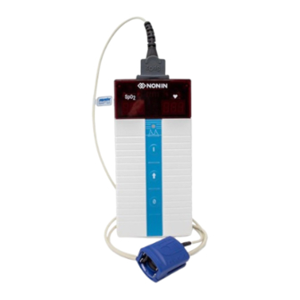
Displays and Indicators Displays and Indicators Display The SpO display is identified by the SpO symbol. This 3-digit light-emitting diode (LED) display shows the current oxygen saturation percentage. Pulse Rate Display The Pulse Rate display is identified by the symbol. - Page 13 Displays and Indicators % Oxygen Pulse Rate Saturation Pulse Quality Indicator On Button Advance/ Dimmer Button Off Button Figure 1: Front View...
-
Page 14: Using The 8500 Pulse Oximeter
Contact the carrier immediately if the shipping carton is damaged. Installing and Using the Batteries The Model 8500 is powered by 6 AA-size alkaline batteries. WARNING: Before changing the batteries, make sure the device is off and the sensor is not applied to a digit. -
Page 15: Important Notes About Battery Use
Using the 8500 Pulse Oximeter Figure 2: Installing Batteries in the 8500 When batteries are critically low, the digital displays will go blank, and the Pulse Quality display will blink amber or red, but not green. After 10 minutes at critically low battery capacity, the pulse oximeter will shut off automatically. -
Page 16: Connecting The Sensor
Using the 8500 Pulse Oximeter Connecting the Sensor Connect the pulse oximeter sensor (with the Nonin logo facing up) to the top of the device as shown. Ensure that the sensor is firmly plugged in. Refer to “Specifications” or to the specific sensor Instructions for Use. -
Page 17: Startup Self-Test
• the software revision number (display in the following order): Main revision “r” + 3 numbers: “n” “n” and “no”. • ( - ) a dash appears for Model 8500 in the displays until a valid pulse signal is detected. Apply the pulse oximeter sensor to the patient’s finger; ensure the system is obtaining an adequate pulse signal by verifying: •... -
Page 18: Detailed Operation
Detailed Operation Detailed Operation Setup Mode Setup mode is used to set the calendar and clock. In Setup mode, the Advance/Dimmer button and the ON ( ) button are used to make all selections. NOTE: Setting the month to “00” disables the calendar function and conserves battery life. Entering Setup Mode 1. -
Page 19: Care And Maintenance
Care and Maintenance Care and Maintenance Clean the device separately from the sensors. For instructions on cleaning pulse oximeter sensors, refer to the respective sensor instructions for use. CAUTION: Do not autoclave or immerse the device or sensors in liquid. Do not expose the device or components to excessive moisture or liquids. -
Page 20: Visual Indicators
Visual Indicators Visual Indicators The intended operator’s position for correctly perceiving a visual signal and its priority is 1 meter (3.3 feet). The following table describes conditions and visual indicators. Condition Visual Indication Pulse Waveform Signal is • Pulse Quality LED blinks red inadequate Sensor Fault (i.e., sensor •... -
Page 21: Communications
Communications Communications Serial Output Models 8500 provides real-time data output capability via the pulse oximeter sensor connector (a 9-pin Sub-D connector). The pulse oximeter sensor connector pin assignments are listed below. Pin Number Assignment ® 1-Wire Infrared Anode, Red Cathode... -
Page 22: Connecting The Device Into A Medical System
Communications Connecting the Device into a Medical System Incorporating the device into a medical system requires the integrator to identify, analyze, and evaluate the risks to patient, operators, and third parties. Subsequent changes to the medical system after device integration could introduce new risks and will require additional analysis. Changes to the medical system that must be evaluated include: •... -
Page 23: Service, Support And Warranty
5 years. Nonin does not recommend field repair of Model 8500. The circuit board in the Model 8500 is a multi-layer board using very narrow traces. Due to the very small trace size, extreme care must be used when replacing components to prevent permanent, non-repairable damage to the circuit board. -
Page 24: Warranty
This warranty shall be the sole and exclusive remedy by the purchaser hereunder for any Model 8500 delivered to the purchaser which is found to be defective in any manner whether such remedies be in contract, tort or by law. -
Page 25: Parts And Accessories
For more information about Nonin parts and accessories: • See the Parts and Accessories List on the Operator’s Manual CD. • Contact your distributor or Nonin at (800) 356-8874 (USA and Canada), +1 (763) 553 9968, or +31 (0)13 - 79 99 040 (Europe). -
Page 26: Troubleshooting
A non-compatible sensor is being used. Replace the sensor with a Nonin- branded PureLight sensor. The ECG monitor may not be Assess the patient. - Page 27 Sensor failure. Replace the sensor. Note: If these solutions do not correct the problem with your device, please contact Nonin Technical Service at (800) 356-8874 (USA and Canada), +1 (763) 553-9968, or +31 (0)13 - 79 99 040 (Europe).
-
Page 28: Technical Information
Accuracies may be affected as a result of exposure to electromagnetic disturbances that are outside of the environments listed in the Indications For Use. If issues are experienced, move the Nonin system away from the source of electromagnetic disturbances. -
Page 29: Table 3. Electromagnetic Immunity
Technical Information Table 3: Electromagnetic Immunity Immunity Test Compliance Electrostatic Discharge (ESD) ±8 kV contact IEC 61000-4-2 ±15 kV air Power Frequency (50/60 Hz) Magnetic Field 30 A/m IEC 61000-4-8 80 MHz – 2.7 GHz 10 V/m 380 – 390 MHz 27 V/m 430 –... -
Page 30: Equipment Response Time
Technical Information Equipment Response Time If the signal from the sensor is inadequate, the last measured SpO and pulse rate values freeze for 10 seconds and are then replaced with dashes. Values Average Latency Standard/Fast Averaged SpO 4 beat exponential 2 beats Pulse Rate Values Response... -
Page 31: Testing Summary
Technical Information Testing Summary accuracy, and low perfusion testing was conducted by Nonin Medical, Inc., as described below: Accuracy Testing During motion and no-motion conditions at an independent research laboratory, SpO accuracy testing is conducted during induced hypoxia studies on healthy, male and female, non-smoking, light- to dark-skinned subjects that are 18 years of age and older. - Page 32 18 to 321 beats per minute (BPM) Accuracy - Sensors Declared accuracy data for compatible sensors can be found in Nonin’s Sensor Accuracy document. Measurement Wavelengths and Output Power* Red: 660 nanometers @ 0.8 mW max. avg. Infrared: 910 nanometers @ 1.2 mW max. avg.
Need help?
Do you have a question about the 8500 and is the answer not in the manual?
Questions and answers