
Related Manuals for Taga Harmony TA-400MIC


Summary of Contents for Taga Harmony TA-400MIC
- Page 1 TA-400MIC CUSTOM INSTALL A/B SPEAKER STEREO AMPLIFIER Instruction Manual Edition 12-17...
- Page 2 It delivers pure and distortion-limited power as well as rich sound performance with stunning accuracy, soundstage and sensational dynamics. A variety of features and wired connections makes the TA-400MIC a very versatile device with ability to work in different applications: Built-in headphone output is a perfect choice for those who prefer discrete listening.
-
Page 3: Safety Instructions
Safety Instructions IMPORTANT READ THIS SECTION CAREFULLY BEFORE PROCEEDING! WARNING: TO REDUCE THE RISK OF FIRE OR ELECTRIC SHOCK, DO NOT EXPOSE THIS PRODUCT TO RAIN OR MOISTURE. DO NOT REMOVE CHASSIS (OR BACK). NO USER-SERVICEABLE PARTS INSIDE. REFER SERVICING TO QUALIFIED SERVICE PERSONNEL. The triangle containing a lightning symbol is intended to alert the user to the presence of uninsulated dangerous voltages within the product’s enclosure that me be of sufficient magnitude to constitute a risk of electric shock to persons. -
Page 4: Important Safety Instructions
Important Safety Instructions 1. Read Instructions – All the safety and operating instruc- 13. Overloading - Do not overload wall outlets, extensions tions should be read before the product is operated. cords, or integral convenience receptacles as this cas 2. Retain Instructions – The safety and operating instruc- result in a risk of fire or electric shock. -
Page 5: Front And Rear Panel
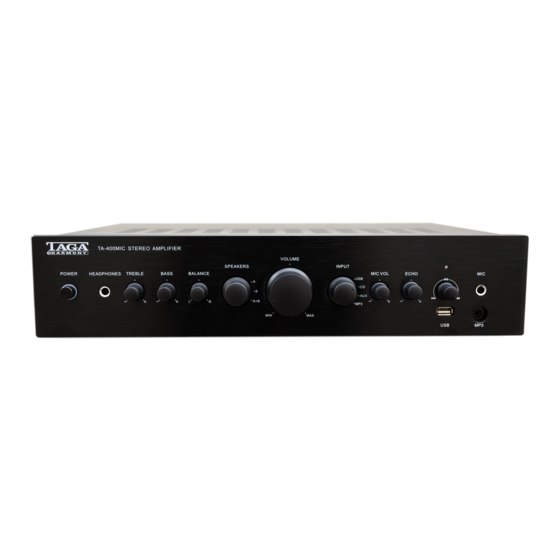
Front and Rear Panel Front panel: Power Switch and Power Status Indicator (around the Power Switch) Headphone ¼” Jack Output Treble Regulator Bass Regulator Balance Regulator Speaker Selector (A, B, A+B) Volume Regulator Input Selector (USB, CD, AUX, MP3) Microphone Level Regulator 10. -
Page 6: Hooking Up Speaker Cables
Hooking Up Speaker Cables The Speaker Connectors can accommodate up to 10AWG speaker cables as well as most of popular plugs (banana etc.). A 10AWG cable is recommended for longer connections (greater than 20 meters / 66 feet). For shorter lengths you can use 12/14 or 18 AWG cables. -
Page 7: Hooking Up The Amplifier
Hooking up the Amplifier CD Player, CD Player, TAPE, Satellite tuner, etc. Satellite tuner, etc. CD Recorder RCA interconnect cable Speaker cable Group A Group B Make sure the amplifier is switched off (the Power Switch is in the top position and the Power Cable is removed). -
Page 8: Operation - Basic
Operation - Basic Plug the Power Cable to the amplifier and into the electrical outlet. Switch on the amplifier – press the Power Switch (the Power Switch should be in the down position). The status LED around the Power Switch should turn blue in a few seconds. - Page 9 Operation - Connecting Additional Devices Microphone Headphones Smartphone, tablet, etc. USB stick Note! Turn the Volume Regulator to MIN (max counter clockwise) before connecting or disconnecting any additional device. Headphones: When headphones (not supplied with this product) are plugged to the headphone input (Headphones) the transmission of sound to the speakers is switched off.
- Page 10 Operation - Connecting Additional Devices Microphone: This amplifier allows a connection of a wired microphone (not supplied with this product) and easy voice mixing with the background music. MIC VOL: You can adjust the sound level of the microphone relative to the currently played background music.
-
Page 11: Troubleshooting
Troubleshooting If the amplifier is not operating properly, make a check of the items in the table below. If the problem still resists, a malfunction may be assumed. Disconnect the power immediately and contact the store where the amplifier was purchased. Problem Causes Corrections... - Page 12 We strongly advise to contact a professional installer or dealer in order to install TAGA Harmony products. We recommend using high quality TAGA Harmony speaker cables and other installation accessories. Kit Content: Amplifier Power Cable Instruction Manual Your product is marked with the symbol as showed on the left.
Need help?
Do you have a question about the TA-400MIC and is the answer not in the manual?
Questions and answers