
Subscribe to Our Youtube Channel
Related Manuals for Taga Harmony TTA-500


Summary of Contents for Taga Harmony TTA-500
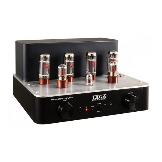
- Page 1 TTA-500 CLASS AB VACUUM TUBE STEREO AMPLIFIER INPUT VOLUME POWER LINE Instruction Manual Edition 02-18...
- Page 2 Analog inputs with high-end solid machined brass RCA sockets can accommodate up to 3 stereo devices. The preamplifier input (HT input) is dedicated for using the TTA-500 as a tube power amplifier and allows to connect it to your Home Theatre system (AV receiver or amp)
-
Page 3: Table Of Contents
Contents Safety Instructions Important Safety Instructions Controls and Displays Remote Controller Front and Rear Panel Top Tube Panel Hooking Up Speaker Cables Hooking Up The Amplifier Operation Additional Information Specifications... -
Page 4: Safety Instructions
Safety Instructions IMPORTANT READ THIS SECTION CAREFULLY BEFORE PROCEEDING! WARNING: TO REDUCE THE RISK OF FIRE OR ELECTRIC SHOCK, DO NOT EXPOSE THIS PRODUCT TO RAIN OR MOISTURE. DO NOT REMOVE CHASSIS (OR BACK). NO USER-SERVICEABLE PARTS INSIDE. REFER SERVICING TO QUALIFIED SERVICE PERSONNEL. The triangle containing a lightning symbol is intended to alert the user to the presence of uninsulated dangerous voltages within the product’s enclosure that may be of sufficient magnitude to constitute a risk of electric shock to persons. -
Page 5: Important Safety Instructions
Important Safety Instructions 1. Read Instructions – All the safety and operating instructions 13. Overloading - Do not overload wall outlets, extensions should be read before the product is operated. cords, or integral convenience receptacles as this can 2. Retain Instructions – The safety and operating instructions result in a risk of fire or electric shock. -
Page 6: Controls And Displays
Controls and Displays Remote Controller Battery Installation Note! Batteries are not supplied with this product. Prepare two AAA batteries. Unscrew the screws on the rear of the remote controller. Remove the rear cover. Insert the batteries into the battery compartment. Carefully follow the polarity diagram inside the battery compartment ( positive + and negative - symbols). -
Page 7: Front And Rear Panel
HT (PRE IN) Input Selector Button CD Input Selector Button AUX Input Selector Button Line Input Selector Button Volume Buttons (▼ / ▲) Front and Rear Panel TTA-500 STEREO AMPLIFIER TT A- 500 S TERE O AMPLIFIE R INPUT VOLUME POWER LINE... -
Page 8: Top Tube Panel
Front and Rear Panel Rear Panel: Analog Stereo RCA Inputs AUX / LINE / CD 10. (HT) Preamplifier Stereo RCA Input 11. Speaker Right Channel Output (Speaker Connectors) 12. Speaker Left Channel Output (Speaker Connectors) 13. Power Cable Input and Fuse Box Note! A blown fuse should be only exchanged for exactly the same type as indicated on the rear amplifier panel. -
Page 9: Hooking Up Speaker Cables
Hooking Up Speaker Cables The Speaker Connectors can accommodate up to 10AWG speaker cables as well as most of popular plugs (banana etc.). A 10AWG cable is recommended for longer connections (longer than 20 meters / 66 feet). For shorter lengths you can use 12/14 or 18 AWG cables. - Page 10 Note! Never perform this operation while the amplifier is turned on [turn off the amplifier and remove the Power Cable] – it can damage this amplifier or speakers. This may void your warranty. Note! Make sure to select the same mode (Triode or Pentode) for both channels. 4.
-
Page 11: Operation
Operation Plug the Power Cable to the amplifier and into the electrical outlet. Turn on the amplifier – press the Power Switch (the Power Switch should be in the down position). The status LED located on the Volume Regulator should turn red in approximately 30 seconds. -
Page 12: Additional Information
Additional information Break-In Your TAGA Harmony amplifier sounds great immediately after it is taken out of the carton but as all vacuum tube amplifiers, this amplifier requires a “break-in” period to reach its full sonic capabilities. During the “break-in” period it is recommended to operate the amplifier at moderate volume levels. -
Page 13: Specifications
7. Make sure to reinstall the cage for the regular operation. Vacuum Tube Biasing (EL34) Only the output power tubes (EL34) need to be biased manually. This procedure requires to open the amplifier and we recommend to contact TAGA Harmony authorized service center to perform it. Triode and Pentode Mode Selecting the desired mode of operation for the output power vacuum tubes (EL34) allows to modify the sound of the amplifier. - Page 14 Notes...
- Page 15 Notes...
- Page 16 We strongly advise to contact a professional installer or dealer in order to install TAGA Harmony products. We recommend using high quality TAGA Harmony speaker cables and other installation accessories. Kit Content: Amplifier with Tube Cage installed 1EA Remote Controller...
Need help?
Do you have a question about the TTA-500 and is the answer not in the manual?
Questions and answers