Milwaukee 5339-20 Repair Instructions
Sds max demolition hammer sds max rotary hammer
Hide thumbs
Also See for 5339-20:
- Operator's manual (33 pages) ,
- Operator's manual (18 pages) ,
- Operator's manual (29 pages)

Related Manuals for Milwaukee 5339-20


Summary of Contents for Milwaukee 5339-20
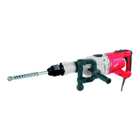
- Page 1 REPAIR INSTRUCTIONS Cat. No. 5339-20 SDS Max Demolition Hammer Cat. No. 5342-20 SDS Max Rotary Hammer MILWAUKEE ELECTRIC TOOL CORPORATION 13135 W. LISBON ROAD • BROOKFIELD, WISCONSIN 53005-2550 58-92-5305 d1 022005...
-
Page 2: Removing The
PAGE REPAIR INSTRUCTIONS 58-92-5305 d1 Special Tools – Forcing discs 61-10-0011 Require – Hex key 4 mm – Hex key 5 mm – Sleeve 61-10-0013 – Pin-type face spanner 61-10-0012 – Spindle Fixture (optional) 61-30-0290 61-10-0011 61-10-0012 61-10-0013 61-30-0290 Important! –... - Page 3 PAGE REPAIR INSTRUCTIONS 58-92-5305 d1 Removing the Remove both retainers (1). spring ring Slightly spread spring ring (2) and pull it off the machine towards the front. Removing the Position machine in a vertical position. end cover cap Depress sleeve (2) and remove end cover cap (1) with aid of a screwdriver.
- Page 4 PAGE REPAIR INSTRUCTIONS 58-92-5305 d1 Removing the Remove four screws (1) with a 5 mm hex seal retainer key. Turn seal retainer (2) 45° and remove it with a plastic face hammer from below (see illustration). Removal of seal retainer (2) only re- quires light hammer blows at each of the four screw holes.
- Page 5 PAGE REPAIR INSTRUCTIONS 58-92-5305 d1 Removing the Remove adjusting plate assembly (4) from lever pin (2) located on lever (1). Squeeze spring (5) together at the bottom side of lever (1) and remove lever from gear box cover. Remove O-ring (3). When removing adjusting plate (4) from pin (2) take care to not bend spring assembly.
-
Page 6: The Spindle As
PAGE REPAIR INSTRUCTIONS 58-92-5305 d1 Disassembling Remove thrust collar (1) from spindle (4). the spindle as- Remove O-ring (2) from thrust collar (1). sembly Remove ram assembly (5) from spindle (4) by tapping it lightly with a plastic face hammer. Remove O-ring (6) from ram (5). -
Page 7: Sembly
PAGE REPAIR INSTRUCTIONS 58-92-5305 d1 Removing the Position piston assembly (5) into the back piston assembly dead center position. Combined drill/chisel hammer: Remove spindle bevel gear (3) from gear box. Remove set collar (1) and locking plate (2) from gear box. Remove the piston assembly (5) upwards. -
Page 8: Washers (4)
PAGE REPAIR INSTRUCTIONS 58-92-5305 d1 Disassembling Remove three hex head screws (8) from the armature bearing end plate (7) and pull complete ar- mature assembly (B) with bearing end plate (7) from gear box (1). Remove o-ring (2) from gear box (1). Insert the pin-type face spanner (61-10- 0012) (3) into seal nut (4) and remove seal nut (4) counter-clockwise. - Page 9 PAGE REPAIR INSTRUCTIONS 58-92-5305 d1 Removing the Remove two screws (1) and remove lower lower gear box gear box cover (2). cover The exposed plane surface serves only for manufacturing the gear box and has no other function! Disassembling Remove the four screws (1) from the the electronic handle and remove handle half (2).
- Page 10 PAGE REPAIR INSTRUCTIONS 58-92-5305 d1 Removing the Remove air deflector ring (5). anti-vibration Remove screw (4). Remove the following mechanism parts of the anti-vibration mechanism from and the field motor housing (8): – thrust piece (1) – spring (2) – vibration lever(3). Caution: Screw (4) and vibration spring cover (1) are under spring pressure.
-
Page 11: Maintenance
PAGE REPAIR INSTRUCTIONS 58-92-5305 d1 Maintenance General It is recommended that maintenance be performed on the machine at regular intervals or when the car- bon brushes reach end of life. Cleaning Clean all parts – with the exception of the electrical parts and clutch– with cold cleaning solvent. Cau- tion! No cleaning solvent should penetrate into the bearing. - Page 12 PAGE REPAIR INSTRUCTIONS 58-92-5305 d1 Lubrication: Combined drill/chisel hammer (5342-20)
- Page 13 PAGE REPAIR INSTRUCTIONS 58-92-5305 d1 Lubrication: Chisel hammer (5339-20)
- Page 14 PAGE REPAIR INSTRUCTIONS 58-92-5305 d1 Sequence and torques of the screws:...
- Page 15 PAGE REPAIR INSTRUCTIONS 58-92-5305 d1 Assembly Installing the Install field (6) into motor housing (8) and anti-vibration secure it with two screws (7) (torque = 2 mechanism Nm / 18 in. lbs.). and field Install following parts of the anti-vibration mechanism into motor housing (8): –...
-
Page 16: Washer (2)
PAGE REPAIR INSTRUCTIONS 58-92-5305 d1 Installing the Secure gear box cover (2) with two screws gear box cover (1) onto the gear box (torque = 3 Nm / 27 in. lbs.). Combined Place caged needle bearings (1) into lu- bricated steel sleeve in gear box (2). drill/chisel hammer: Install clutch assembly (3) into gear box... - Page 17 PAGE REPAIR INSTRUCTIONS 58-92-5305 d1 Assembling the 1 Press bearing (B) onto armature shaft and armature install bearing cup (C) into rear bearing bore of motor housing (not shown). 2 See illustration below: Refer to chart”A” below when removing or installing the armature fan.
- Page 18 PAGE REPAIR INSTRUCTIONS 58-92-5305 d1 ® Installing the 1 Apply Blue loctite onto four screws (4). motor housing Install gear box and armature (5) into mo- tor housing (6) and tighten four screws (4) cross-wise (torque = 13 Nm / 115 in. lbs.). 2 Install and connect carbon brushes (3) on both sides (refer to wiring instruction bulle- tin).
-
Page 19: O-Ring (3)
PAGE REPAIR INSTRUCTIONS 58-92-5305 d1 Assembling Install thrust washer (C), back-pressure o- the spindle ring (B), and thrust collar (A) into spindle (E). Lubricate prior to assembly. Mind the right position when installing thrust collar (A): the bevel-edge of thrust collar (A) must face striker (8)! Check: should striker guide (6) or rollers (D) be damaged or burred, all parts must to be replaced (striker and... - Page 20 PAGE REPAIR INSTRUCTIONS 58-92-5305 d1 SDS Max 1 Secure hammer gear box in a machinists vise. combined drill/chisel 2 Install service fixture #61-10-2060 into hammer: front spindle. 3 Engage / lock external splines of set collar into internal splines of spindle bevel gear To check static (figs.
- Page 21 PAGE REPAIR INSTRUCTIONS 58-92-5305 d1 Combined 1 Install complete spindle assembly (1) into gear box (2) as far as it will go, aligning ex- drill/chisel ternal splines on spindle (1) with internal hammer: splines of previously installed spindle bev- el gear. Installing the Piston assembly must enter the rear/end spindle...
- Page 22 PAGE REPAIR INSTRUCTIONS 58-92-5305 d1 Installing the Install O-Ring (3) into opening of gear box lever cover (4). Squeeze together spring (6) at bottom side of lever and insert it sideways into opening of gear box cover (4), beginning at the two lugs (7). Set the lever (1) to 0.
- Page 23 PAGE REPAIR INSTRUCTIONS 58-92-5305 d1 Installing the 1 Install o-ring (1) onto thrust collar (2). thrust collar 2 Position thrust collar assembly (1,2) into gear box (3) until the outside face of the thrust collar assembly (1,2) is flush with the face of the gear box (3).
- Page 24 PAGE REPAIR INSTRUCTIONS 58-92-5305 d1 Installing the end Install the following parts: cover cap – interlock sleeve (6) – damping ring (5) – damping element / washer (4). Install retaining ring (3), if necessary use two screwdrivers for support. Retaining ring (3) must lock into groove (7) of spindle! Install sleeve (2) in direction of arrow.
-
Page 25: Electrical Test
PAGE REPAIR INSTRUCTIONS 58-92-5305 d1 Installing Press retainers (2) together on both sides the handle and install handle (4). Insert screw (1) and screw down knob (3). Installing the Screw down the auxiliary handle (1). auxiliary handle TEST RUN - Run tool for a 5 minute run-in period.
Need help?
Do you have a question about the 5339-20 and is the answer not in the manual?
Questions and answers