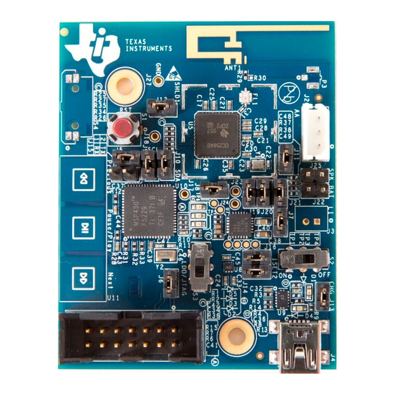
Summary of Contents for Texas Instruments TUSB3200EVM2
- Page 1 6 Channel TUSB3200EVM2 for the TUSB3200A USB Streaming Data Controller User’s Guide January 2003 Digital Audio SLAU062A...
- Page 2 IMPORTANT NOTICE Texas Instruments Incorporated and its subsidiaries (TI) reserve the right to make corrections, modifications, enhancements, improvements, and other changes to its products and services at any time and to discontinue any product or service without notice. Customers should obtain the latest relevant information before placing orders and should verify that such information is current and complete.
- Page 3 Related Documentation From Texas Instruments Preface Read This First About This Manual This user’s guide describes the setup and operation of the TUSB3200EVM2 platform. How to Use This Manual This document contains the following chapters: Chapter 1—Equipment Chapter 2—Detailed Description of the TUSB3200EVM2 Appendix A—Schematic Diagrams...
-
Page 5: Table Of Contents
........Detailed Description of the TUSB3200EVM2 . -
Page 7: Equipment
Chapter 1 Equipment This user’s guide describes the setup and operation of the TUSB3200EVM2 platform. This PCB contains two main active parts: TUSB3200A STC (TI USB streaming controller) and crystal CS4228 codec. This PCB is referred to as the TUSB3200EVM2 from this point on. Familiarity with emulator hardware and software is required and assumed throughout this user’s guide. -
Page 8: Hardware
EEPROM is inserted in the 8-pin DIP socket. The jumper configuration for the internal mode is listed in Table 1–1. Use the following procedure for EEPROM evaluation: Set J8 to position 1–2 to bus-power the TUSB3200EVM2; set J8 to 2–3 to put the TUSB3200EVM2 in self-powered mode (a power supply is required). -
Page 9: In-Circuit Emulator (Ice) Evaluation
Install the emulator. Refer to the respective ICE user’s guide for the emula- tor. Attach emulator POD to TUSB3200EVM2 ICE Socket (J3). A 40-pin ex- tension adapter may be required to allow enough clearance for access to the buttons, jumpers, and connectors. Pin 1 is designated by a triangle on the opposite side of the J3 reference designator. -
Page 11: Detailed Description Of The Tusb3200Evm2
Chapter 2 Detailed Description of the TUSB3200EVM2 This chapter presents a detailed description of the TUSB3200EVM2. Topic Page TUSB3200EVM2 Setup ........ -
Page 12: Tusb3200Evm2 Setup
EVM board and another end of the cable to a PC root port. 2.4 Light Emitting Diode (LED) A set of green and yellow LEDs is installed on the TUSB3200EVM2 board for quick and easy GPIO evaluation. The green LEDs are connected to port 1 bits 0 through 7 of the in-circuit emulator for external mode. -
Page 13: Jumpers
MCU mode GPIO P3.4 general-purpose momentary button external MCU mode GPIO P3.5 general-purpose momentary button external MCU mode Position 1–2: Self-powered mode; Position 2–3: Bus-powered mode Reset Reset EVM platform and in-circuit emulator (external mode) Detailed Description of the TUSB3200EVM2... -
Page 14: Complete Analog Stage
2.7 EEPROM The EEPROM is used to set up the TUSB3200EVM2. The EEPROM is recommended to be 8K bytes to match the RAM memory size. Firmware for the TUSB3200EVM2 must be loaded for correct operation. An 8-pin DIP socket allows easy installation and removal of the EEPROM.


Need help?
Do you have a question about the TUSB3200EVM2 and is the answer not in the manual?
Questions and answers