Advertisement
Quick Links
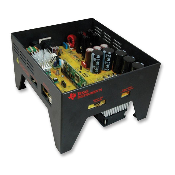
High Voltage Digital Motor Control Kit (R1.1) Quick Start Guide
The High Voltage Digital Motor Control (DMC) and Power Factor Correction (PFC) kit (TMDSHVMTRPFCKIT),
provides a great way to learn and experiment with digital control of high voltage motors.
The High Voltage Digital Motor Control Kit contains:
F28035 and F28335 controlCARDs
High Voltage DMC board with slot for the controlCARD
15V DC Power Supply
AC power Cord, Banana Plug Cord, USB Cable
CCSv5 CD & USB Stick with Quick Start GUI and Guide
This EVM should be used only by qualified engineers and technicians who are familiar with
the risks associated with handling electrical and mechanical components, systems and
subsystems. The EVM operates at voltages and currents that can result in electrical shock,
fire hazard and/or personal injury if not properly handled or applied. Users must use the
equipment with necessary caution and employ appropriate safeguards to avoid serious
injury. Users must not touch any part of the EVM while energized.
C2000™ Systems Applications Collateral
Fig1: TMDSHVMTRPFCKIT
WARNING
1
v2.0
Advertisement

Subscribe to Our Youtube Channel
Related Manuals for Texas Instruments TMDSHVMTRPFCKIT


Summary of Contents for Texas Instruments TMDSHVMTRPFCKIT
- Page 1 High Voltage Digital Motor Control Kit (R1.1) Quick Start Guide Fig1: TMDSHVMTRPFCKIT The High Voltage Digital Motor Control (DMC) and Power Factor Correction (PFC) kit (TMDSHVMTRPFCKIT), provides a great way to learn and experiment with digital control of high voltage motors.
- Page 2 C2000™ Systems Applications Collateral Features of the High Voltage Motor Control and PFC Board: 3-Phase Inverter Stage capable of sensorless and sensored field oriented control (FOC) of high voltage ACI and PMSM motor and trapezoidal & sinusoidal control of high voltage BLDC motor. 350V DC max input voltage and 1kW* maximum load in the configuration shipped.
- Page 3 Fig 2, illustrates a typical motor drive system running from AC power and various blocks that make up such a system. All these power/control blocks are present on the TMDSHVMTRPFCKIT board in form of macro blocks. Below is a list of all the macro blocks names and numbers present on the board and a short description of it’s function, Fig 3, shows the location of these block on the motor control board and a few key connector location.
- Page 4 C2000™ Systems Applications Collateral [Main]-BS5 [Main]-BS5 Inv-BUS Input Inv-BUS Input PFC-2PhiL Macro PFC-2PhiL Macro [Main]-TB3 [Main]-TB3 [M4] [M4] Motor Connector Motor Connector Terminal Block Terminal Block Inverter3Ph-HV- Inverter3Ph-HV- 3Shunt Macro 3Shunt Macro [M5] [M5] [Main]-P1 [Main]-P1 AC Power Input AC Power Input C2000 C2000 Aux Power...
- Page 5 C2000™ Systems Applications Collateral 5) Make sure that the following switches are set as described below on the F28035 control card to enable boot from flash and connection to the SCI a. SW1 is in the OFF position b. SW2 on controlCARD, Position 1 = ON, Position 2 = ON c.
- Page 6 C2000™ Systems Applications Collateral Software Setup The QSG GUIs (HVMTRPFCKIT-PM-ACI-GUI.exe and HVMTRPFCKIT-BLDC-GUI.exe) are located in the drive that is shipped with the kit or once controlSUITE is installed at the following location: controlSUITE\developement_kits\HVMotorCtrl+PfcKitv_2.0\~GUI\ HVMTRPFCKIT-PM-ACI-GUI.exe (default) controlSUITE\developement_kits\HVMotorCtrl+PfcKit_v2.0\~GUI\ HVMTRPFCKIT-BLDC-GUI.exe The kit ships with a F28035 controlCARD which is pre-flashed with the PM & ACI code that enables interface to PM-ACI GUI.
- Page 7 C2000™ Systems Applications Collateral Fig4: GUI Startup for PM and ACI motors 3) If an incorrect image is flashed on the controlCARD, the connection will fail. In this case it is recommended to reflash the controlCARD with the correct image. 4) Now connect the other end of the AC power cord to mains/wall power outlet.
- Page 8 C2000™ Systems Applications Collateral 6) The GUI should auto-detect and connect to your HVDMC Kit. If auto-connect fails you will need to set up the connection manually. The Connection Wizard is accessed through the Connection menu. Click on “Connect to engine” to view a list of available targets. Now setup the Connection Wizard Dialog to match Fig 5.
- Page 9 C2000™ Systems Applications Collateral 7) After the connection is established to the controller the type of motor can be selected by clicking on the check box. Also note if BLDC motor is being used with wall supply of >120V AC a step down transformer must be used as the BLDC motor is rated for 160V, otherwise an over voltage condition flag would be displayed.
- Page 10 C2000™ Systems Applications Collateral References For more information please refer to the following: Download and Install ControlSUITE www.ti.com/controlSUITE F28xxx User’s Guides http://www.ti.com/f28xuserguides After controlSUITE install HighVoltageMotorCtrl+PFC HW Reference Guide – provides detailed information on the High voltage motor control and PFC kit hardware.
Need help?
Do you have a question about the TMDSHVMTRPFCKIT and is the answer not in the manual?
Questions and answers