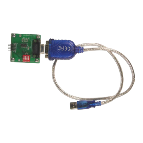
Fujitsu F2MC-16LX Series Application Note
Hide thumbs
Also See for F2MC-16LX Series:
- Hardware manual (724 pages) ,
- Operation manual (10 pages) ,
- Application note (23 pages)
Advertisement
Quick Links
Download this manual
See also:
User Manual
Application Note
© Fujitsu Mikroelektronik GmbH, Microcontroller Application Group
History
th
10
Oct. 00
NFl
th
26
Apr. 01
NFl
rd
23
Aug. 01
NFl
th
27
Aug. 01
NFl
th
18
Jul. 02
NFl
EMC Design Guide
F²MC-16LX Family
V1.0
Initial draft
V1.1
Oscillator circuit added
V1.2
Recommended layout, power supply routing added
V1.3
Layout rules added
V1.4
Description DeCap added
1
Advertisement

Summary of Contents for Fujitsu F2MC-16LX Series
- Page 1 Application Note EMC Design Guide F²MC-16LX Family © Fujitsu Mikroelektronik GmbH, Microcontroller Application Group History Oct. 00 V1.0 Initial draft Apr. 01 V1.1 Oscillator circuit added Aug. 01 V1.2 Recommended layout, power supply routing added Aug. 01 V1.3 Layout rules added Jul.
- Page 2 Warranty and Disclaimer To the maximum extent permitted by applicable law, Fujitsu Mikroelektronik GmbH restricts its warranties and its liability for all products delivered free of charge (eg. software include or header files, application examples, application Notes, target boards, evaluation boards, engineering samples of IC’s etc.), its performance and any...
-
Page 3: Table Of Contents
Table of Contents: Introduction Rules to create a good Layout Crystal Oscillator Circuit Power supply routing Noise reduction for general IO pins Function of certain MCU pins EMI Measurement for LX16-family... -
Page 4: Introduction
The measured emissions are no data, which are specified in the DS of the microcontroller series. During the last designs the EMI of the Fujitsu 16LX microcontroller series could be reduced step by step. The PLL multiplier circuit allows the usage of low crystal frequency to reduce high-frequency noise from the oscillator circuit. -
Page 5: Crystal Oscillator Circuit
3. Crystal Oscillator Circuit Figure 1 shows the oscillator for the Fujitsu 16-bit family. For best performance, the PCB layout of this circuit should cover only a very small area. For the layout is recommended a PCB with two or more layers. Make sure to provide bypass capacitors via shortest distance from X0, X1 pins, crystal oscillator, and ground lines. -
Page 6: Power Supply Routing
4. Power supply routing One topic our noise reduction technology is lowering internal power supply voltage on 3V level to reduce the current flow. Fig. 2 shows the structure of 5V and 3V power supply. I/O-PORT FLASH Vcc3 3V Regulator SCI / TIMER / etc A/D+D/A AVcc... - Page 7 The high-speed current (di/dt) will be supported from the decoupling capacitor only. Therefore use traces with max. width and min. length between Vss/Vcc pin and DeCap. After DeCap use thin traces to route the trace to the power supply system. use EMC filter for short length µC-supply...
- Page 8 For 2-layer boards should be used a closed ground plane (located directly below the MCU). The Vcc supplies should be taken from the bottom layer. For 4-layer boards should be used the inside layers for GND and Vcc supplies. In this case, both layers form additional capacitor (broadband behaviour) for the power supply.
-
Page 9: Noise Reduction For General Io Pins
5. Noise reduction for general IO pins To reduce noise, make sure to connect the Vss or Vcc with smoothed power supply, because the noise on the power supply will also distributed via IO-pin, which is configured as static low or high output. Figure 9 shows an example to reduce the noise on output lines. µC µC IO-Port... -
Page 10: Function Of Certain Mcu Pins
6. Function of certain MCU pins Pin name Pin no. Function Main supply for IO buffer MCU core close to input the internal 3.3V regulator close to crystal oscillator Main supply for IO buffer and MCU core close to the internal 3.3V regulator close to crystal oscillator External smooth capacitor for internal 3.3V regulator output, it is used for supply of the MCU core... -
Page 11: Emi Measurement For Lx16-Family
7. EMI Measurement for LX16-family Schirmbox Spectrum analyzer 0.1-1000MHz 10Ai Power supply 10Ai X-TEM Ferrit Filter Filter IEEE RS232 Workstation Figure 10: Measuring setup CKSCR Remarks 16 MHz 0xBB default after reset 12 MHz 0xBA 8 MHz 0xB9 4 MHz 0xB8 2 MHz 0xDC...


Need help?
Do you have a question about the F2MC-16LX Series and is the answer not in the manual?
Questions and answers