Fujitsu F2MC-16LX MB90420G Series Hardware Manual
16-bit microcontroller
Hide thumbs
Also See for F2MC-16LX MB90420G Series:
- Hardware manual (706 pages) ,
- Application note (13 pages) ,
- Operation manual (10 pages)

Related Manuals for Fujitsu F2MC-16LX MB90420G Series


Summary of Contents for Fujitsu F2MC-16LX MB90420G Series
- Page 1 FUJITSU SEMICONDUCTOR CM44-10113-3E CONTROLLER MANUAL MC-16LX 16-BIT MICROCONTROLLER MB90420G/425G Series HARDWARE MANUAL...
- Page 3 Be sure to refer to the “Check Sheet” for the latest cautions on development. “Check Sheet” is seen at the following support page URL : http://www.fujitsu.com/global/services/microelectronics/product/micom/support/index.html “Check Sheet” lists the minimal requirement items to be checked to prevent problems beforehand in system development.
- Page 5 425G series of products. Be sure to read this manual before using this product. Note: F MC is the abbreviation of FUJITSU Flexible Microcontroller. ■ Trademarks The company names and brand names herein are the trademarks or registered trademarks of...
- Page 6 ■ Structure of This Manual This manual has 26 chapters and an appendix: CHAPTER 1 "OUTLINE" This chapter describes features and provides the basic specification of the MB90420G/425G series. CHAPTER 2 "CPU" This Chapter describes the CPU of the F MC-16LX.
- Page 7 CHAPTER 17 "UART" This chapter describes the functions and operations of UART. CHAPTER 18 "CAN CONTROLLER" This chapter describes an overview of the CAN controller and its functions. CHAPTER 19 "LCD CONTROLLER/DRIVER" This chapter describes the functions and operations of the LCD controller/driver. CHAPTER 20 "LOW-VOLTAGE/CPU OPERATION DETECTION RESET CIRCUIT"...
- Page 8 FUJITSU does not warrant proper operation of the device with respect to use based on such information. When you develop equipment incorporating the device based on such information, you must assume any responsibility arising out of such use of the information. FUJITSU assumes no liability for any damages whatsoever arising out of the use of the information.
-
Page 9: Table Of Contents
CONTENTS CHAPTER 1 OUTLINE ...................... 1 Product Outline ........................... 2 Features .............................. 4 Block Diagram ............................ 6 Diagram Showing Package Dimensions ..................... 8 Pin Assignment Diagram ........................10 Description of Pin Functions ......................12 Types of Input/Output Circuits ......................16 Precautions for Device Handling ...................... - Page 10 3.6.1 Extended Intelligent I/O Service (EI OS) Descriptor (ISD) ............85 3.6.2 Registers of the Extended intelligent I/O Service (EI OS) Descriptor (ISD) ........ 87 3.6.3 Operation of the Extended intelligent I/O Service (EI OS) ............90 3.6.4 Procedure for Using the Extended Intelligent I/O Service (EI OS) ..........
- Page 11 Port 0 .............................. 171 8.3.1 Port 0 registers (PDR0, DDR0) ....................173 8.3.2 Description of Port 0 Operation ....................174 Port 1 .............................. 176 8.4.1 Port 1 Registers (PDR1, DDR1) ....................178 8.4.2 Description of Port 1 Operation ....................179 Port 3 ..............................
- Page 12 10.3 List of Input Capture Registers ....................... 244 10.3.1 Detailed Description of the Input Capture Registers ..............246 10.3.2 Detailed Description of 16-bit Free-run Timer Register ............. 248 10.4 Description of Operations ....................... 253 10.4.1 16-bit Input Capture ........................254 10.4.2 16-bit Free-run Timer Section ....................
- Page 13 15.4.1 DTP/Interrupt source Register (EIRR) ..................323 15.4.2 DTP/Interrupt Enable Register (ENIR) ..................324 15.4.3 Request Level Setting Register (ELVRH/ELVRL) ..............326 15.5 Operation of the DTP/External Interrupt Circuit ................328 15.5.1 External Interrupt Function ......................331 15.5.2 DTP Function ..........................332 15.6 Notes on Using the DTP/External Interrupt Circuit .................
- Page 14 17.7.3 Bi-directional Communication Function (Normal Mode) ............408 17.7.4 Function for Master/Slave Communication (Multiprocessor Mode) ........... 410 17.8 Notes on Using UART ........................413 17.9 Sample Program for UART ......................414 CHAPTER 18 CAN CONTROLLER ................417 18.1 CAN Controller Features ........................ 418 18.2 Block Diagram of CAN Controller ....................
- Page 15 19.2.1 LCD Controller/Driver’s Internal Divide Resistor ............... 489 19.2.2 LCD Controller/Driver’s External Divide Resistor ..............491 19.3 LCD Controller/Driver Pins ......................493 19.4 LCD Controller/Driver Register ....................... 495 19.4.1 Lower Bits of LCD Control Register (LCRL) ................496 19.4.2 Upper Bits of LCD Control Register (LCRH) ................498 19.5 LCD Controller/Driver Display RAM ....................
- Page 16 CHAPTER 24 ROM MIRROR FUNCTION SELECTION MODULE ........ 555 24.1 Outline of the ROM Mirror Function Selection Module ..............556 24.2 ROM Mirror Function Selection Register (ROMM) ................. 557 CHAPTER 25 1M BIT FLASH MEMORY ................ 559 25.1 Outline of 1M Bit Flash Memory ..................... 560 25.2 Overall Block Diagram of the Flash Memory and Its Sector Configuration ........
- Page 17 Main changes in this edition Page Changes (For details, refer to main body.) Part number is deleted. (MB90F423GB, MB90F428GB, MB90423GB, MB90427GB, MB90428GB) Name is changed. (ELVR → ELVRH/ELVRL) (PCNTH0-2 → PCNTH0 to PCNTH2) (Lower bits of PPG control status register: PCNTH0-2 → PCNTL0 to PCNTL2) (Upper bits/lower bits of PPG down counter register: PDCRH0-2 →...
- Page 18 Page Changes (For details, refer to main body.) The bit11 is changed in Table 5.3-1 Descriptions of Functions of Each Bit in the Clock Selection Register (CKSCR). ("• Changing the SCS bit in the CKSCR register from "1" to "0" in the main clock mode changes the main clock to the sub-clock synchronizing the sub-clock (approx.130 µs)."...
- Page 19 Page Changes (For details, refer to main body.) Figure 10.3-1 16-bit Free-run Timer Section Registers is changed. (TCCS → TCCSH) (TCCS → TCCSL) ■ Compare Clear Register (CPCLR) is changed. [bit9]: ICLR is changed. (The ICLR bit is set to "1" if the compare clear register value and the value of the 16-bit free-run timer value match, and the counter is cleared.
- Page 20 Page Changes (For details, refer to main body.) Table 16.4-2 Description of Functions of Lower Bits of the A/D Control Status Register (ADCSL). The function of bit5 to bit3 is changed. ("• And before A/D conversion starts, the preversion channel will be read even if these bits have already been set to the new value.
- Page 21 Page Changes (For details, refer to main body.) Table 18.3-3 Message Buffers (ID Registers) is changed. (003A5F , 003B5F are added.) Summary of 18.3.1 Control Status Register (CSR) is changed. ■ Bit Configuration of Control Status Register (CSR) [bit0] HALT: bus operation stop bit is changed. Example program is added.
- Page 22 Page Changes (For details, refer to main body.) ■ Suspending Flash Memory Sector Erasure is changed. (15 µs or earlier → 20 µs or earlier) ("Please issue the command after 20 µs or later has passed since the sector erase command or the sector erase restart command issued it."...
-
Page 23: Chapter 1 Outline
CHAPTER 1 OUTLINE CHAPTER 1 OUTLINE This chapter describes features and provides the basic specification of the MB90420G/ 425G series. 1.1 Product Outline 1.2 Features 1.3 Block Diagram 1.4 Diagram Showing Package Dimensions 1.5 Pin Assignment Diagram 1.6 Description of Pin Functions 1.7 Types of Input/Output Circuits 1.8 Precautions for Device Handling... -
Page 24: Product Outline
CHAPTER 1 OUTLINE Product Outline This section gives an outline of MB90420G/425G series products. ■ Product Outline Table 1.1-1 gives an outline of MB90420G series products. Table 1.1-2 gives an outline of MB90425G series products. Table 1.1-1 Outline of MB90420G Series Products Feature MB90V420G MB90F423GA... - Page 25 CHAPTER 1 OUTLINE Table 1.1-2 Outline of MB90425G Series Products (2/2) Feature MB90F428GA MB90F428GC MB90427GA MB90427GC MB90428GA MB90428GC Low-voltage/CPU operation Used Not used Used Not used Used Not used detection reset Package QFP100, LQFP100 Emulator- − dedicated power supply Notes: •...
-
Page 26: Features
CHAPTER 1 OUTLINE Features This section describes the features of MB90420G/425G series products. ■ Features Table 1.2-1 indicates features of MB90420G/425G series products. Table 1.2-1 Features of MB90420G/425G Series Products (1/2) Function Feature Detects rising edge, falling edge or both. 16-bit capture register ×4 16-bit input capture (4 channels) Detecting a pin input edge latches the counter value of the 16-bit free-run timer and... - Page 27 CHAPTER 1 OUTLINE Table 1.2-1 Features of MB90420G/425G Series Products (2/2) Function Feature high current output per channel ×4 Stepping motor controller All synchronous channels, 8/10 bit PWM ×2 (4 channels) 8-bit PWM signal is mixed with tone frequency from 8-bit reload counter. Sound generator PWM frequency: 62.5 kHz, 31.2 kHz, 15.6 kHz, 7.8 kHz (when fcp=16 MHz) Tone frequency: PWM frequency /2/ (reload value +1)
-
Page 28: Block Diagram
CHAPTER 1 OUTLINE Block Diagram This section shows a block diagram of MB90420G/425G series products. ■ Block Diagram Figure 1.3-1 shows a block diagram of MB90420G/425G series products. Figure 1.3-1 Block Diagram X0,X1 Clock control X0A,X1A circuit MC -16LX core Interrupt controller Low voltage/... - Page 29 CHAPTER 1 OUTLINE Notes: • 2 channels and 1 channel of CAN interfaces are built-in in MB90420G and MB90425G series products, respectively. • Low-voltage/CPU operation detection reset is built-in in MB90F423GA, MB90F428GA, MB90423GA, MB90427GA, MB90428GA products only. It is not built-in in MB90F423GC, MB90F428GC, MB90423GC, MB90427GC, MB90428GC products.
-
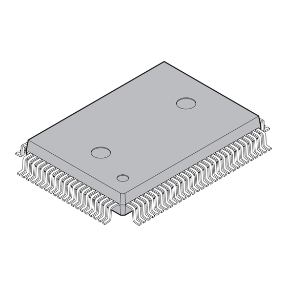
Page 30: Diagram Showing Package Dimensions
0.32±0.05 0.17±0.06 0.13(.005) (.013±.002) (.007±.002) 0.80±0.20 0.25±0.20 "A" (.010±.008) (.031±.008) (Stand off) 0.88±0.15 (.035±.006) Dimensions in mm (inches). 2002 FUJITSU LIMITED F100008S-c-5-5 Note: The values in parentheses are reference values. Please confirm the latest Package dimension by following URL. http://edevice.fujitsu.com/fj/DATASHEET/ef-ovpklv.html... - Page 31 0~8 ° "A" 0.50±0.20 0.25(.010) (.020±.008) 0.60±0.15 (.024±.006) 0.50(.020) 0.20±0.05 0.145±0.055 0.08(.003) (.008±.002) (.0057±.0022) Dimensions in mm (inches). Note: The values in parentheses are reference values. 2003 FUJITSU LIMITED F100007S-c-4-6 Please confirm the latest Package dimension by following URL. http://edevice.fujitsu.com/fj/DATASHEET/ef-ovpklv.html...
-
Page 32: Pin Assignment Diagram
CHAPTER 1 OUTLINE Pin Assignment Diagram This section presents the pin assignment diagram of MB90420G/425G series products. ■ Pin Assignment (QFP100) Figure 1.5-1 shows the pin assignment diagram for the plastic QFP100 type. Figure 1.5-1 Pin Assignment (QFP100) COM2 COM3 SEG0 P57/SGA SEG1... - Page 33 CHAPTER 1 OUTLINE ■ Pin Assignment (LQFP100) Figure 1.5-2 shows the pin assignment diagram for the plastic LQFP100 type. Figure 1.5-2 Pin Assignment (LQFP100) SEG0 P56/SGO/FRCK SEG1 P55/RX0 SEG2 P54/TX0 SEG3 DVss SEG4 P87/PWM2M3 SEG5 P86/PWM2P3 SEG6 P85/PWM1M3 SEG7 P84/PWM1P3 MB90420G/425G series DVcc SEG8...
-
Page 34: Description Of Pin Functions
CHAPTER 1 OUTLINE Description of Pin Functions This section describes the pin functions of MB90420G/425G series products. ■ Description of Pin Functions Table 1.6-1 describes the pin functions of MB90420G/425G series products. Table 1.6-1 Description of Pin Functions (1/4) Pin number I/O circuit Pin name Function... - Page 35 CHAPTER 1 OUTLINE Table 1.6-1 Description of Pin Functions (2/4) Pin number I/O circuit Pin name Function type LQFP General-purpose input/output port PPG0 Output pin for 16-bit PPG ch.0 TOT1 TOT output pin for 16-bit reload timer ch.1 General-purpose input/output port PPG1 Output pin for 16-bit PPG ch.1 TIN1...
- Page 36 CHAPTER 1 OUTLINE Table 1.6-1 Description of Pin Functions (3/4) Pin number I/O circuit Pin name Function type LQFP P60 to P67 General-purpose input/output port 36 to 39, 41 38 to 41, 43 to 44 to 46 AN0 to AN7 A/D converter input pin General-purpose input/output port INT1...
- Page 37 CHAPTER 1 OUTLINE Table 1.6-1 Description of Pin Functions (4/4) Pin number I/O circuit Pin name Function type LQFP General-purpose input/output port SGO output pin for sound generator FRCK Free-run timer clock input pin General-purpose input/output port SGA output pin for sound generator −...
-
Page 38: Types Of Input/Output Circuits
CHAPTER 1 OUTLINE Types of Input/Output Circuits This section describes the types of the input/output circuits for each pin. ■ Types of Input/Output Circuits Table 1.7-1 shows the types of input/output circuits for each pin. Table 1.7-1 Types of Input/Output Circuits (1/2) Type Circuit Description... - Page 39 CHAPTER 1 OUTLINE Table 1.7-1 Types of Input/Output Circuits (2/2) Type Circuit Description • CMOS output • LCDC output • Hysteresis input LCDC output Hysteresis input Standby control signal • CMOS output • Hysteresis input • Analog input Analog input Hysteresis input Standby control signal •...
-
Page 40: Precautions For Device Handling
CHAPTER 1 OUTLINE Precautions for Device Handling For device handling, pay special attention related to the following items: • Strictly observing the maximum voltage rating (for latch-up prevention) • Providing a stable supply voltage • Power-on • Handling unused pins •... - Page 41 CHAPTER 1 OUTLINE ■ Handling Unused Pins Leaving an unused input pin open may result in incorrect operation because of external noise. In these cases, pull-up or pull-down via a resistor of at least 2KΩ or more must be applied. An output pin that is not in use must be either set to output status and "open", or set to input status and handled as an input pin.
- Page 42 On this microcontroller, if in case the crystal oscillator breaks off or an external reference clock input stops while the PLL clock mode is selected, a self-oscillator circuit contained in the PLL may continue its operation at its self-running frequency. However, Fujitsu will not guarantee results of operations if such failure occurs.
-
Page 43: Chapter 2 Cpu
CHAPTER 2 CPU CHAPTER 2 This Chapter describes the CPU of the F MC-16LX. 2.1 Outline of CPU 2.2 Memory Space 2.3 Memory Map 2.4 Addressing 2.5 Allocation of Multiple-Byte Data in the Memory 2.6 Registers 2.7 Dedicated Registers 2.8 General-Purpose Register 2.9 Prefix Codes... -
Page 44: Outline Of Cpu
CHAPTER 2 CPU Outline of CPU The F MC-16LX CPU core is a 16-bit CPU designed for applications in which high- speed real-time processing is required, such as for various consumer devices and in vehicles. The F MC-16LX instruction set is designed for application in device controllers and is supporting a variety of control operations with high-speed and high efficiency processing. - Page 45 CHAPTER 2 CPU Note: MB90420G/425G series uses only single-chip mode, accessing only memory space of built-in ROM, built-in RAM and built-in circuits for peripherals.
-
Page 46: Memory Space
CHAPTER 2 CPU Memory Space MC-16LX CPU has a memory space of 16 Mbytes. The F MC-16LX CPU controls general-purpose data, program data and I/O data, all of which are allocated within the 16 Mbytes memory space. A part of the memory space is used for special applications, such as for extension intelligent I/O service (EI OS) descriptors, general-purpose registers and vector tables. - Page 47 CHAPTER 2 CPU ■ ROM Area ❍ Vector table area (Address: FFFC00 to FFFFFF • Used as vector tables for vector call instructions, interrupt vectors and reset vectors. • Assigned to the highest portion of ROM area for setting the start address of the corresponding routine as address data in the applicable vector table.
-
Page 48: Memory Map
CHAPTER 2 CPU Memory Map This section describes the memory map for the different types of MB90420G/425G series products. ■ Memory Map Figure 2.3-1 shows the memory map of MB90420G/425G series. Figure 2.3-1 Memory Map Single chip mode (using ROM mirror function) 000000 Peripheral area 0000C0... - Page 49 CHAPTER 2 CPU Notes: • If "no ROM mirror function" is selected, refer to "CHAPTER 24 ROM MIRROR FUNCTION SELECTION MODULE". • The upper 00 bank allows referencing ROM data in the FF bank as an image for effectively using the C compiler's small model. Because the FF bank's lower 16-bit address is set to the same value, the table in ROM can be referenced without using a far declaration with a pointer.
-
Page 50: Addressing
CHAPTER 2 CPU Addressing Both linear and bank address generation schemes are available. The linear scheme is used to directly specify all 24-bit addresses within the instruction. The bank scheme is used to directly specify upper 8-bit addresses via the bank register depending on how the data will be used and to specify the lower bit addresses with instructions. -
Page 51: Addressing With Linear Scheme
CHAPTER 2 CPU 2.4.1 Addressing with Linear Scheme There are two types of linear addressing: Directly addressing 24-bit addresses with an operand, and using the lower 24 bits of 32-bit general-purpose registers as address. ■ Specification with 24-bit Operand Figure 2.4-2 Example of Linear addressing (Specification with 24-bit Operand) JMPP 123456H Old program counter 452D... -
Page 52: Addressing With Bank Scheme
CHAPTER 2 CPU 2.4.2 Addressing with Bank Scheme When applying the bank scheme, the 16 Mbytes memory space is divided into 256 banks of 64 Kbytes each, and the bank address corresponding to each space is specified via a bank register. The upper 8 bits of the address are specified with the bank address and the lower 16 bits are specified with an instruction. - Page 53 CHAPTER 2 CPU Figure 2.4-4 Physical Address of Each Bank Register FFFFFF Program space FF0000 : PCB (Program counter bank register) 0FFFFF Additional space : ADB (Additional data bank register) 0F0000 0DFFFF User stack space 0D0000 : USB (User stack bank register) 0BFFFF Data space 0B0000...
-
Page 54: Allocation Of Multiple-Byte Data In The Memory
CHAPTER 2 CPU Allocation of Multiple-Byte Data in the Memory Multiple-byte data is written to memory sequentially starting from the lower address in sequence. For 32-bit data, first the lower 16 bits are transferred, then the upper 16 bits. If a reset signal is input immediately after writing the lower part of the data, the upper part of the data cannot be written. - Page 55 CHAPTER 2 CPU ■ Allocation of Multiple-Byte Data on the Stack Figure 2.5-3 shows the allocation of multiple-byte data on the stack. Figure 2.5-3 Allocation of Multiple-byte Data on the Stack PUSHW RW1, RW3 PUSHW (35A4 ) (6DF0 Address n RW1: 35A4 RW3: 6DF0 ■...
-
Page 56: Registers
CHAPTER 2 CPU Registers The F MC-16LX registers are roughly divided into two types: CPU-internal dedicated registers, and general-purpose registers in the built-in RAM. ■ Dedicated Register and General-Purpose Registers Dedicated registers consist of dedicated hardware in the CPU and their use is limited by the CPU architecture. -
Page 57: Dedicated Registers
CHAPTER 2 CPU Dedicated Registers The eleven types of dedicated registers in the CPU are listed below. • Accumulator (A) • User stack pointer (USP) • System stack pointer (SSP) • Processor status (PS) • Program counter (PC) • Direct page register (DPR) •... - Page 58 CHAPTER 2 CPU Table 2.7-1 Initial Value of Dedicated Registers Dedicated registers Initial value Accumulator (A) Unspecified User stack pointer (USP) Unspecified System stack pointer (SSP) Unspecified Processor status (PS) bit15 to bit13 bit12 bit8 bit7 bit0 - : Undefined X : Unspecified value Program counter (PC) Value stored in the reset vector (contents of address FFFFDC...
-
Page 59: Accumulator (A)
CHAPTER 2 CPU 2.7.1 Accumulator (A) The accumulator (A) consists of two 16-bit registers (AH and AL) to temporarily store operation results or other data items. The A register is used as a 32-/16-/8-bit register, for the purpose of executing a variety of operations between memory and other registers, or between AH and AL registers. - Page 60 CHAPTER 2 CPU ❍ Byte-based arithmetic operations of the accumulator When executing a byte-based arithmetic operation instruction on the contents of the AL register, the contents that the upper 8 bits of the AL register have before the operation are ignored, and the upper 8 bits of operation result are set all zeroes.
- Page 61 CHAPTER 2 CPU Figure 2.7-4 Example of accumulator (A) Transfers between AL and AH (8-bit Immediate Data, Code Extension) (Instruction to read long-word data from the address calculated as RW1 content + 8-bit offset, then writing the result to the A register MOVW A, 3000H Memory space Before execution...
-
Page 62: Stack Pointers (Usp, Ssp)
CHAPTER 2 CPU 2.7.2 Stack Pointers (USP, SSP) There are two types of stack pointers in the MB90420G/425G series: a user stack pointer (USP) and a system stack pointer (SSP). These are registers used to indicate the destination address in memory for data relocation or recovery when executing the PUSH instruction, POP instruction, or subroutines. - Page 63 CHAPTER 2 CPU Figure 2.7-7 Stack Operation Instructions and Stack Pointers PUSHW A if the S flag is set to 0 Before execution A624 F328 C6F326 S flag 1234 User stack is used because After execution A624 F326 the S flag is set to 0 S flag 1234 C6F326...
-
Page 64: Processor Status (Ps)
CHAPTER 2 CPU 2.7.3 Processor Status (PS) The processor status register (PS) consists of CPU control bits and a variety of bits indicating the CPU state. ■ Bit Configuration of Processor Status Register (PS) The PS register consists of three registers listed below. •... - Page 65 CHAPTER 2 CPU ■ Condition Code Register (PS: CCR) This register consists of 8 bits including bits representing operation result and the contents of data transfers as well as bits controlling the acceptance of interrupt requests. Figure 2.7-9 shows the bit configuration of the CCR register. For the status of the condition code register (CCR) after an instruction is executed, refer to the "Programming Manual".
- Page 66 CHAPTER 2 CPU ■ Register Bank Pointer (PS: RP) Used to indicate the start address in the general-purpose register bank currently used. This pointer is used to convert the actual address for general-purpose register addressing. Figure 2.7-10 shows the bit configuration for the register bank pointer (RP). Figure 2.7-10 Bit Configuration of Register Bank Pointer (RP) Initial value of bit15 bit14 bit13 bit12 bit11 bit10 bit9...
- Page 67 CHAPTER 2 CPU ■ Interrupt Level Mask Register (PS: ILM) The interrupt level mask register (ILM) is a 3-bit register used to indicate the interrupt level the CPU can accept. Figure 2.7-12 shows the bit configuration of the interrupt level mask register (ILM). For detailed information of the interrupt, refer to "CHAPTER 3 INTERRUPTS".
-
Page 68: Program Counter (Pc)
CHAPTER 2 CPU 2.7.4 Program Counter (PC) The program counter (PC) is a 16-bit counter that indicates the lower 16-bits of the address in memory at which the instruction code the CPU will execute next is stored. ■ Program Counter (PC) The address at which the instruction code that will be executed next by the CPU executed is stored consists of the upper 8 bits, specified by the program counter bank register (PCB), and the lower 16 bits specified by the program counter (PC). -
Page 69: Direct Page Register (Dpr)
CHAPTER 2 CPU 2.7.5 Direct Page Register (DPR) The direct page register (DPR) is an 8-bit register used to specify bit8 to bit15 (addr8 to addr15) at the operand address when an instruction applying the abbreviated direct addressing scheme is executed. ■... -
Page 70: Bank Registers (Pcb, Dtb, Usb, Ssb, Adb)
CHAPTER 2 CPU 2.7.6 Bank Registers (PCB, DTB, USB, SSB, ADB) The bank registers are used to specify the upper 8-bit address for bank scheme addressing. They consist of the five registers listed below. • Program counter bank register (PCB) •... -
Page 71: General-Purpose Register
CHAPTER 2 CPU General-Purpose Register The general-purpose register is a memory block located in RAM at the addresses , where 16 bits × 8 are allocated per bank. It may be used as either 000180 to 00037F general-purpose eight-bit register (byte register R0 to R7), 16-bit register (word register RW0 to RW7) or 32-bit register (long word register RL0 to RL7). - Page 72 CHAPTER 2 CPU ■ Register Bank The register bank consist of general-purpose registers (byte register R0 to R7, word register RW0 to RW7, long word register RL0 to RL3) used for a variety of operations and as pointers. The long word register is used as a linear pointer for directly accessing the entire memory space.
-
Page 73: Prefix Codes
CHAPTER 2 CPU Prefix Codes Placing a prefix code before an instruction partially changes the operation performed for the instruction. The MB90420G/425G series has three types of prefix codes: • bank select prefix (PCB, DTB, ADB, SPB) • common register bank prefix (CMR) •... - Page 74 CHAPTER 2 CPU Table 2.9-2 Instructions not Affected by Bank Select Prefix Instruction type Instruction Effect of bank select prefix MOVS MOVSW The bank register specified by the String instruction SCEQ SCWEQ operand is used irrespective of whether a prefix is present. FILS FILSW The user stack bank (USB) is used if...
- Page 75 CHAPTER 2 CPU ■ Common Register Bank Prefix (CMR) To facilitate the data exchange between multiple tasks, a method must be provided for easily accessing the same register bank regardless of the register bank pointer (RP). For this purpose, the F MC-16LX series provides a register bank that can be commonly used for each task, called the common bank.
- Page 76 CHAPTER 2 CPU ■ Flag Change Suppression Prefix (NCC) The flag change suppression prefix (NCC) is used to suppress unnecessary flag changes. Placing an NCC prefix before the instruction for which you want to suppress the flag change will prevent a flag change due to execution of the instruction. Changes can be suppressed for the flags T, N, Z, V and C.
- Page 77 CHAPTER 2 CPU ■ Restrictions on Prefix Codes The three restrictions listed below apply when using prefix codes. • No interrupt/hold request is accepted when a prefix code or an interrupt/hold suppress instruction is used. • The effect of a prefix code is delayed if the prefix is placed before an interrupt/hold instruction.
- Page 78 CHAPTER 2 CPU ❍ Delayed effect of prefix codes If, as shown in Figure 2.9-2, a prefix code is placed before an interrupt/hold suppress instruction, the prefix code becomes effective starting with the first instruction after the interrupt/ hold suppress instruction. Figure 2.9-2 Interrupt/hold Suppress Instruction and Prefix Code Interrupt/hold suppress instruction MOV ILM,#imm8...
-
Page 79: Chapter 3 Interrupts
CHAPTER 3 INTERRUPTS CHAPTER 3 INTERRUPTS This chapter describes the relationships between interrupts and the extended intelligent I/O service (EI OS). 3.1 Outline of Interrupts 3.2 Interrupt Sources and Interrupt Vectors 3.3 Interrupt Control Registers and Peripheral Functions 3.4 Hardware Interrupts 3.5 Software Interrupts 3.6 Interrupt by Extended Intelligent I/O Service (EI 3.7 Exception Processing Interrupts when Executing Undefined Instructions... -
Page 80: Outline Of Interrupts
CHAPTER 3 INTERRUPTS Outline of Interrupts MC-16LX has four types of interrupt functions for interrupting processing currently being performed and transfer control to a separately defined program if an event occurs. • Hardware interrupts • Software interrupts • Interrupts from the extended intelligent I/O service (EI •... - Page 81 CHAPTER 3 INTERRUPTS ■ Interrupt Operation MC-16LX has four types of interrupt functions for starting and resuming processing, as shown in Figure 3.1-1. Figure 3.1-1 Overall Operational Flow of Interrupt Processing START Main program Valid hardware interrupt request Interrupt start/processing String type for resuming instruction being...
-
Page 82: Interrupt Sources And Interrupt Vectors
CHAPTER 3 INTERRUPTS Interrupt Sources and Interrupt Vectors MC-16LX has functions corresponding to 256 types of interrupt sources. There are 256 interrupt vector tables allocated starting with the highest address in memory. The interrupt vectors are shared by all interrupts. Software interrupts may use all of the above interrupts (INT0 to INT256), but some of these interrupt vectors will then be shared by hardware interrupts and exception handling interrupts. - Page 83 CHAPTER 3 INTERRUPTS ■ Interrupt Sources and Interrupt Vectors/Interrupt Control Registers Table 3.2-2 shows the relationship between interrupt sources and the interrupt vectors/interrupt control registers (except for software interrupts). Table 3.2-2 Interrupt Sources and Interrupt Vectors/Interrupt Control Registers (1/2) Interrupt control Interrupt vector Priority register...
- Page 84 CHAPTER 3 INTERRUPTS Table 3.2-2 Interrupt Sources and Interrupt Vectors/Interrupt Control Registers (2/2) Interrupt control Interrupt vector Priority register Interrupt source Number Address Address Free-run timer cancel FFFF78 High ICR11 0000BB Sound generator FFFF74 Timebase timer FFFF70 ICR12 0000BC Watch timer (sub-clock) FFFF6C UART1 receive FFFF68...
-
Page 85: Interrupt Control Registers And Peripheral Functions
CHAPTER 3 INTERRUPTS Interrupt Control Registers and Peripheral Functions Interrupt control registers (ICR00 to ICR15) are located in the interrupt controller corresponding to the peripheral functions that use interrupt functions. This registers control the interrupt and extended intelligent I/O service (EI OS). - Page 86 CHAPTER 3 INTERRUPTS ■ Functions of Interrupt Control Registers The interrupt control registers (ICR) have the four functions listed below. • Setting the interrupt level for the corresponding peripheral function • Selecting whether the interrupt for the corresponding peripheral function is set to either normal interrupt or extended intelligent I/O service •...
-
Page 87: Interrupt Control Registers (Icr00 To Icr15)
CHAPTER 3 INTERRUPTS 3.3.1 Interrupt Control Registers (ICR00 to ICR15) The interrupt control registers correspond to the peripheral functions that use interrupt functions for controlling processing at interrupt request generation. The functions of these registers are slightly different depending on whether a write or a read operation is performed. - Page 88 CHAPTER 3 INTERRUPTS Figure 3.3-2 Interrupt Control Registers (ICR00 to ICR15) during Read Operations Read Operation Initial value Address 0000B0 - - 0 0 0 1 1 1 0000BF Interrupt level setting bit Interrupt level 0 (highest) Interrupt level (no interrupt) OS enable bit Interrupt sequence started when an interrupt occurs OS started when an interrupt occurs...
-
Page 89: Function Of Interrupt Control Registers
CHAPTER 3 INTERRUPTS 3.3.2 Function of Interrupt Control Registers The interrupt control registers (ICR00 to ICR15) consist of bits for the following four functions: • Interrupt level setting (IL2 to IL0) • Extended intelligent I/O service (EI OS) enable (ISE) •... - Page 90 CHAPTER 3 INTERRUPTS ■ Function of Interrupt Control Register ❍ Interrupt level setting bits (IL2 to IL0) Specify the interrupt level of the corresponding peripheral function. The interrupt level is initialized to level 7 (no interrupt) at reset. The interrupt level setting bits correspond to each interrupt level as shown in Table 3.3-2.
- Page 91 CHAPTER 3 INTERRUPTS Table 3.3-3 Relationship between EI OS Channel Selection Bits and Descriptor Addresses ICS3 ICS2 ICS1 ICS0 Selected channel Descriptor address 000100 000108 000110 000118 000120 000128 000130 000138 000140 000148 000150 000158 000160 000168 000170 000178 ❍ Extended intelligent I/O service (EI OS) status bits (S1, S0) These bits are read-only bits.
-
Page 92: Hardware Interrupts
CHAPTER 3 INTERRUPTS Hardware Interrupts Hardware interrupts are used to temporarily stop the execution of program that is being executed by the CPU in response to an interrupt request signal from a peripheral function and then transfer control to a user-defined interrupt handling program. The extended intelligent I/O service (EI OS) or an external interrupt may also be executed as a kind of hardware interrupt. - Page 93 CHAPTER 3 INTERRUPTS ■ Configuration for Hardware Interrupts The system configuration for handling hardware interrupts is divided into four types of elements, as shown in Table 3.4-1. To use hardware interrupts, the program must specify the location of these four configuration elements. Table 3.4-1 Configuration for Handling Hardware Interrupts Configuration element for handling hardware...
- Page 94 CHAPTER 3 INTERRUPTS ❍ Suppressing a hardware interrupts by interrupt suppress instructions The 10 types of hardware interrupt suppress instruction shown in Table 3.4-2 will suppress detection of hardware interrupt requests and ignore any such interrupt request. Even if a valid hardware interrupt request is issued when these instructions are being executed, interrupt handling is not executed until another type of instruction is executed.
-
Page 95: Hardware Interrupt Operation
CHAPTER 3 INTERRUPTS 3.4.1 Hardware Interrupt Operation This section describes the operation from generation of a hardware interrupt request to the completion of interrupt handling. ■ Starting of Hardware Interrupt Processing ❍ Operation of peripheral function (generating an interrupt request) A peripheral function that uses hardware interrupt requests has an interrupt request flag to indicate whether an interrupt request is present and an interrupt enable flag to enable or disable interrupt requests to the CPU. - Page 96 CHAPTER 3 INTERRUPTS ■ Hardware Interrupt Operation Figure 3.4-2 shows the operation from the generation of a hardware interrupt to when interrupt handling is completed. Figure 3.4-2 Operation of Hardware Interrupts Internal data bus PS, PC . . Microcode Check Comparator MC-16LX CPU Other peripheral...
-
Page 97: Operation Flow For Hardware Interrupts
CHAPTER 3 INTERRUPTS 3.4.2 Operation Flow for Hardware Interrupts If an interrupt request is generated from a peripheral function, the interrupt controller transfers the respective interrupt level to the CPU. If the CPU state allows for acceptance of interrupts, the instruction currently being executed is temporarily suspended to execute the interrupt handling routine or start the extended intelligent I/O service (EI OS). -
Page 98: Procedure For Using Hardware Interrupts
CHAPTER 3 INTERRUPTS 3.4.3 Procedure for Using Hardware Interrupts To use an hardware interrupt, the system stack area, peripheral function, and interrupt control register (ICR) must be specified in advance. ■ Procedure for Using Hardware Interrupts An example procedure for using hardware interrupts is shown in Figure 3.4-4. Figure 3.4-4 Procedure for Using Hardware Interrupts Start Setting the system stack area... -
Page 99: Multiple Interrupts
CHAPTER 3 INTERRUPTS 3.4.4 Multiple Interrupts For hardware interrupts, multiple interrupts are realized by setting different interrupt levels to a interrupt level setting bit (IL0, IL1, IL2) in the interrupt control register (ICR) for multiple interrupt requests from the peripheral function. Multiple starts are however not allowed in extended intelligent I/O services. - Page 100 CHAPTER 3 INTERRUPTS ■ Example of Multiple Interrupts In the following example for processing multiple interrupts, the timer interrupt has priority over A/ D converter interrupts: the interrupt level of the A/D converter is set to 2, and the timer interrupt level is set to 1.
-
Page 101: Time For Handling Hardware Interrupts
CHAPTER 3 INTERRUPTS 3.4.5 Time for Handling Hardware Interrupts The time until the interrupt handling routine starts the execution after a hardware interrupt request is generated is the time until the instruction currently being executed is completed plus the interrupt handling time. ■... - Page 102 CHAPTER 3 INTERRUPTS Table 3.4-3 Correction Values (Z) for the Interrupt Handling Time Address the stack pointer points to Correction value (Z) External 8 bits External even address External odd address Internal even address Internal odd address...
-
Page 103: Software Interrupts
CHAPTER 3 INTERRUPTS Software Interrupts Software interrupts have the function to transfer control from the program currently executed by the CPU to the interrupt handling program defined by the user when a software interrupt instruction (INT instruction) is executed. Hardware interrupts are disabled while a software interrupt is being executed. - Page 104 CHAPTER 3 INTERRUPTS ■ Operation for Software Interrupt Processing Figure 3.5-1 shows the operation performed from software interrupt generation to completion of interrupt handling. Figure 3.5-1 Operation of Software Interrupts Internal data bus PS, PC ... (2) Microcode Queue Fetch : Processor status register : Interrupt enable flag : Stack flag...
-
Page 105: Interrupt By Extended Intelligent I/O Service (Ei 2 Os)
CHAPTER 3 INTERRUPTS Interrupt by Extended Intelligent I/O Service (EI The extended intelligent I/O service (EI OS) is a function used to automatically transfer data between the peripheral function (I/O) and memory and generate a hardware interrupt when the data transfer is completed. ■... - Page 106 CHAPTER 3 INTERRUPTS ❍ Extended intelligent I/O service (EI OS) descriptor (ISD) This is a data item of 8 byte, which is located in the RAM at the addresses 000100 00017F , provided for 16 channels. It stores the transfer mode, I/O address and transfer counts, and buffer addresses.
-
Page 107: Extended Intelligent I/O Service (Ei 2 Os) Descriptor (Isd)
CHAPTER 3 INTERRUPTS 3.6.1 Extended Intelligent I/O Service (EI OS) Descriptor (ISD) The extended intelligent I/O service (EI OS) descriptor (ISD) is located in the internal and consists of 8 bytes × 16 channels. RAM at the addresses 000100 to 00017F ■... - Page 108 CHAPTER 3 INTERRUPTS Table 3.6-1 Relationship between Channel Number and Descriptor Address Channel Descriptor address 000100 000108 000110 000118 000120 000128 000130 000138 000140 000148 000150 000158 000160 000168 000170 000178...
-
Page 109: Registers Of The Extended Intelligent I/O Service (Ei 2 Os) Descriptor (Isd)
CHAPTER 3 INTERRUPTS 3.6.2 Registers of the Extended intelligent I/O Service (EI Descriptor (ISD) The extended intelligent I/O service (EI OS) descriptor (ISD) consists of the registers listed below. • Data counter (DCT) • I/O register address pointer (IOA) • Extended intelligent I/O service (EI OS) status register (ISCS) •... - Page 110 CHAPTER 3 INTERRUPTS Figure 3.6-4 Configuration of I/O Register Address Pointer (IOA) IOAH IOAL bit15 bit14 bit13 bit12 bit11 bit10 bit9 bit8 bit7 bit6 bit5 bit4 bit3 bit2 bit1 bit0 Initial value IOA A15 A14 A13 A12 A11 A10 A09 A08 A07 A06 A05 A04 A03 A02 A01 A00 XXXXXXXXXXXXXXXX R/W R/W R/W R/W R/W R/W R/W R/W R/W R/W R/W R/W R/W R/W R/W R/W R/W : Readable / writable...
- Page 111 CHAPTER 3 INTERRUPTS ■ Buffer Address Pointer (BAP) The buffer address pointer (BAP) is a register consisting of 24 bits. It is used to store the address for the next EI OS data transfer. A separate BAP is assigned for each EI OS channel;...
-
Page 112: Operation Of The Extended Intelligent I/O Service (Ei 2 Os)
CHAPTER 3 INTERRUPTS 3.6.3 Operation of the Extended intelligent I/O Service (EI If a peripheral function issues an interrupt request and the corresponding interrupt control register (ICR) is set to start EI OS, the CPU allows EI OS data transfer. After the data transfer is completed for the count specified, the system will automatically perform the hardware interrupt. -
Page 113: Procedure For Using The Extended Intelligent I/O Service (Ei 2 Os)
CHAPTER 3 INTERRUPTS 3.6.4 Procedure for Using the Extended Intelligent I/O Service Using the extended intelligent I/O service (EI OS) requires setting the system stack area, extended intelligent I/O service (EI OS) descriptor, peripheral function, and interrupt control register (ICR). ■... -
Page 114: Processing Time For The Extended Intelligent I/O Service (Ei 2 Os)
CHAPTER 3 INTERRUPTS 3.6.5 Processing Time for the Extended intelligent I/O Service The time for processing the extended intelligent I/O service (EI OS) depends on the following factors: • Setting of EI OS status register (ISCS) • Address (area) indicated by I/O register address pointer (IOA) •... - Page 115 CHAPTER 3 INTERRUPTS Table 3.6-3 Correction Values for Data Transfer during EI OS Execution Internal access External access I/O register address pointer B/even B/even 8/odd B/even Internal access Buffer address pointer B/even External access 8/odd B: Byte data transfer 8: External bus width for 8-bit word transfer Even: Even address word transfer Odd: Odd address word transfer ❍...
- Page 116 CHAPTER 3 INTERRUPTS ❍ When data transfer is ended by completion request from the peripheral function (I/O) If EI OS data transfer ends prematurely (ICR: S1, S0 = 11) because of receiving a completion request from the peripheral function (I/O), data transfer is not executed and a hardware interrupt is generated.
-
Page 117: Exception Processing Interrupts When Executing Undefined Instructions
CHAPTER 3 INTERRUPTS Exception Processing Interrupts when Executing Undefined Instructions MC-16LX handles undefined instructions by exception processing. Exception handling is basically performed in the same was as interrupt handling, i.e., the normal flow of processing is interrupted for starting exception handling if an exception event is detected at the instruction boundary. -
Page 118: Stack Operations Of Interrupt Handling
CHAPTER 3 INTERRUPTS Stack Operations of Interrupt Handling If an interrupt is accepted, the contents of the dedicated register is automatically swapped out to the system stack before processing branches to interrupt handling. Return from the stack is also automatically performed after interrupt handling is completed. - Page 119 CHAPTER 3 INTERRUPTS ■ Stack Area ❍ Allocation of the stack area The stack area is used for swapping out/returning the program counter (PC) as required for executing subroutine call instructions (CALL) and vector call instructions (CALLV) in addition to interrupt handling.
-
Page 120: Example Program For Interrupt Handling
CHAPTER 3 INTERRUPTS Example Program for Interrupt Handling An example program for interrupt handling is shown below. ■ Example Program for Interrupt Handling A coding example for an interrupt handling program that uses the external interrupt 0 (INT0) instruction is listed below. [Coding example] DDR1 000011H... - Page 121 CHAPTER 3 INTERRUPTS ;----------Vector setting---------------------------------------------------- VECT CSEG ABS=0FFH 0FFD0H ; Specify a vector for interrupt #11(0BH) ED_INT1 0FFDCH ; Reset vector setting START ; Set to single-chip mode VECT ENDS START...
- Page 122 CHAPTER 3 INTERRUPTS ■ Specification of Processing for the Sample Program of the Extended Intelligent I/O Service (EI 1. If H level is detected for the signal input to the INT0 pin, the extended intelligent I/O service OS) will start. 2.
- Page 123 CHAPTER 3 INTERRUPTS I:ICR00,#00001000B ; EI2OS channel 0, EI2OS enabled Interrupt level 0 (highest level) I:ELVR,#00000001B ; Use INT0 as "H" level request I:EIRR,#00H ; Clear INT0 interrupt source I:ENIR,#01H ; INT0 interrupt enabled ILM,#07H ; Set ILM within PS to level 7 CCR,#0E0H ;...
- Page 124 CHAPTER 3 INTERRUPTS...
-
Page 125: Chapter 4 Reset
CHAPTER 4 RESET CHAPTER 4 RESET This chapter describes the reset operation. 4.1 Outline of Reset Operation 4.2 Reset Sources and Oscillation Stabilization Wait Time 4.3 External Reset Pin 4.4 Reset Operation 4.5 Reset Source Bit 4.6 State of Each Pin after Reset... -
Page 126: Outline Of Reset Operation
CHAPTER 4 RESET Outline of Reset Operation If a reset source occurs, the CPU immediately interrupts the processing currently being executed and enters the reset clear wait state. After the reset is cleared, processing starts at the address indicated by the reset vector. There are six reset sources: •... - Page 127 CHAPTER 4 RESET ❍ Power-on reset Power-on reset is a reset that occurs when the power is turned on. The oscillation stabilization wait time is fixed to 2 oscillation clock cycles (2 /HCLK). After the oscillation stabilization wait time has elapsed, the reset operation is performed. ❍...
- Page 128 CHAPTER 4 RESET ❍ CPU operation detection resets In CPU operation detection resets, a reset is generated as soon as the CPU operation detection function counter overflows, if the CPU operation detection circuit clear bit (CL) in the low- voltage/CPU operation detection reset control register (LVRC) is not cleared to "0" within the specified time after power-on.
-
Page 129: Reset Sources And Oscillation Stabilization Wait Time
CHAPTER 4 RESET Reset Sources and Oscillation Stabilization Wait Time The MB90420G/425G series has six types of reset sources. The oscillation stabilization wait time at reset depends on the reset source. ■ Reset Sources and Oscillation Stabilization Wait Time Table 4.2-1 shows the reset sources and oscillation stabilization wait time of the MB90420G/ 425G series. - Page 130 CHAPTER 4 RESET Figure 4.2-1 shows the oscillation stabilization wait time when a power-on reset occurs. Figure 4.2-1 Oscillation Stabilization Wait Time for Power-on Reset /HCLK /HCLK CPU operation Oscillation Stabilization wait stabilization time of step-down wait time circuit HCLK: Oscillation clock frequency Table 4.2-2 Oscillation Stabilization Wait Time Depending on Clock Selection Register (CKSCR) Settings Oscillation stabilization wait time...
-
Page 131: External Reset Pin
CHAPTER 4 RESET External Reset Pin The external reset pin (RST pin) is a reset-input dedicated pin which generates an internal reset if "L" level is input. The MB90420G/425G series normally start reset operations based on the timing of the CPU operation clock, and only resets through external pins are performed asynchronously. -
Page 132: Reset Operation
CHAPTER 4 RESET Reset Operation If a reset is released, the target for reading mode data and the reset vector is selected based on the setting of the mode pins, and a mode fetch is performed. With this mode fetch operation, the CPU operation mode and the execution start address after the reset operation is completed are determined. - Page 133 CHAPTER 4 RESET ■ Mode Fetch If a reset is released, the CPU performs a hardware-based transfer of the reset vector and mode data to the relevant register inside the CPU core. Reset vector and mode data are allocated in a 4-byte area at the addresses FFFFDC to FFFFDF .
-
Page 134: Reset Source Bit
CHAPTER 4 RESET Reset Source Bit The source for reset generation can be identified by reading the watchdog timer control register (WDTC) and the low-voltage/CPU operation detection reset control register (LVRC). ■ Reset Source Bit Figure 4.5-1 shows the flip-flops corresponding to each reset source. The contents of the flip- flop can be obtained by reading the watchdog timer control register (WDTC). - Page 135 CHAPTER 4 RESET ■ Correspondence between Reset Source Bit and Reset Source The configuration of reset source bits in the watchdog timer control register (WDTC) is shown in Figure 4.5-2. The correspondence between the contents of reset source bits and reset sources is shown in Table 4.5-1.
- Page 136 CHAPTER 4 RESET ■ State of Reset Source Bits Figure 4.5-3 State of Reset Source Bits At power-on Bit clearing If low voltage is detected Bit clearing Vcc=4V PONR bit (Power-on or LVRF=1) ERST bit (External reset input, CPU operation detection) LVRF bit * 1 or 0 (Low voltage detection,...
- Page 137 CHAPTER 4 RESET ■ Notes on the Reset Source Bit ❍ If there are multiple reset sources at the same time If there are multiple reset sources at the same time, the corresponding reset source bits in the watchdog timer control register (WDTC) are set to "1". For example, if there is an external reset request from the RST pin at the same time as an overflow of the watchdog timer, the ERST and WRST bits are both set to "1".
-
Page 138: State Of Each Pin After Reset
CHAPTER 4 RESET State of Each Pin after Reset This section describes the state of each pin after reset. ■ State of Pins in Reset Mode The state of a pin while a reset is being in progress is specified by the setting of the mode pins (MD2 to MD0 are set to "011 "). -
Page 139: Chapter 5 Clock
CHAPTER 5 CLOCK CHAPTER 5 CLOCK This chapter describes the clock of the MB90420G/425G series. 5.1 Outline of Clock Unit 5.2 Block Diagram of the Clock Generation Section 5.3 Clock Selection Register (CKSCR) 5.4 Clock Mode 5.5 Oscillation Stabilization Wait Time 5.6 Connection of Resonator and External Clock... -
Page 140: Outline Of Clock Unit
CHAPTER 5 CLOCK Outline of Clock Unit The clock generation section controls operation of the internal clock that drives the CPU and peripheral functions. This internal clock is called the machine clock. One clock interval is called a machine cycle. The clock that uses this oscillation is called the oscillation clock, and the clock that uses the internal PLL oscillation is called the PLL clock. - Page 141 CHAPTER 5 CLOCK Note: With an operation voltage of 5 V, the oscillation clock can be 4 MHz. Note, however, that the CPU and peripheral functions are limited to a maximum operation frequency of 16 MHz. If multiplication is specified in such a way that the maximum operation frequency would be exceeded, devices will not operate normally.
- Page 142 CHAPTER 5 CLOCK Figure 5.1-1 Clock Supply Map Peripheral function Low-voltage detection circuit/CPU operation detection circuit Watchdog timer 16-bit PPG timer 0/1/2 PPG0 to 2 RX0(,1) Clock generation section CAN controller 0(/1) TX0(,1) Timebase timer SGA,SGO Clock 1 2 3 4 Sound generator generation circuit...
-
Page 143: Block Diagram Of The Clock Generation Section
CHAPTER 5 CLOCK Block Diagram of the Clock Generation Section The clock generation section consists of the following five blocks: • System clock generation circuit • PLL multiplication circuit • Clock selector • Clock selection register (CKSCR) • Oscillation stabilization wait time selector ■... - Page 144 CHAPTER 5 CLOCK ❍ System clock generation circuit Uses an externally connected resonator to create the oscillation clock (HCLK). Also, allows input from an external clock. ❍ Sub-clock generation circuit Uses an externally connected resonator to create the sub-clock (SCLK). Also, allows input from an external clock.
-
Page 145: Clock Selection Register (Ckscr)
CHAPTER 5 CLOCK Clock Selection Register (CKSCR) The clock selection register (CKSCR) is used to switch between the main clock and PLL clock, selecting the oscillation stabilization wait time, and the PLL clock’s multiplication ratio. ■ Configuration of the Clock Selection Register (CKSCR) Figure 5.3-1 shows the configuration of the clock selection register (CKSCR) configuration, and Table 5.3-1 describes the functions of each bit in the clock selection register (CKSCR). - Page 146 CHAPTER 5 CLOCK Table 5.3-1 Descriptions of Functions of Each Bit in the Clock Selection Register (CKSCR) (1/2) Bit name Function • Indicates whether the main clock or sub-clock is selected as the machine clock • The sub-clock is selected if this bit is set to "0", and the machine clock is selected if this bit is set to "1".
- Page 147 CHAPTER 5 CLOCK Table 5.3-1 Descriptions of Functions of Each Bit in the Clock Selection Register (CKSCR) (2/2) Bit name Function • Specifies whether the main clock or PLL clock is selected as the machine clock. • Selects the PLL clock if this bit is set to "0", or selects the main clock if it is set to "1".
-
Page 148: Clock Mode
CHAPTER 5 CLOCK Clock Mode The clock modes are main clock mode, PLL clock mode, and sub-clock mode. ■ Main Clock Mode, PLL Clock Mode, and Sub-clock Mode ❍ Main clock mode In main clock mode, a divide-by-2 frequency of the oscillation clock is used as operation clock of the CPU and peripheral functions, and the PLL clock is stopped. - Page 149 CHAPTER 5 CLOCK ❍ Transition from sub-clock mode to main clock mode If, in sub-clock mode, the clock selection register (CKSCR) SCS bit is set from "0" to "1", the operation switches from sub-clock mode to main clock mode after the main clock’s oscillation stabilization wait time has elapsed.
- Page 150 CHAPTER 5 CLOCK Figure 5.4-1 State Transition Diagram for the Machine Clock Selection Main MCS = 1 MCM = 1 Main SCS = 0 MCS = 1 (10) SCM = 1 MCS = 1 MCM = 1 CS1, CS0 = xx MCM = 1 SCS = 1 SCS = 0...
- Page 151 CHAPTER 5 CLOCK Note: The machine clock is initially set to the main clock (CKSCR MCS=1, SCS=1). If SCS and MCS are both set to "0", SCS has priority and the sub-clock is selected. When the sub-clock mode is switched to the PLL clock mode, be sure to set the oscillation stabilization wait time selection bits (WS1 and WS0) of the CKSCR register to "10 "...
-
Page 152: Oscillation Stabilization Wait Time
CHAPTER 5 CLOCK Oscillation Stabilization Wait Time If, when the power is turned on or the stop mode is canceled, clock mode switches from the sub-clock to the main clock or PLL clock, an oscillation stabilization wait time applies after oscillation starts because the oscillation clock is stopped. If the clock mode is switched from the main clock to the PLL clock or sub-clock, an oscillation stabilization wait time applies also after PLL oscillation starts. -
Page 153: Connection Of Resonator And External Clock
CHAPTER 5 CLOCK Connection of Resonator and External Clock The MB90420G/425G series has a built-in system clock generation circuit and generates a clock signal using an external resonator. It can also accept an external clock. ■ Connection of Resonator and External Clock ❍... - Page 154 CHAPTER 5 CLOCK...
-
Page 155: Chapter 6 Low-Power Consumption Mode
CHAPTER 6 LOW-POWER CONSUMPTION MODE CHAPTER 6 LOW-POWER CONSUMPTION MODE This chapter describes the low-power consumption mode. 6.1 Outline of Low-Power Consumption Mode 6.2 Block Diagram of Low-Power Consumption Control Circuit 6.3 Low-Power Consumption Mode Control Register (LPMCR) 6.4 CPU Intermittent Operation Mode 6.5 Standby Modes 6.6 State Transition Diagram 6.7 Pin States in Standby Mode and During Reset... -
Page 156: Outline Of Low-Power Consumption Mode
CHAPTER 6 LOW-POWER CONSUMPTION MODE Outline of Low-Power Consumption Mode This mode is one of the CPU operation modes, as shown below. The mode is selected by the operation clock selection and clock operation control. • Clock mode (PLL clock, main clock, and sub-clock) •... - Page 157 CHAPTER 6 LOW-POWER CONSUMPTION MODE ■ Clock Modes ❍ PLL clock mode Uses the PLL multiplication clock of the oscillation clock (HCLK) to drive the CPU and peripheral functions. ❍ Main clock mode Uses the divide-by-2 frequency of the oscillation clock (HCLK) to drive the CPU and peripheral functions.
- Page 158 CHAPTER 6 LOW-POWER CONSUMPTION MODE ■ Standby Mode In standby mode, to reduce the power consumption, the low-power consumption control circuit stops supplying the CPU with a clock signal (sleep mode), stops supplying the CPU and peripheral function with a clock signal (timebase timer mode), or stops the oscillation clock (stop mode).
-
Page 159: Block Diagram Of Low-Power Consumption Control Circuit
CHAPTER 6 LOW-POWER CONSUMPTION MODE Block Diagram of Low-Power Consumption Control Circuit The low-power consumption control circuit consists of seven blocks: • CPU intermittent operation selector • Standby control circuit • CPU clock control circuit • Peripheral clock control circuit •... - Page 160 CHAPTER 6 LOW-POWER CONSUMPTION MODE ❍ CPU intermittent operation selector This circuit is used to select the temporary stop clock count for CPU intermittent operation mode. ❍ Standby control circuit This circuit is used to control the CPU clock control circuit and peripheral clock control circuit to enter the low-power consumption mode or cancel it.
-
Page 161: Low-Power Consumption Mode Control Register (Lpmcr)
CHAPTER 6 LOW-POWER CONSUMPTION MODE Low-Power Consumption Mode Control Register (LPMCR) The low-power consumption mode control register (LPMCR) is used to enter or cancel the low-power consumption mode and set the CPU clock temporary stop cycle count in CPU intermittent operation mode. ■... - Page 162 CHAPTER 6 LOW-POWER CONSUMPTION MODE Table 6.3-1 Functional Description of Each Bit in the Low-power Consumption Mode Control Register (LPMCR) Bit name Function • Indicates a transition to stop mode. • Set this bit to "1" to enter the stop mode. •...
- Page 163 CHAPTER 6 LOW-POWER CONSUMPTION MODE The applicable pins are listed below. P01/SOT0/INT5, P02/SCK0/INT6, P04/SOT1, P05/SCK1/TRG, P06/PPG0/TOT1, P07/PPG1/TIN1, P10/PPG2, P11/TOT0/WOT ■ Accessing the Low-Power Consumption Mode Control Register Writing to the low-power consumption mode control register causes a transition to a low-power consumption mode (stop mode, sleep mode, timebase timer mode, or watch mode).
-
Page 164: Cpu Intermittent Operation Mode
CHAPTER 6 LOW-POWER CONSUMPTION MODE CPU Intermittent Operation Mode The CPU intermittent operation mode reduces the power consumption by maintaining high-speed operation for the external bus and peripheral functions while the CPU operates in intermittent operation mode. ■ CPU Intermittent Operation Mode In the CPU intermittent operation mode, the internal bus cycle start is delayed by stopping the clock supply to the CPU for the time specified for the individual instruction when accessing a register, built-in memory (ROM, RAM), I/O, peripheral function, or external bus. -
Page 165: Standby Modes
CHAPTER 6 LOW-POWER CONSUMPTION MODE Standby Modes The standby modes consist of the sleep (PLL sleep, main sleep, and sub-sleep), clock, and stop modes. ■ Operation in Standby Mode Table 6.5-1 shows the operation states in standby mode. Table 6.5-1 Operation States in Standby Mode Transition Machine Cancel... -
Page 166: Sleep Mode
CHAPTER 6 LOW-POWER CONSUMPTION MODE 6.5.1 Sleep Mode In sleep mode, the CPU operation clock stops and functions other CPU operations are resumed. Specifying a transition to sleep mode via the low-power consumption mode control register (LPMCR) changes the operation state to PLL sleep mode if the PLL clock mode is set;... - Page 167 CHAPTER 6 LOW-POWER CONSUMPTION MODE ❍ Return by interrupt When in sleep mode an interrupt with a level of 7 or higher occurs, e.g. from a peripheral circuit, sleep mode is canceled. After the sleep mode is canceled, the same processing as for a normal interrupt is performed.
-
Page 168: Timebase Timer Mode
CHAPTER 6 LOW-POWER CONSUMPTION MODE 6.5.2 Timebase Timer Mode The timebase timer mode is used to stop operations other than the operation of the oscillator, timebase timer, and watch timer. All functions except for the timebase timer and watch timer are stopped. ■... - Page 169 CHAPTER 6 LOW-POWER CONSUMPTION MODE ■ Canceling Timebase Timer Mode The low-power consumption control circuit is used to cancel the timer-base timer mode when a reset or an interrupt occurs. ❍ Return by reset Reset initializes to main clock mode. ❍...
-
Page 170: Watch Mode
CHAPTER 6 LOW-POWER CONSUMPTION MODE 6.5.3 Watch Mode This mode is used to stop operations other than operations of the sub-clock and watch timer. Most chip functions are stopped in this mode. This mode is only available for the MB90F423GC, MB90F428GC, MB90423GC, MB90427GC, MB90428GC series. - Page 171 CHAPTER 6 LOW-POWER CONSUMPTION MODE ■ Canceling Watch Mode The low-power consumption control circuit is used to cancel watch mode when a reset or an interrupt occurs. ❍ Return by reset Canceling the watch mode by a reset causes a transition to the oscillation stabilization wait reset state after the watch mode is canceled.
-
Page 172: Stop Mode
CHAPTER 6 LOW-POWER CONSUMPTION MODE 6.5.4 Stop Mode The stop mode is used to stop the oscillator and stop all functions. It allows retaining the data with the lowest power consumption possible. ■ Transition to Stop Mode Setting the low-power consumption mode control register (LPMCR) STP bit to "1" causes a transition to the stop mode. - Page 173 CHAPTER 6 LOW-POWER CONSUMPTION MODE ■ Canceling Stop Mode The low-power consumption control circuit is used to cancel the stop mode when a reset or interrupt occurs. At return from stop mode, since the operation clock has stopped, the low- power consumption control circuit changes to the oscillation stabilization wait state and then cancels the stop mode.
-
Page 174: State Transition Diagram
CHAPTER 6 LOW-POWER CONSUMPTION MODE State Transition Diagram Figure 6.6-1 shows the transition diagram for the operation mode and the transition conditions for the MB90420G/425G series. ■ State Transition Diagram Figure 6.6-1 State Transition Diagram External reset, watchdog timer reset, CPU operation detection reset, software reset Power applied Power voltage lowered... - Page 175 CHAPTER 6 LOW-POWER CONSUMPTION MODE ■ Operation States of the Low-Power Consumption Mode Table 6.6-1 shows the operation states of the low-power consumption mode. Table 6.6-1 Operation States of the Low-power Consumption Mode timebase Main Sub- Clock Operation state Peripheral Watch timer clock...
-
Page 176: Pin States In Standby Mode And During Reset
CHAPTER 6 LOW-POWER CONSUMPTION MODE Pin States in Standby Mode and During Reset This section shows the pin states in standby mode and during reset for each memory access mode. ■ Pin States in Single-Chip Mode Table 6.7-1 shows the pin states in single-chip mode. Table 6.7-1 Pin States in Single-chip Mode Standby mode Stop mode/watch mode/timebase... - Page 177 CHAPTER 6 LOW-POWER CONSUMPTION MODE Note: To set a pin to high-impedance when the pin is shared by a peripheral function and a port in stop mode, watch mode, or timebase timer mode, disable the output of peripheral functions, and set the STP bit to "1"...
-
Page 178: Notes On Using The Low-Power Consumption Mode
CHAPTER 6 LOW-POWER CONSUMPTION MODE Notes on Using the Low-Power Consumption Mode Pay special attention on the following items when using the low-power consumption mode: • Transition to standby mode and interrupts • Notes on Transition to Standby Mode • Canceling the standby mode by interrupt •... - Page 179 CHAPTER 6 LOW-POWER CONSUMPTION MODE ■ Canceling the Standby Mode by an Interrupt In sleep mode, timebase timer mode, or stop mode, the standby mode is canceled if a peripheral function generates an interrupt request with an interrupt level of 7 or higher. Whether the CPU accepts the interrupt does not matter.
- Page 180 CHAPTER 6 LOW-POWER CONSUMPTION MODE In PLL stop mode, the main clock and PLL multiplication circuit stop. During recovery from PLL stop mode, it is necessary to allot the main clock oscillation stabilization wait time and PLL clock oscillation stabilization wait time. The oscillation stabilization wait times for the main clock and PLL clock are counted simultaneously according to the value specified in the oscillation stabilization wait time selection bits (CKSCR: WS1, WS0) in the clock selection register.
- Page 181 CHAPTER 6 LOW-POWER CONSUMPTION MODE (2) Define the standby mode transition instruction using _asm statements and insert two NOP and JMP instructions after that instruction. Example: _asm(" MOVI: _IO_LPMCR,#H’58); /* Set LPMCR SLP bit to "1" */ _asm(" NOP"); _asm(" NOP"); _asm("...
- Page 182 CHAPTER 6 LOW-POWER CONSUMPTION MODE...
-
Page 183: Chapter 7 Mode Settings
CHAPTER 7 MODE SETTINGS CHAPTER 7 MODE SETTINGS This chapter describes the operation mode and memory access mode. 7.1 Setting the Mode 7.2 Mode pins (MD2 to MD0) 7.3 Mode Data... -
Page 184: Setting The Mode
CHAPTER 7 MODE SETTINGS Setting the Mode MC-16LX provides several modes with respect to access methods and access areas. Each mode can be set by setting mode pins during a reset and fetching mode data in a mode fetching operation. ■... -
Page 185: Mode Pins (Md2 To Md0)
CHAPTER 7 MODE SETTINGS Mode pins (MD2 to MD0) The mode pins are three external pins, MD2 to MD0, which are used to specify how to acquire the reset vector and mode data. ■ Mode Pins (MD2 to MD0) The mode pins are used to select whether the external or internal data bus is used to read the reset vector and for selecting the bus width during selection of the external data bus. -
Page 186: Mode Data
CHAPTER 7 MODE SETTINGS Mode Data The mode data, which is used to specify the operation during the reset sequence, is located in the memory at FFFFDF . The mode data is automatically loaded into the CPU with a mode fetch operation. ■... - Page 187 CHAPTER 7 MODE SETTINGS Figure 7.3-2 Relationship between access Area and Physical Address in Single-chip Mode If the ROM mirroring function is selected : No access : Internal access "#x depending on product type" indicates an address specified depending on the product type. ■...
- Page 188 CHAPTER 7 MODE SETTINGS...
-
Page 189: Chapter 8 I/O Ports
CHAPTER 8 I/O PORTS CHAPTER 8 I/O PORTS This chapter describes the functions and operation of the I/O ports. 8.1 I/O Ports 8.2 Assignment of Registers and Pins Shared with External Pins 8.3 Port 0 8.4 Port 1 8.5 Port 3 8.6 Port 4 8.7 Port 5 8.8 Port 6... -
Page 190: I/O Ports
CHAPTER 8 I/O PORTS I/O Ports The I/O ports are used as general-purpose input/output ports (parallel I/O ports). The number of ports for the MB90420G/425G series is 9 (58 pins). Each port is used both for peripheral functions and for providing input/output pins. ■... - Page 191 CHAPTER 8 I/O PORTS Table 8.1-1 shows the functions of each port. Table 8.1-1 Port Functions Type Port Type of Function bit7 bit6 bit5 bit4 bit3 bit2 bit1 bit0 name name input output P00/SIN0/ General-purpose INT4 input/output port Port 0 PPG1 PPG0 SCK1...
-
Page 192: Assignment Of Registers And Pins Shared With External Pins
CHAPTER 8 I/O PORTS Assignment of Registers and Pins Shared with External Pins The registers related to I/O port setting are listed below. ■ I/O Port Registers Table 8.2-1 shows the port registers. Table 8.2-1 Port Registers Register name Read/write Address Initial value Port 0 data register (PDR0) -
Page 193: Port 0
CHAPTER 8 I/O PORTS Port 0 Port 0 is a general-purpose input/output port and also used for input/output of the peripheral functions. For each pin, use for a peripheral function or as port is switched in units of individual bits. This section mainly describes the function of this port as a general-purpose input/output port and indicates the configuration, pins, and block diagrams of pins and registers for Port 0. - Page 194 CHAPTER 8 I/O PORTS ■ Pin Block Diagram for Port 0 Figure 8.3-1 shows the pin block diagram for Port 0. Figure 8.3-1 Pin Block Diagram for Port 0 Peripheral function output Peripheral function input Peripheral function output enabled PDR (Port data register) PDR read Output latch...
-
Page 195: Port 0 Registers (Pdr0, Ddr0)
CHAPTER 8 I/O PORTS 8.3.1 Port 0 registers (PDR0, DDR0) This section describes the registers for Port 0. ■ Function of Port 0 Register ❍ Port 0 data register (PDR0) The PDR0 register indicates the pin states. ❍ Port 0 direction register (DDR0) The DDR0 register is used to set the pin input/output direction for each bit. -
Page 196: Description Of Port 0 Operation
CHAPTER 8 I/O PORTS 8.3.2 Description of Port 0 Operation This section describes the operation of Port 0. ■ Operation of Port 0 ❍ Operation as an output port With the corresponding DDR0 register bit set to "1", the port works as an output port. When used as an output port, any data written to the PDR0 register is retained in the PDR output latch and then output to the pins as is. - Page 197 CHAPTER 8 I/O PORTS ❍ Reset operation At CPU reset, the value of the DDR0 register is initialized to "0". Thus, all the output buffers are set to "OFF" (input port) and the pins are set to "high-impedance". In a reset operation, the PDR0 register is not initialized. Therefore, if used as an output port, set the output data in the PDR0 register and then set the corresponding DDR0 register to output.
-
Page 198: Port 1
CHAPTER 8 I/O PORTS Port 1 Port 1 is used as both a general-purpose input/output port and for peripheral function input/output. The use of each pin for a peripheral function or as port is switched in units of individual bits. This section mainly describes the function of this port as a general-purpose input/output port and indicates the configuration, pins, and block diagrams of pins and registers for Port 1. - Page 199 CHAPTER 8 I/O PORTS ■ Pin Block Diagram for Port 1 Figure 8.4-1 shows the pin block diagram for Port 1. Figure 8.4-1 Pin Block Diagram for Port 1 Peripheral function output Peripheral function input Peripheral function output enabled PDR (Port data register) PDR read Output latch...
-
Page 200: Port 1 Registers (Pdr1, Ddr1)
CHAPTER 8 I/O PORTS 8.4.1 Port 1 Registers (PDR1, DDR1) This section describes the registers for Port 1. ■ Functions of Port 1 Registers ❍ Port 1 data register (PDR1) The PDR1 register indicates the pin states. ❍ Port 1 direction register (DDR1) The DDR1 register is used to set the pin input/output direction for each bit. -
Page 201: Description Of Port 1 Operation
CHAPTER 8 I/O PORTS 8.4.2 Description of Port 1 Operation This section describes the operation of Port 1. ■ Operation of Port 1 ❍ Operation as an Output Port With the corresponding DDR1 register bit set to "1", the port works as an output port. When used as an output port, if data is written to the PDR1 register, it is retained in the PDR output latch and then output to the pins as is. - Page 202 CHAPTER 8 I/O PORTS ❍ Reset operation At CPU reset, the DDR1 register value is cleared. Thus, all the output buffers are set to "OFF" (input port) and the pins are set to "high-impedance". In a reset operation, the PDR1 register is not initialized. Therefore, if used as an output port, set the output data in the PDR1 and then set the corresponding DDR1 register to "1".
-
Page 203: Port 3
CHAPTER 8 I/O PORTS Port 3 Port 3 is a general-purpose input/output port that is also used as peripheral function input/output. The use of each pin for a peripheral function or as port is switched in units of individual bits. This section mainly describes the function of this port as a general-purpose input/output port and indicates the configuration, pins, and block diagrams of pins and registers for Port 3. - Page 204 CHAPTER 8 I/O PORTS ■ Pin Block Diagram for Port 3 Figure 8.5-1 shows the pin block diagram for Port 3. Figure 8.5-1 Pin Block Diagram for Port 3 Peripheral function output Peripheral function output enabled PDR (Port data register) PDR read Output latch PDR write...
-
Page 205: Port 3 Registers (Pdr3, Ddr3)
CHAPTER 8 I/O PORTS 8.5.1 Port 3 Registers (PDR3, DDR3) This section describes the registers for Port 3. ■ Function of Port 3 Registers ❍ Port 3 data register (PDR3) The PDR3 register indicates the pin states. ❍ Port 3 direction register (DDR3) The DDR3 register is used to set the pin input/output direction for each bit. -
Page 206: Description Of Port 3 Operation
CHAPTER 8 I/O PORTS 8.5.2 Description of Port 3 Operation This section describes the operation of Port 3. ■ Operation of Port 3 ❍ Operation as an output port With the corresponding DDR3 register bit set to "1", the port works as an output port. When used as an output port, if data is written to the PDR3 register, it is retained in the PDR output latch and then output to the pins as is. - Page 207 CHAPTER 8 I/O PORTS ❍ Operation for the stop and timebase timer modes When a transition to the stop mode or timebase timer mode occurs, and the low-power consumption mode control register’s pin state specification bit (SPL in LPMCR) is "1", the pins are set to "high-impedance".
-
Page 208: Port 4
CHAPTER 8 I/O PORTS Port 4 Port 4 is a general-purpose input/output port that is also used as peripheral function input/output. The use of each pin for a peripheral function or as port is switched in units of individual bits. This section mainly describes the function of this port as a general-purpose input/output port and indicates the configuration, pins, and block diagrams of pins and registers for Port 4. - Page 209 CHAPTER 8 I/O PORTS ■ Pin Block Diagram for Port 4 Figure 8.6-1 shows the pin block diagram for Port 4. Figure 8.6-1 Pin Block Diagram for Port 4 Peripheral function output Peripheral function output enabled PDR (Port data register) PDR read Output latch PDR write...
-
Page 210: Port 4 Registers (Pdr4, Ddr4)
CHAPTER 8 I/O PORTS 8.6.1 Port 4 Registers (PDR4, DDR4) This section describes the registers for Port 4. ■ Function of Port 4 Registers ❍ Port 4 data register (PDR4) The PDR4 register indicates the pin states. ❍ Port 4 direction register (DDR4) The DDR4 register is used to set the pin input/output direction for each bit. -
Page 211: Description Of Port 4 Operation
CHAPTER 8 I/O PORTS 8.6.2 Description of Port 4 Operation This section describes the operation of Port 4. ■ Operation of Port 4 ❍ Operation as an Output Port With the corresponding DDR4 register bit set to "1", the port works as an output port. When used as an output port, data is written to the PDR4 register, retained in the PDR output latch, and then output to the pins as is. - Page 212 CHAPTER 8 I/O PORTS ❍ Operation for the stop and timebase timer modes When a transition to the stop mode or timebase timer mode occurs, and the low-power consumption mode control register’s pin state specification bit (SPL in LPMCR) is "1", the pins are set to "high-impedance".
-
Page 213: Port 5
CHAPTER 8 I/O PORTS Port 5 Port 5 is a general-purpose input/output port that is also used as peripheral function input/output. The use of each pin for a peripheral function or as port is switched in units of individual bits. This section mainly describes the function of this port as a general-purpose input/output port and indicates the configuration, pins, and block diagrams of pins and registers for Port 5. - Page 214 CHAPTER 8 I/O PORTS Note: For the circuit type, refer to Section "1.7 Types of Input/Output Circuits". ■ Pin Block Diagram for Port 5 Figure 8.7-1 shows the pin block diagram for Port 5. Figure 8.7-1 Pin Block Diagram for Port 5 Peripheral function output Peripheral function input Peripheral function output enabled...
-
Page 215: Port 5 Registers (Pdr5, Ddr5)
CHAPTER 8 I/O PORTS 8.7.1 Port 5 Registers (PDR5, DDR5) This section describes the registers for Port 5. ■ Functions of Port 5 Registers ❍ Port 5 data register (PDR5) The PDR5 register indicates the pin states. ❍ Port 5 direction register (DDR5) The DDR5 register is used to set the pin input/output direction for each bit. -
Page 216: Description Of Port 5 Operation
CHAPTER 8 I/O PORTS 8.7.2 Description of Port 5 Operation This section describes the operation of Port 5. ■ Operation of Port 5 ❍ Operation as an output port With the corresponding DDR5 register bit set to "1", the port works as an output port. When used as an output port, if data is written to the PDR5 register, it is retained in the PDR output latch and then output to the pins as is. - Page 217 CHAPTER 8 I/O PORTS ❍ Reset operation At CPU reset, the DDR5 register value is cleared. Thus, all the output buffers are set to "OFF" (input port), and the pins are set to "high-impedance". In a reset operation, the PDR5 register is not initialized. Therefore, if used as an output port, set the output data in the PDR5 register and then set the corresponding DDR5 register to "1".
-
Page 218: Port 6
CHAPTER 8 I/O PORTS Port 6 Port 6 is a general-purpose input/output port that is also used as peripheral function input/output. The use of each pin for a peripheral function or as port is switched in units of individual bits. This section mainly describes the function of this port as a general-purpose input/output port and indicates the configuration, pins, and block diagrams of pins and registers for Port 6. - Page 219 CHAPTER 8 I/O PORTS ■ Pin Block Diagram for Port 6 Figure 8.8-1 shows the pin block diagram for Port 6. Figure 8.8-1 Pin Block Diagram for Port 6 ADER Analog input PDR (Port data register) PDR read Output latch PDR write DDR (Port direction register) Direction...
-
Page 220: Port 6 Registers (Pdr6, Ddr6, Ader)
CHAPTER 8 I/O PORTS 8.8.1 Port 6 Registers (PDR6, DDR6, ADER) This section describes the registers for Port 6. ■ Functions of Port 6 Registers ❍ Port 6 data register (PDR6) The PDR6 register indicates the pin states. ❍ Port 6 direction register (DDR6) The DDR6 register is used to set the pin input/output direction for each bit. - Page 221 CHAPTER 8 I/O PORTS Table 8.8-3 Functions of Port 6 Registers Register Data At reading At writing Address Initial value name With DDR=0, high-impedance Pin state: state is assumed. "L" level Port 6 data With DDR=1, "L" level is output. register 000006 XXXXXXXX...
-
Page 222: Description Of Port 6 Operation
CHAPTER 8 I/O PORTS 8.8.2 Description of Port 6 Operation This section describes the operation of Port 6. ■ Operation of Port 6 ❍ Operation as an output port With the corresponding DDR6 register bit set to "1", the port works as an output port. When used as an output port, if data is written to the PDR6 register, it is retained in the PDR output latch and then output to the pins as is. - Page 223 CHAPTER 8 I/O PORTS ❍ Operation for the stop and timebase timer modes When a transition to the stop mode or timebase timer mode occurs, and the low-power consumption mode control register’s pin state specification bit (SPL in LPMCR) is "1", the pins are set to "high-impedance".
-
Page 224: Port 7
CHAPTER 8 I/O PORTS Port 7 Port 7 is a general-purpose input/output port that is also used as peripheral function input/output. The use of each pin for a peripheral function or as port is switched in units of individual bits. This section mainly describes the function of this port as a general-purpose input/output port and indicates the configuration, pins, and block diagrams of pins and registers for Port 7. - Page 225 CHAPTER 8 I/O PORTS ■ Pin Block Diagram for Port 7 Figure 8.9-1 shows the pin block diagram for Port 7. Figure 8.9-1 Pin Block Diagram for Port 7 Peripheral function output Peripheral function output enabled PDR(Port data register) PDR read Output latch PDR write DDR(Port direction register)
-
Page 226: Port 7 Registers (Pdr7, Ddr7)
CHAPTER 8 I/O PORTS 8.9.1 Port 7 Registers (PDR7, DDR7) This section describes the registers for Port 7. ■ Functions of Port 7 Registers ❍ Port 7 data register (PDR7) The PDR7 register indicates the pin states. ❍ Port 7 direction register (DDR7) The DDR7 register is used to set the pin input/output direction for each bit. -
Page 227: Description Of Port 7 Operation
CHAPTER 8 I/O PORTS 8.9.2 Description of Port 7 Operation This section describes the operation of Port 7. ■ Operation of Port 7 ❍ Operation as an output port With the corresponding DDR7 register bit set to "1", the port works as an output port. When used as an output port, if data is written to the PDR7 register, it is retained in the PDR output latch and then output to the pins as is. - Page 228 CHAPTER 8 I/O PORTS Notes: • The pin state is not initialized to "L" output by a reset, but this output is output regardless of the PDR7/DDR7 register. Unless this "L" output is cleared, port 7 pins cannot be used as the resource output or the general-purpose port.
-
Page 229: Port 8
CHAPTER 8 I/O PORTS 8.10 Port 8 Port 8 is a general-purpose input/output port that is also used as peripheral function input/output. The use of each pin for a peripheral function or as port is switched in units of individual bits. This section mainly describes the function of this port as a general-purpose input/output port and indicates the configuration, pins, and block diagrams of pins and registers for Port 8. - Page 230 CHAPTER 8 I/O PORTS ■ Pin Block Diagram for Port 8 Figure 8.10-1 shows the pin block diagram for port 8. Figure 8.10-1 Pin Block Diagram for Port 8 Peripheral function output Peripheral function output enabled PDR(Port data register) PDR read Output latch PDR write DDR(Port direction register)
-
Page 231: Port 8 Registers (Pdr8, Ddr8)
CHAPTER 8 I/O PORTS 8.10.1 Port 8 Registers (PDR8, DDR8) This section describes the registers for port 8. ■ Functions of Port 8 Registers ❍ Port 8 data register (PDR8) The PDR8 register indicates the pin states. ❍ Port 8 direction register (DDR8) The DDR8 register is used to set the pin input/output direction for each bit. -
Page 232: Description Of Port 8 Operation
CHAPTER 8 I/O PORTS 8.10.2 Description of Port 8 Operation This section describes the operation of Port 8. ■ Operation of Port 8 ❍ Operation as an output port With the corresponding DDR8 register bit set to "1", the port works as an output port. When used as an output port, if data is written to the PDR8 register, it is retained in the PDR output latch and then output to the pins as is. - Page 233 CHAPTER 8 I/O PORTS Notes: • The pin state is not initialized to "L" output by a reset, but this output is output regardless of the PDR8/DDR8 register. Unless this "L" output is cleared, port 8 pins cannot be used as the resource output or the general-purpose port.
-
Page 234: Port 9
CHAPTER 8 I/O PORTS 8.11 Port 9 Port 9 is a general-purpose input/output port that is also used for peripheral function input/output. The use of each pin for a peripheral function or as port is switched in units of individual bits. This section mainly describes the function of this port as a general-purpose input/output port and indicates the configuration, pins, and block diagrams of pins and registers for Port 9. - Page 235 CHAPTER 8 I/O PORTS ■ Pin Block Diagram for Port 9 Figure 8.11-1 shows the pin block diagram for Port 9. Figure 8.11-1 Pin Block Diagram for Port 9 Peripheral function output Peripheral function output enabled PDR (Port data register) PDR read Output latch PDR write...
-
Page 236: Functions Of Port 9 Registers (Pdr9, Ddr9)
CHAPTER 8 I/O PORTS 8.11.1 Functions of Port 9 Registers (PDR9, DDR9) This section describes the registers for port 9. ■ Function of Port 9 Registers ❍ Port 9 data Register (PDR9) The PDR9 register indicates the pin states. ❍ Port 9 Direction Register (DDR9) The DDR9 register is used to set the pin input/output direction for each bit. -
Page 237: Description Of Port 9 Operation
CHAPTER 8 I/O PORTS 8.11.2 Description of Port 9 Operation This section describes the operation of port 9. ■ Operation of Port 9 ❍ Operation as an output port With the corresponding DDR9 register bit set to "1", the port works as an output port. When used as an output port, if data is written to the PDR9 register, it is retained in the PDR output latch and then output to the pins as is. - Page 238 CHAPTER 8 I/O PORTS ❍ Operation for the stop and timebase timer modes When a transition to the stop mode or timebase timer mode occurs, and the low-power consumption mode control register’s pin state specification bit (SPL in LPMCR) is "1", the pins are set to "high-impedance".
-
Page 239: Example Program For I/O Port
CHAPTER 8 I/O PORTS 8.12 Example Program for I/O Port An example program that uses the I/O port is shown below. ■ Example Program for I/O Port ❍ Specification of processing On ports 0 and 1, all 7-segment LEDs (8-segment if Dp is included) are on. The P00 pin corresponds to the LED’s common anode pin, and the P10 to P17 pins correspond to the segment pins. - Page 240 CHAPTER 8 I/O PORTS...
-
Page 241: Chapter 9 Watchdog Timer/Timebase Timer/Watch Timer (Sub-Clock)
CHAPTER 9 WATCHDOG TIMER/TIMEBASE TIMER/WATCH TIMER (SUB-CLOCK) CHAPTER 9 WATCHDOG TIMER/TIMEBASE TIMER/ WATCH TIMER (SUB-CLOCK) This chapter describes the functions and operation of the watchdog timer, timebase timer, and watch timer (used as sub-clock). 9.1 Outline of Watchdog Timer/Timebase Timer/Watch Timer 9.2 Block Diagrams of Watchdog Timer/Timebase Timer/Watch Timer 9.3 List of Registers for Watchdog Timer/Timebase Timer/Watch Timer 9.4 Operation of Watchdog Timer/Timebase Timer/Watch Timer... -
Page 242: Outline Of Watchdog Timer/Timebase Timer/Watch Timer
CHAPTER 9 WATCHDOG TIMER/TIMEBASE TIMER/WATCH TIMER (SUB-CLOCK) Outline of Watchdog Timer/Timebase Timer/Watch Timer The circuit configuration of the watchdog timer, timebase timer, and watch timer is shown below. • Watchdog timer: watchdog counter, control register and watchdog reset circuit • Timebase timer: 18-bit timer, circuit to generate interrupts in intervals •... -
Page 243: Block Diagrams Of Watchdog Timer/Timebase Timer/Watch Timer
CHAPTER 9 WATCHDOG TIMER/TIMEBASE TIMER/WATCH TIMER (SUB-CLOCK) Block Diagrams of Watchdog Timer/Timebase Timer/Watch Timer The block diagrams of the watchdog timer/timebase timer/watch timer are shown below. ■ Block Diagrams of Watchdog Timer/Timebase Timer/Watch Timer Figure 9.2-1 Block Diagram of Watchdog Timer, Timebase Timer and Watch Timer Divide-by-2 main oscillation TBTC... -
Page 244: List Of Registers For Watchdog Timer/Timebase Timer/Watch Timer
CHAPTER 9 WATCHDOG TIMER/TIMEBASE TIMER/WATCH TIMER (SUB-CLOCK) List of Registers for Watchdog Timer/Timebase Timer/ Watch Timer This section describes the registers used for the watchdog timer, timebase timer and watch timer. ■ List of Registers for Watchdog Timer/TimeBase Timer/Watch Timer Figure 9.3-1 lists the registers used for the watchdog timer, timebase timer and watch timer. -
Page 245: Watchdog Timer Control Register (Wdtc)
CHAPTER 9 WATCHDOG TIMER/TIMEBASE TIMER/WATCH TIMER (SUB-CLOCK) 9.3.1 Watchdog Timer Control Register (WDTC) The watchdog timer control register (WDTC) indicates the watchdog timer start, clear, and reset sources. ■ Bit Configuration for Watchdog Timer Control Register (WDTC) Figure 9.3-2 shows the bit configuration of the watchdog timer control register (WDTC). Figure 9.3-2 Bit Configuration for Watchdog Timer Control Register (WDTC) Address : <= Bit number... - Page 246 CHAPTER 9 WATCHDOG TIMER/TIMEBASE TIMER/WATCH TIMER (SUB-CLOCK) [bit1, bit0] WT1, WT0 WT1 and WT0 are bits used to select the watchdog timer’s interval time. Data is valid only when it is written at watchdog timer start; otherwise, writing is ignored. These bits can only be written.
-
Page 247: Timebase Timer Control Register (Tbtc)
CHAPTER 9 WATCHDOG TIMER/TIMEBASE TIMER/WATCH TIMER (SUB-CLOCK) 9.3.2 Timebase Timer Control Register (TBTC) The timebase timer control register (TBTC) is used to control interrupts by the timebase timer and clear the timebase counter. ■ Bit Configuration of the Timebase Timer Control Register (TBTC) Figure 9.3-3 shows the bit configuration for the timebase timer control register (TBTC.) Figure 9.3-3 Bit Configuration of the Timebase Timer Control Register (TBTC) Address :... - Page 248 CHAPTER 9 WATCHDOG TIMER/TIMEBASE TIMER/WATCH TIMER (SUB-CLOCK) [bit10] TBR The TBR bit is used to clear all bits in the timebase timer’s counter to 0. Writing "0" will clear the timebase counter. Writing "1" has no effect. "1" is always returned in read operations. [bit9, bit8] TBC1 and TBC0 TBC1 and TBC0 are bits used to set the timebase timer’s interval.
-
Page 249: Watch Timer Control Register (Wtc)
CHAPTER 9 WATCHDOG TIMER/TIMEBASE TIMER/WATCH TIMER (SUB-CLOCK) 9.3.3 Watch Timer Control Register (WTC) The watch timer control register (WTC) is used to select the clock signal, control interrupts and intervals, and clear the counter. The watch timer is a function only available in the MB90F423GC, MB90F428GC, MB90423GC, MB90427GC, MB90428GC. - Page 250 CHAPTER 9 WATCHDOG TIMER/TIMEBASE TIMER/WATCH TIMER (SUB-CLOCK) [bit4] WTOF This bit is the watch timer’s interrupt request flag. If this bit is set to "1", an interrupt request is generated. The WTOF bit is set to "1" in intervals set by bits WTC2 to WTC0. The WTOF bit is cleared by the following conditions.
-
Page 251: Operation Of Watchdog Timer/Timebase Timer/Watch Timer
CHAPTER 9 WATCHDOG TIMER/TIMEBASE TIMER/WATCH TIMER (SUB-CLOCK) Operation of Watchdog Timer/Timebase Timer/Watch Timer This section describes the operation of the watchdog timer, timebase timer and watch timer. ■ Operation ❍ Watchdog timer The watchdog timer issues a reset request if, for example, due to the program running out of control, the WDTC register’s WTE bit is not set to "0"... -
Page 252: Watchdog Timer Operation
CHAPTER 9 WATCHDOG TIMER/TIMEBASE TIMER/WATCH TIMER (SUB-CLOCK) 9.4.1 Watchdog Timer Operation The watchdog timer issues a reset request if, for example due to a program that ran out of control, the WDTC register WTE bit is not set to "0" in the specified time. ■... - Page 253 CHAPTER 9 WATCHDOG TIMER/TIMEBASE TIMER/WATCH TIMER (SUB-CLOCK) ■ Watchdog Timer’s Interval Time Figure 9.4-2 shows the relationship between the timing the watchdog timer is cleared and its interval time. The interval time varies depending on the timing for clearing the watchdog timer, which requires 3.5 to 4.5 times the count clock interval.
-
Page 254: Timebase Timer Operation
CHAPTER 9 WATCHDOG TIMER/TIMEBASE TIMER/WATCH TIMER (SUB-CLOCK) 9.4.2 Timebase Timer Operation The timebase timer provides such timer functions as acting the watchdog timer’s clock source, and providing the stabilization wait time for main clock and the PLL clock oscillation stabilization. In addition, it provides an interval interrupt function by throwing interrupts in pre-defined intervals. - Page 255 CHAPTER 9 WATCHDOG TIMER/TIMEBASE TIMER/WATCH TIMER (SUB-CLOCK) ■ Timebase Timer Interrupts and EI Table 9.4-1 shows the relationship between timebase timer’s interrupts and EI Table 9.4-1 Timebase Timer Interrupts and EI Interrupt level set register Vector table address Interrupt number Register name Address Lower bits...
-
Page 256: Watch Timer Operation
CHAPTER 9 WATCHDOG TIMER/TIMEBASE TIMER/WATCH TIMER (SUB-CLOCK) 9.4.3 Watch Timer Operation The watch timer acts as the watchdog timer’s clock source, provides the sub-clock’s oscillation stabilization wait time, and also provides an interval interrupt function by generating interrupts in pre-defined intervals. ■... - Page 257 CHAPTER 9 WATCHDOG TIMER/TIMEBASE TIMER/WATCH TIMER (SUB-CLOCK) ■ Clock Source for Watchdog Timer Specifying Function The clock source for the watchdog timer can be specified with the watchdog timer clock source selection bit (WDCS) of the WTC register. If the sub-clock is used as the machine clock, set the WDCS bit to "0"...
-
Page 258: Notes On Using The Watchdog Timer/Timebase Timer
CHAPTER 9 WATCHDOG TIMER/TIMEBASE TIMER/WATCH TIMER (SUB-CLOCK) Notes on Using the Watchdog Timer/Timebase Timer This section provides notes on using the watchdog timer and clearing an interrupt request when using a timebase timer. It also describes the effects of clearing the timebase timer on peripheral functions. - Page 259 CHAPTER 9 WATCHDOG TIMER/TIMEBASE TIMER/WATCH TIMER (SUB-CLOCK) ❍ Using the oscillation stabilization wait timer In main stop mode, the main clock oscillation stops at power-on. Therefore, the main clock, which uses the operation clock provided from the timebase timer, requires an oscillation stabilization wait time after the oscillator has started operation.
-
Page 260: Example Program For Watchdog Timer/Timebase Timer
CHAPTER 9 WATCHDOG TIMER/TIMEBASE TIMER/WATCH TIMER (SUB-CLOCK) Example Program for Watchdog Timer/Timebase Timer An example program for the watchdog timer/timebase timer is shown below. ■ Example Program for Watchdog Timer ❍ Specification of processing The watchdog timer is cleared with every loop in the main program. One cycle of the main loop may not take more than the minimum interval time of the watchdog timer. - Page 261 CHAPTER 9 WATCHDOG TIMER/TIMEBASE TIMER/WATCH TIMER (SUB-CLOCK) ■ Example Program of Timebase Timer ❍ Specification of processing Interval interrupts are repeated with an interval of 2 /HCLK (HCLK: oscillation clock). The resulting interval time is about 1.0 ms (at 4 MHz operation). [Coding example] ICR12 0000BCH...
- Page 262 CHAPTER 9 WATCHDOG TIMER/TIMEBASE TIMER/WATCH TIMER (SUB-CLOCK)
-
Page 263: Chapter 10 Input Capture
CHAPTER 10 INPUT CAPTURE CHAPTER 10 INPUT CAPTURE This chapter describes the input capture operation. 10.1 Outline of Input Capture 10.2 Block Diagram of Input Capture 10.3 List of Input Capture Registers 10.4 Description of Operations... -
Page 264: Outline Of Input Capture
CHAPTER 10 INPUT CAPTURE 10.1 Outline of Input Capture The input capture unit consists of one 16-bit free-run timer and four 16-bit input captures. ■ Configuration ❍ Input capture (× 4) The input capture consists of four independent external input pins and their corresponding capture registers and control registers. -
Page 265: Block Diagram Of Input Capture
CHAPTER 10 INPUT CAPTURE 10.2 Block Diagram of Input Capture This section provides a block diagram of the input capture. ■ Block Diagram Figure 10.2-1 Block Diagram of the Input Capture φ Interrupt #31(1F IVFE STOP MODE SCLR CLK2 CLK1 CLK0 Divider Clock 16-bit free-run timer... -
Page 266: List Of Input Capture Registers
CHAPTER 10 INPUT CAPTURE 10.3 List of Input Capture Registers This section lists the input capture registers. ■ 16-bit Free-run Timer Section Registers Figure 10.3-1 lists the 16-bit free-run timer section registers. Figure 10.3-1 16-bit Free-run Timer Section Registers Higher 8 bits of compare clear register bit15 bit14 bit13... - Page 267 CHAPTER 10 INPUT CAPTURE ■ Input Capture Section Registers Figure 10.3-2 lists the input capture section registers. Figure 10.3-2 Input Capture Section Registers Upper 8 bits of input capture data register Bit 15 Bit 14 Bit 13 Bit 12 Bit 11 Bit 10 Bit 9 Bit 8 Address: ch.0 000061...
-
Page 268: Detailed Description Of The Input Capture Registers
CHAPTER 10 INPUT CAPTURE 10.3.1 Detailed Description of the Input Capture Registers There are two types of input capture data registers: • Input capture data register (IPCP0 to IPCP3) • Input capture control status registers (ICS01/ICS23) ■ Input Capture Data Register (IPCP0 to IPCP3) The IPCP register is used to store the value of the 16-bit free-run timer at detection of a valid edge of the corresponding external pin input waveform (word access allowed;... - Page 269 CHAPTER 10 INPUT CAPTURE [bit7, bit6]: ICP3, ICP2, ICP1, ICP0 These bits are input capture interrupt flags. When a valid edge is detected at the external input pin, the corresponding bit is set to "1". In combination with the interrupt enable bits (ICE3, ICE2, ICE1, ICE0) set, an interrupt can be generated at detection of a valid edge.
-
Page 270: Detailed Description Of 16-Bit Free-Run Timer Register
CHAPTER 10 INPUT CAPTURE 10.3.2 Detailed Description of 16-bit Free-run Timer Register There are three types of 16-bit free-run timer registers: • Timer data register (TCDT) • Compare clear register (CPCLR) • Timer control status register (TCCSH, TCCSL) ■ Timer Data Register (TCDT) Figure 10.3-5 Configuration of the Timer Data Register (TCDT) Higher 8 bits of timer data register bit15... - Page 271 CHAPTER 10 INPUT CAPTURE ■ Compare Clear Register (CPCLR) Figure 10.3-6 Configuration of the Compare Clear Register (CPCLR) Higher 8 bits of compare clear register bit15 bit14 bit13 bit12 bit11 bit10 bit9 bit8 Address : 000025 CL15 CL14 CL13 CL12 CL11 CL10 CL09...
- Page 272 CHAPTER 10 INPUT CAPTURE ■ Timer Control Status Register (TCCSH, TCCSL) Figure 10.3-7 Configuration of the Timer Control Status Register (TCCSH, TCCSL) Higher 8 bits of timer control status register bit15 bit14 bit13 bit12 bit11 bit10 bit9 bit8 Address : 000029 ECKE MSI2 MSI1...
- Page 273 CHAPTER 10 INPUT CAPTURE [bit9]: ICLR This bit is an interrupt request flag for compare clear. The ICLR bit is set to "1" if the compare clear register value and the value of the 16-bit free-run timer value match. An interrupt occurs if the interrupt request enable bit (bit8: ICRE) is set.
- Page 274 CHAPTER 10 INPUT CAPTURE [bit4]: MODE This bit is used to set the initialization condition of the 16-bit free-run timer. If set to "0", the counter is initialized by reset and setting the clear bit (bit3: SCLR). If set to "1", the counter is initialized by matching with the compare clear register (CPCLR) value in addition to reset and setting the clear bit (bit3: SCLR).
-
Page 275: Description Of Operations
CHAPTER 10 INPUT CAPTURE 10.4 Description of Operations This section describes the operations of the input capture. ■ Description of Operations ❍ 16-bit free-run timer The 16-bit free-run timer starts counting from "0000 " after a reset is released. This counter value is used as the reference value for 16-bit output compare and 16-bit input capture. -
Page 276: 16-Bit Input Capture
CHAPTER 10 INPUT CAPTURE 10.4.1 16-bit Input Capture The 16-bit input capture is used to capture a 16-bit free-run timer value into the capture register to generate an interrupt if a pre-specified valid edge is detected. ■ Operation of 16-bit Input Capture Figure 10.4-1 Example of Input Capture Counter value FFFF... - Page 277 CHAPTER 10 INPUT CAPTURE ■ Input Timing for 16-bit Input Capture Figure 10.4-2 Capture Timing for Input Signal Counter value Input capture input Edge Capture signal Capture register value Interrupt...
-
Page 278: 16-Bit Free-Run Timer Section
CHAPTER 10 INPUT CAPTURE 10.4.2 16-bit Free-run Timer Section The 16-bit free-run timer is used to start the counter from "0000 " after a reset is cleared. This counter value is used as a reference time for 16-bit output compare and 16-bit input capture. - Page 279 CHAPTER 10 INPUT CAPTURE Figure 10.4-4 Clearing the Counter by Compare-matching with the Compare Clear Register Value Counter FFFF Matched Matched BFFF 7FFF 3FFF Time 0000 Reset BFFF Compare register value Interrupt...
- Page 280 CHAPTER 10 INPUT CAPTURE ■ Clear Timing for the 16-bit Free-run Timer The counter is cleared by reset, by software, and matching with the compare clear register. Counter clearing by reset and by software is performed as soon as the clear source occurs, while counter clearing by matching with the compare clear register is performed after synchronizing with the count timing.
-
Page 281: Chapter 11 16-Bit Reload Timer
CHAPTER 11 16-BIT RELOAD TIMER CHAPTER 11 16-BIT RELOAD TIMER This chapter describes the functions and operations of the 16-bit reload timer. 11.1 Overview of 16-Bit Reload Timer 11.2 Configuration of 16-Bit Reload Timer 11.3 Pins of 16-Bit Reload Timer 11.4 Registers of 16-Bit Reload Timer 11.5 Interrupts of 16-Bit Reload Timer 11.6 Operation of 16-Bit Reload Timer... -
Page 282: Overview Of 16-Bit Reload Timer
CHAPTER 11 16-BIT RELOAD TIMER 11.1 Overview of 16-Bit Reload Timer The 16-bit reload timer has two modes: Internal clock mode (with countdown performed in synchronization with three types of internal clock), and event count mode (with countdown performed by detecting any pulse edge input to the external pin). Either mode may be selected. - Page 283 CHAPTER 11 16-BIT RELOAD TIMER ■ Counter Operation ❍ Reload mode If the countdown causes an underflow, and a transfer of the type (0000 --> FFFF ) occurs, the setting value for counting is reloaded so that counting can continue. An underflow can trigger an interrupt request, which may be used for providing an interval timer.
- Page 284 CHAPTER 11 16-BIT RELOAD TIMER ■ Interrupts and Use of EI OS from 16-Bit Reload Timer Table 11.1-3 lists the interrupts and EI OS from the16-bit reload timer. Table 11.1-3 Interrupts and Use of EI OS from 16-bit Reload Timer Interrupt control Vector table address register...
-
Page 285: Configuration Of 16-Bit Reload Timer
CHAPTER 11 16-BIT RELOAD TIMER 11.2 Configuration of 16-Bit Reload Timer The 16-bit reload timer consists of the following seven blocks: • Count clock generation circuit • Reload control circuit • Output control circuit • Operation control circuit • 16-bit timer registers (TMR0, TMR1) •... - Page 286 CHAPTER 11 16-BIT RELOAD TIMER ❍ Count clock generation circuit The count clock generation circuit generates the count clock for the 16-bit reload timer from the machine clock or external input clock. ❍ Reload control circuit Controls reload operation when the timer starts and when underflow occurs. ❍...
-
Page 287: Pins Of 16-Bit Reload Timer
CHAPTER 11 16-BIT RELOAD TIMER 11.3 Pins of 16-Bit Reload Timer This section describes the pins of the 16-bit reload timer, and shows its block diagram. ■ Pins of 16-Bit Reload Timer The pins of the 16-bit reload timer can also be used for general-purpose ports. Table 11.3-1 lists the pin functions, type of I/O, and settings for using the 16-bit reload timer. - Page 288 CHAPTER 11 16-BIT RELOAD TIMER ■ Block Diagram of 16-Bit Reload Timer Pins Figure 11.3-1 shows a block diagram of the pins of the 16-bit reload timer. Figure 11.3-1 Block Diagram of 16-bit Reload Timer Pins Peripheral function input Peripheral function output PDR (Port data register) Peripheral function output enabled *...
-
Page 289: Registers Of 16-Bit Reload Timer
CHAPTER 11 16-BIT RELOAD TIMER 11.4 Registers of 16-Bit Reload Timer This section lists the registers of the 16-bit reload timer. ■ List of Registers of 16-Bit Reload Timer Figure 11.4-1 lists the registers of the 16-bit reload timer. Figure 11.4-1 Registers of 16-bit Reload Timer bit15 bit8 bit7... -
Page 290: Upper Bits Of Timer Control Status Registers (Tmcsr0H/Tmcsr1H)
CHAPTER 11 16-BIT RELOAD TIMER 11.4.1 Upper Bits of Timer Control Status Registers (TMCSR0H/TMCSR1H) Upper bit11 to bit8 and lower bit7 in the timer control status registers (TMCSR0/ TMCSR1) are used to select the 16-bit reload timer operation mode and set the operating conditions. - Page 291 CHAPTER 11 16-BIT RELOAD TIMER Table 11.4-1 Function of the Upper Bits and Bit7 of Timer Control Status Registers: (TMCSR0H/TMCSR1H) Bit name Function bit15 • Value at reading is not specified. bit14 • Writing does not affect operation. Bit undefined bit13 bit12 •...
-
Page 292: Lower Bits Of Timer Control Status Registers (Tmcsr0L/Tmcsr1L)
CHAPTER 11 16-BIT RELOAD TIMER 11.4.2 Lower Bits of Timer Control Status Registers (TMCSR0L/TMCSR1L) Bit7 of the timer control status registers (TMCSR0/TMCSR1), which is part of the lower bits, is used to set the operating conditions of the 16-bit reload timer, enable or disable operation, control interrupts, and check the state of operation. - Page 293 CHAPTER 11 16-BIT RELOAD TIMER Table 11.4-2 Function of the Lower Bits of the Timer Control Status Registers (TMCSR0L/TMCSR1L) Bit name Function • Enables or disables output via the timer output pin. • When this bit is "0", the pin is used as a general-purpose port; OUTE: when this bit is "1", the pin is used as a timer output pin.
-
Page 294: 16-Bit Timer Registers (Tmr0, Tmr1)
CHAPTER 11 16-BIT RELOAD TIMER 11.4.3 16-Bit Timer Registers (TMR0, TMR1) The 16-bit timer registers (TMR0, TMR1) are used to continuously read the current count value of the 16-bit down counter. ■ 16-Bit Timer Registers (TMR0, TMR1) Figure 11.4-4 shows the bit configuration of the 16-bit timer registers (TMR0, TMR1). Figure 11.4-4 Bit Configuration of 16-bit Timer Registers (TMR0, TMR1) bit15 bit14... -
Page 295: 16-Bit Reload Registers (Tmrlr0, Tmrlr1)
CHAPTER 11 16-BIT RELOAD TIMER 11.4.4 16-Bit Reload Registers (TMRLR0, TMRLR1) The 16-bit reload registers (TMRLR0, TMRLR1) are used to set the 16-bit down counter to a reload value. The value written to these registers is loaded into the down counter for countdown. -
Page 296: Interrupts Of 16-Bit Reload Timer
CHAPTER 11 16-BIT RELOAD TIMER 11.5 Interrupts of 16-Bit Reload Timer The16-bit reload timer may generate an interrupt due to counter underflow. The timer also supports the extended intelligent I/O service (EI OS). ■ Interrupts Generated by 16-Bit Reload Timer Table 11.5-1 lists the interrupt control bits and interrupt sources of the 16-bit reload timer. -
Page 297: Operation Of 16-Bit Reload Timer
CHAPTER 11 16-BIT RELOAD TIMER 11.6 Operation of 16-Bit Reload Timer This section describes how to set the 16-Bit Reload Timer and counter operation state. ■ 16-Bit Reload Timer Settings ❍ Setting internal clock mode To operate the interval timer, the settings listed in Figure 11.6-1 are required. Figure 11.6-1 Internal Clock Mode Settings bit15 bit14 bit13 bit12 bit11 bit10 bit9 bit8... - Page 298 CHAPTER 11 16-BIT RELOAD TIMER ■ States of Counter Operation The counter’s operation state is determined by the CNTE bit of the timer control status registers (TMCSR0L/TMCSR1L, TMCSR0H/TMCSR1H) and the internal WAIT signal. States that can be set include the stop state (STOP state), start trigger wait state (WAIT state), and operation state (RUN state).
-
Page 299: Internal Clock Mode (Reload Mode)
CHAPTER 11 16-BIT RELOAD TIMER 11.6.1 Internal Clock Mode (Reload Mode) The counter operates in synchronization with the internal count clock to count down the 16-bit counter and generate an interrupt request in case of counter underflow. The counter also outputs a toggle waveform from the timer output pin. ■... - Page 300 CHAPTER 11 16-BIT RELOAD TIMER ❍ External trigger operation When a valid edge (leading, trailing, or both can be selected) is input to the TIN pin, the counter will start operation. Figure 11.6-5 shows the external trigger operation in reload mode. Figure 11.6-5 Count Operation in Reload Mode (External Trigger Operation) Count clock Reload...
-
Page 301: Internal Clock Mode (One-Shot Mode)
CHAPTER 11 16-BIT RELOAD TIMER 11.6.2 Internal Clock Mode (One-Shot Mode) The counter is in synchronization with the internal count clock in this mode to count down the 16-bit counter and generate an interrupt request to the CPU at counter underflow. - Page 302 CHAPTER 11 16-BIT RELOAD TIMER ❍ External trigger operation When a valid edge (leading, trailing, or both can be selected) is input to the TIN0/TIN1 pins, the counter will start operation. Figure 11.6-8 shows the external trigger operation in one-shot mode.
- Page 303 CHAPTER 11 16-BIT RELOAD TIMER Note: The pulse width for gate input to the TIN pin must be 2/φ or more.
-
Page 304: Event Count Mode
CHAPTER 11 16-BIT RELOAD TIMER 11.6.3 Event Count Mode In this mode, the counter counts input edges from the TIN pin to count down the 16-bit counter and generate an interrupt request to the CPU when a counter underflow occurs. The TOT0/TOT1 pin can output either a toggle waveform or a square wave. ■... - Page 305 CHAPTER 11 16-BIT RELOAD TIMER ❍ Operation in one-shot mode If the counter value causes an underflow (0000 --> FFFF ), the counter stops at FFFF . In this case, the underflow request flag bit (UF) is set to "1". If the interrupt request output enable bit (INTE) is also set to "1", an interrupt request is generated.
-
Page 306: Notes On Using The 16-Bit Reload Timer
CHAPTER 11 16-BIT RELOAD TIMER 11.7 Notes on Using the 16-Bit Reload Timer This section provides notes on using the 16-bit reload timer. ■ Notes on Using the 16-Bit Reload Timer ❍ Notes on setup by program Writing to the 16-bit reload registers (TMRLR0, TMRLR1) must be performed in counter operation stop (TMCSR0/TMCSR1: CNTE=0) mode. -
Page 307: Sample Programs For The 16-Bit Reload Timer
CHAPTER 11 16-BIT RELOAD TIMER 11.8 Sample Programs for the 16-Bit Reload Timer The sample programs listed below uses the 16-bit reload timer in internal clock mode and event count mode. ■ Sample Program for Internal Clock Mode ❍ Process specifications Uses the 16-bit reload timer to generate a 25 ms interval timer interrupt. - Page 308 CHAPTER 11 16-BIT RELOAD TIMER WARI 0FFDCH ;Reset the vector setting START ;Set Single-Chip mode VECT ENDS START...
- Page 309 CHAPTER 11 16-BIT RELOAD TIMER ■ Sample Program for Event Count Mode ❍ Specification of processing The 10000th time the 16-bit reload timer/counter counts a leading edge in the pulses input to the external event input pin, an interrupt is generated. The device operates in one-shot mode.
- Page 310 CHAPTER 11 16-BIT RELOAD TIMER...
-
Page 311: Chapter 12 Real-Time Watch Timer
CHAPTER 12 REAL-TIME WATCH TIMER CHAPTER 12 REAL-TIME WATCH TIMER This chapter describes the functions and operations of the real-time watch timer. 12.1 Overview of Real-Time Watch Timer 12.2 Registers of Real-Time Watch Timer... -
Page 312: Overview Of Real-Time Watch Timer
CHAPTER 12 REAL-TIME WATCH TIMER 12.1 Overview of Real-Time Watch Timer The real-time watch timer consists of the real-time watch timer control register, sub- second data register, second/minute/hour data registers, 1/2 clock divider, 21-bit prescaler, and second/minute/hour counters. An MCU oscillation frequency of 4 MHz is used to operate the real-time watch timer specified. -
Page 313: Registers Of Real-Time Watch Timer
CHAPTER 12 REAL-TIME WATCH TIMER 12.2 Registers of Real-Time Watch Timer The five types of registers of the real-time watch timer are as follows: • Real-time watch timer control register (WTCRL, WTCRH) • Sub-second data register (WTBR) • Second data register (WTSR) •... - Page 314 CHAPTER 12 REAL-TIME WATCH TIMER (Continued) Second data register <= Bit number Address : 00395D WTSR Read/write => (R/W) (R/W) (R/W) (R/W) (R/W) (R/W) Initial value => Minute data register <= Bit number Address : 00395E WTMR Read/write => (R/W) (R/W) (R/W) (R/W)
-
Page 315: Real-Time Watch Timer Control Register
CHAPTER 12 REAL-TIME WATCH TIMER 12.2.1 Real-Time Watch Timer Control Register The real-time watch timer control register is used to start and stop the real-time watch timer, control interrupts, and set external output pins. ■ Bit Configuration of Real-time Watch Timer Control Register Figure 12.2-2 shows the bit configuration of the timer control register. - Page 316 CHAPTER 12 REAL-TIME WATCH TIMER Note: If the second counter indicates 59 seconds, setting the UPDT bit will not change the counter value or clear this bit. Therefore, use the ST bit to change the counter value. [bit1] OE: Output Enable bit When the OE bit is set to "1", the WOT external pin functions as output for the real-time watch timer.
-
Page 317: Sub-Second Data Register
CHAPTER 12 REAL-TIME WATCH TIMER 12.2.2 Sub-Second Data Register The sub-second data register stores the reload values of the 21-bit prescaler used for dividing the frequency of the oscillation clock. Reload values are specified in such a way that 21-bit prescaler output takes an interval of precisely one second. ■... -
Page 318: Second/Minute/Hour Data Registers
CHAPTER 12 REAL-TIME WATCH TIMER 12.2.3 Second/Minute/Hour Data Registers The second/minute/hour data registers are used to store time information. The data of second, minute, and hour is indicated in binary notation. When these registers are read, the unit simply returns the counter values. These registers allow writing, and as soon as the UPDT bit is set to "1", the written data will be loaded into the corresponding counter. -
Page 319: Chapter 13 Ppg Timer
CHAPTER 13 PPG TIMER CHAPTER 13 PPG TIMER This chapter describes the PPG timer. 13.1 Overview of PPG Timer 13.2 Block Diagram of PPG Timer 13.3 Registers of PPG Timer 13.4 Operation of PPG Timer... -
Page 320: Overview Of Ppg Timer
CHAPTER 13 PPG TIMER 13.1 Overview of PPG Timer The PPG Timer consists of the prescaler, 16-bit down counter (✕1), 16-bit data register with the interval set buffer, 16-bit compare register with a duty setting buffer, and a pin control section. It outputs a pulse in synchronization with an external or software trigger. - Page 321 CHAPTER 13 PPG TIMER ■ PPG Timer Interrupts and EI Table 13.1-1 lists the interrupts of PPG Timer and EI OS of the PPG Timer. Table 13.1-1 Interrupts of PPG Timer and EI Interrupt level setting Vector table address register Interrupt Channel number...
-
Page 322: Block Diagram Of Ppg Timer
CHAPTER 13 PPG TIMER 13.2 Block Diagram of PPG Timer This section shows a block diagram of the PPG Timer. ■ Block Diagram of PPG Timer Figure 13.2-1 shows a block diagram of the PPG Timer. Figure 13.2-1 Block Diagram of PPG Timer PDUT PCSR Prescaler... -
Page 323: Registers Of Ppg Timer
CHAPTER 13 PPG TIMER 13.3 Registers of PPG Timer This sections describes the registers of the PPG Timer. ■ List of PPG Timer Registers Figure 13.3-1 lists the registers of the PPG Timer. Figure 13.3-1 Registers of the PPG Timer Upper bits of PPG control status register bit15 bit14... -
Page 324: Detailed Description Of The Ppg Timer
CHAPTER 13 PPG TIMER 13.3.1 Detailed Description of the PPG Timer The PPG Timer has the following four registers: • PPG control status registers (PCNTH0 to PCNTH2, PCNTL0 to PCNTL2) • PPG down counter registers (PDCR0 to PDCR2) • PPG interval setting registers (PCSR0 to PCSR2) •... - Page 325 CHAPTER 13 PPG TIMER [bit13] MDSE: Mode selection bit Enables the selection of PWM operation (to continuously output pulses) or one-shot operation (to output a single pulse). This bit cannot be rewritten during operation. MDSE Mode selection PWM operation (initial value) One-shot operation [bit12] RTRG: Restart enable bit This bit is used to restart based on a software trigger.
- Page 326 CHAPTER 13 PPG TIMER [bit7, bit6] EGS1, EGS0: trigger input edge selection bits Set the software trigger bit to "1" to enable software triggers regardless of the mode selected. EGS1 EGS0 Edge selection Disabled (initial value) Rising edge Falling edge Both edges [bit5] IREN: Enable bit for interrupt requests This bit is used as the PPG Timer interrupt enable bit.
- Page 327 CHAPTER 13 PPG TIMER [bit0] OSEL: PPG output polarity specification bit Used to set the PPG output polarity. OSEL PPG output polarity Normal polarity (initial value) Reverse polarity The following operations can be performed using bit9 (PGMS): PGMS OSEL PPG output Normal polarity (initial value) Reverse polarity Output fixed to "L"...
- Page 328 CHAPTER 13 PPG TIMER ■ PPG Interval Setting Register (PCSR) PCSR is a register with a buffer for setting the interval. Transfer from the buffer is executed by counter borrow. For initializing the PCSR or for changing the setting later on, first write to the interval setting register, then to the duty setting register as required.
-
Page 329: Operation Of Ppg Timer
CHAPTER 13 PPG TIMER 13.4 Operation of PPG Timer This section describes the operation of the PPG Timer. ■ PWM Operation In PWM operation, pulses are continuously output after a start trigger was detected. Change the PCSR value to control the interval between output pulses. Change the PDUT value to control the duty ratio. - Page 330 CHAPTER 13 PPG TIMER ❍ When restart is enabled Figure 13.4-2 Timing of PWM Operation when Restart is Enabled Rising edge detected Restart by trigger Start trigger = T(n+1) µs T: Count clock interval m: PCSR value = (m+1) µs n: PDUT value Notes: •...
- Page 331 CHAPTER 13 PPG TIMER ■ One-Shot Operation In one-shot operation, a single pulse of any width can be output base on a trigger. When restart is enabled, reload the counter value if a start trigger is detected during operation. ❍ When restart is disabled Figure 13.4-3 Timing of One-shot Operation when Restart is Disabled Trigger ignored Rising edge detected...
- Page 332 CHAPTER 13 PPG TIMER ■ Timing of Interrupt Sources It takes up to 2.5T (T: count clock interval) after a start trigger before the count value is loaded. Figure 13.4-5 Timing of Interrupt Sources Start trigger Up to 2.5T Load Clock XXXX 0003...
-
Page 333: Chapter 14 Delay Interrupt Generation Module
CHAPTER 14 DELAY INTERRUPT GENERATION MODULE CHAPTER 14 DELAY INTERRUPT GENERATION MODULE This chapter describes the functions and operations of the delay interrupt generation module. 14.1 Overview of Delay Interrupt Generation Module 14.2 Operation of Delay Interrupt Generation Module... -
Page 334: Overview Of Delay Interrupt Generation Module
CHAPTER 14 DELAY INTERRUPT GENERATION MODULE 14.1 Overview of Delay Interrupt Generation Module The delay interrupt generation module is used to generate an interrupt for task switching. Use this module to enable software to issue or cancel an interrupt request to the F MC-16LX CPU. - Page 335 CHAPTER 14 DELAY INTERRUPT GENERATION MODULE ■ Interrupts for Delay Interrupt Generation Module and EI Table 14.1-1 lists the interrupts of Delay Interrupt Generation and EI Table 14.1-1 Interrupts of Delay Interrupt Generation Module and EI Interrupt level setting register Vector table address Interrupt number...
-
Page 336: Operation Of Delay Interrupt Generation Module
CHAPTER 14 DELAY INTERRUPT GENERATION MODULE 14.2 Operation of Delay Interrupt Generation Module When the CPU sets the relevant bit in DIRR to "1" by software, the request latch in the delay interrupt generation module is set to generate an interrupt request to the interrupt controller. -
Page 337: Chapter 15 Dtp/External Interrupt Circuit
CHAPTER 15 DTP/EXTERNAL INTERRUPT CIRCUIT CHAPTER 15 DTP/EXTERNAL INTERRUPT CIRCUIT This chapter describes the functions and operations of the DTP/external interrupt circuit. 15.1 Overview of DTP/External Interrupt Circuit 15.2 Configuration of DTP/External Interrupt Circuit 15.3 Pins of DTP/External Interrupt Circuit 15.4 Registers of DTP/External Interrupt Circuit 15.5 Operation of the DTP/External Interrupt Circuit 15.6 Notes on Using the DTP/External Interrupt Circuit... -
Page 338: Overview Of Dtp/External Interrupt Circuit
CHAPTER 15 DTP/EXTERNAL INTERRUPT CIRCUIT 15.1 Overview of DTP/External Interrupt Circuit The Data Transfer Peripheral (DTP)/external interrupt circuit is located between externally connected peripheral units and the F MC-16LX CPU. This circuit is used to transfer an interrupt request or data transfer request generated by a peripheral unit to the CPU, generate an external interrupt request, or start the extended intelligent I/O service (EI OS). - Page 339 CHAPTER 15 DTP/EXTERNAL INTERRUPT CIRCUIT ■ Interrupts of DTP/external Interrupt Circuit and EI Table 15.1-2 shows the interrupts of DTP/external Interrupt circuit and EI Table 15.1-2 Interrupts of DTP/external Interrupt Circuit and EI Vector table address Interrupt Channel Register number Address Lower bits Upper bits...
-
Page 340: Configuration Of Dtp/External Interrupt Circuit
CHAPTER 15 DTP/EXTERNAL INTERRUPT CIRCUIT 15.2 Configuration of DTP/External Interrupt Circuit The DTP/external interrupt circuit consists of the following four blocks: • DTP/Interrupt Input Detect Circuit • External Interrupt Level Register (ELVRH/ELVRL) • External Interrupt Request Register (EIRR) • External Interrupt Enable Register (ENIR) ■... - Page 341 CHAPTER 15 DTP/EXTERNAL INTERRUPT CIRCUIT ❍ DTP/external interrupt input detection circuit For detecting a level or edge in the input signal of a certain pin, so as to determine whether the input signal is valid, set the IR bit of the corresponding DTP/external interrupt source register (EIRR) to "1".
-
Page 342: Pins Of Dtp/External Interrupt Circuit
CHAPTER 15 DTP/EXTERNAL INTERRUPT CIRCUIT 15.3 Pins of DTP/External Interrupt Circuit This section describes the pins of the DTP/external interrupt circuit and shows a block diagram of the pins. ■ Pins of the DTP/External Interrupt Circuit The pins of the DTP/external interrupt circuit are used as both general-purpose ports and for peripheral functions. - Page 343 CHAPTER 15 DTP/EXTERNAL INTERRUPT CIRCUIT ■ Block Diagram of Pins of DTP/External Interrupt Circuit Figure 15.3-1 shows a block diagram of the pins of the DTP/external interrupt circuit. Figure 15.3-1 Block Diagram of Pins of DTP/external Interrupt Circuit Resource input (INT) Port Data Register (PDR) PDR read Output latch...
-
Page 344: Registers Of Dtp/External Interrupt Circuit
CHAPTER 15 DTP/EXTERNAL INTERRUPT CIRCUIT 15.4 Registers of DTP/External Interrupt Circuit This section lists the registers for the DTP/external interrupt circuit. ■ Registers of the DTP/External Interrupt Circuit The DTP/external interrupt circuit has the three types listed below. • DTP/Interrupt source register (EIRR) •... -
Page 345: Dtp/Interrupt Source Register (Eirr)
CHAPTER 15 DTP/EXTERNAL INTERRUPT CIRCUIT 15.4.1 DTP/Interrupt source Register (EIRR) The DTP/interrupt source register (EIRR) is used to hold or clear interrupt sources. ■ DTP/Interrupt Source Register (EIRR) Figure 15.4-2 shows the configuration of the DTP/interrupt source register; Table 15.4-1 lists the functions of each bit. -
Page 346: Dtp/Interrupt Enable Register (Enir)
CHAPTER 15 DTP/EXTERNAL INTERRUPT CIRCUIT 15.4.2 DTP/Interrupt Enable Register (ENIR) The DTP/interrupt enable register (ENIR) is used to enable or disable interrupt request output to the CPU. ■ DTP/Interrupt Enable Register (ENIR) Figure 15.4-3 shows the configuration of DTP/interrupt enable register (ENIR); Table 15.4-2 lists the functions of each bit. - Page 347 CHAPTER 15 DTP/EXTERNAL INTERRUPT CIRCUIT Table 15.4-3 Correspondence of Channels to DTP/interrupt Control Registers (EIRR, ENIR) DTP/External Interrupt Flag bit for external Enable bit for external interrupt pin number interrupt requests interrupt requests P03/INT7 #26(1A P02/INT6 #26(1A P01/INT5 #24(18 P00/INT4 #24(18 P53/INT3 #22(16...
-
Page 348: Request Level Setting Register (Elvrh/Elvrl)
CHAPTER 15 DTP/EXTERNAL INTERRUPT CIRCUIT 15.4.3 Request Level Setting Register (ELVRH/ELVRL) The request level setting register (ELVRH/ELVRL) is used to select a signal level or edge type for each pin for detecting whether an input signal to the DTP/external interrupt pin is a DTP/external interrupt source. ■... - Page 349 CHAPTER 15 DTP/EXTERNAL INTERRUPT CIRCUIT Table 15.4-4 Description of the Functions of Each Bit in the Request Level Setting Register (ELVRH/ ELVRL) Bit name Function bit15 bit14 bit13 bit12 bit11 bit10 bit9 LB7 to LB0, • Used to select the signal level or edge type (i.e., DTP/ bit8 LA7 to LA0: external interrupt source) input to the DTP/external...
-
Page 350: Operation Of The Dtp/External Interrupt Circuit
CHAPTER 15 DTP/EXTERNAL INTERRUPT CIRCUIT 15.5 Operation of the DTP/External Interrupt Circuit The DTP/external interrupt circuit has an external interrupt function and a DTP function. This section describes the settings and operation of each function. ■ Settings of the DTP/External Interrupt Circuit To operate the DTP/external interrupt circuit, the settings shown in Figure 15.5-1 are required. - Page 351 CHAPTER 15 DTP/EXTERNAL INTERRUPT CIRCUIT ❍ Switching between external interrupt function and DTP function To switch between the external interrupt function and the DTP function, set the ISE bit in the corresponding interrupt control register (ICR). When the ISE bit is set to "1", the extended intelligent I/O service (EI OS) is enabled and the DTP function operates.
- Page 352 CHAPTER 15 DTP/EXTERNAL INTERRUPT CIRCUIT Figure 15.5-2 Flowchart of DTP/external Interrupt Circuit Operation DTP/external interrupt circuit Other requests Interrupt controller ELVRH/ ELVRL ICR YY Microprogram EIRR for interrupt processing ICR XX ENIR Factor DTP processing routine OS startup) Generation of DTP/external interrupt request Memory Peripheral...
-
Page 353: External Interrupt Function
CHAPTER 15 DTP/EXTERNAL INTERRUPT CIRCUIT 15.5.1 External Interrupt Function The DTP/external interrupt circuit has an external interrupt function that issues an interrupt request to the DTP/external interrupt pin with a signal level selected. ■ External Interrupt Function When a signal selected (edge or level) by the request level setting register (ELVRH/ELVRL) is detected at the DTP/external interrupt pin, the bits ER7 to ER0 of the DTP/interrupt source Register (EIRR) are set to "1". -
Page 354: Dtp Function
CHAPTER 15 DTP/EXTERNAL INTERRUPT CIRCUIT 15.5.2 DTP Function The DTP/external interrupt circuit has a DTP function that detects a signal from the external peripheral unit at the DTP/external interrupt pin to start the extended intelligent I/O service. ■ Operation of DTP Function The DTP function detects a data transfer request signal from an external peripheral unit, then automatically transfers data between memory and the peripheral unit. - Page 355 CHAPTER 15 DTP/EXTERNAL INTERRUPT CIRCUIT Figure 15.5-3 Example of Interface with External Peripheral Unit "H" level request (ELVR:LB0, LA0=01 Input to INT0 pin (DTP factor) CPU-internal operation Descriptor Descriptor update (microprogram) selection/reading Read address Write address Address bus pin Read data Write data Data bus pin Read signal...
-
Page 356: Notes On Using The Dtp/External Interrupt Circuit
CHAPTER 15 DTP/EXTERNAL INTERRUPT CIRCUIT 15.6 Notes on Using the DTP/External Interrupt Circuit This section provides notes on the signals input to the DTP/external interrupt circuit, and explains how to clear standby mode and interrupts. ■ Notes on Using the DTP/External Interrupt Circuit ❍... - Page 357 CHAPTER 15 DTP/EXTERNAL INTERRUPT CIRCUIT ❍ Notes on interrupts When the external interrupt function is active, the external flag bit for interrupt requests is set to "1", and interrupt request output is enabled, processing cannot return from interrupt handling. Always clear the external flag bit for interrupt requests in the interrupt-handling routine. When the DTP function is active, EI OS automatically clears this flag.
-
Page 358: Sample Programs For The Dtp/External Interrupt Circuit
CHAPTER 15 DTP/EXTERNAL INTERRUPT CIRCUIT 15.7 Sample Programs for the DTP/External Interrupt Circuit Sample programs for the external interrupt function and DTP function are listed below. ■ Sample Program for External Interrupt Function ❍ Specification of processing The function detects the rising edge of pulses input to the INT0 pin to generate an external interrupt. - Page 359 CHAPTER 15 DTP/EXTERNAL INTERRUPT CIRCUIT ■ Sample Program for DTP Function ❍ Specification of processing Detects "H" level of the input signal input to the INT0 pin to activate ch.0 for the extended intelligent I/O service (EI OS). DTP processing (EI OS) outputs the data in RAM to port 0.
- Page 360 CHAPTER 15 DTP/EXTERNAL INTERRUPT CIRCUIT RETI ; Return from interrupt CODE ENDS ;----------Vector setting---------------------------------------------------- VECT CSEG ABS=0FFH 0FFC0H ; Set the vector to interrupt #16 (10 WARI 0FFDCH ; Reset vector setting START ; Set to single-chip mode VECT ENDS START...
-
Page 361: Chapter 16 8/10-Bit A/D Converter
CHAPTER 16 8/10-BIT A/D CONVERTER CHAPTER 16 8/10-BIT A/D CONVERTER This chapter describes the functions and operations of the 8/10-bit A/D converter. 16.1 Overview of 8/10-Bit A/D Converter 16.2 Configuration of 8/10-Bit A/D Converter 16.3 Pins of 8/10-Bit A/D Converter 16.4 Registers of 8/10-Bit A/D Converter 16.5 Interrupts of 8/10-Bit A/D Converter 16.6 Operation of 8/10-Bit A/D Converter... -
Page 362: Overview Of 8/10-Bit A/D Converter
CHAPTER 16 8/10-BIT A/D CONVERTER 16.1 Overview of 8/10-Bit A/D Converter The 8/10-bit A/D converter uses an RC sequential compare conversion method to convert analog input voltage to a 10-bit or 8-bit digital value. The input signal is selected from eight channels of analog input pins. Conversion can be started through selection by: software, 16-Bit Reload Timer 1, or trigger input from an external pin. - Page 363 CHAPTER 16 8/10-BIT A/D CONVERTER ■ Interrupts of 8/10-Bit A/D Converter and EI Table 16.1-2 Interrupts of 8/10-bit A/D Converter and EI Interrupt control register Vector table address Interrupt number Register name Address Lower bits Upper bits Bank #32(20 ICR10 0000BA FFFF7C FFFF7D...
-
Page 364: Configuration Of 8/10-Bit A/D Converter
CHAPTER 16 8/10-BIT A/D CONVERTER 16.2 Configuration of 8/10-Bit A/D Converter The 8/10-bit A/D converter consists of the following eight circuit blocks: • A/D Control Status Register (ADCS) • A/D Data Register (ADCR) • Decoder • Analog Channel Selector • Sample Hold Circuit •... - Page 365 CHAPTER 16 8/10-BIT A/D CONVERTER ❍ A/D control status register (ADCS) Used to start by software, select the start trigger, conversion mode, and A/D conversion channel, enable or disable interrupt requests, check the interrupt request state, and indicate temporary stop and conversion modes. ❍...
-
Page 366: Pins Of 8/10-Bit A/D Converter
CHAPTER 16 8/10-BIT A/D CONVERTER 16.3 Pins of 8/10-Bit A/D Converter This section describes the pins of the 8/10-bit A/D converter, and shows a block diagram of these pins. ■ Pins of 8/10-bit A/D Converter The pins of the A/D converter are shared with the general-purpose port. Table 16.3-1 lists the pin functions, type of I/O mode, and settings for using the 8/10-bit A/D converter. - Page 367 CHAPTER 16 8/10-BIT A/D CONVERTER ■ Block Diagram of Pins of 8/10-Bit A/D Converter Figure 16.3-1 shows a block diagram of the pins of the A/D converter. Figure 16.3-1 Block Diagram of Pins P60/AN0 to P67/AN7 ADER Analog data Port data register (PDR) PDR read Output latch PDR write...
-
Page 368: Registers Of 8/10-Bit A/D Converter
CHAPTER 16 8/10-BIT A/D CONVERTER 16.4 Registers of 8/10-Bit A/D Converter This section lists the 8/10-bit A/D converter registers. ■ List of 8/10-Bit A/D Converter Registers Figure 16.4-1 lists the registers of the 8/10-bit A/D converter. Figure 16.4-1 Registers of 8/10-bit A/D Converter 15 14 13 12 11 10 ADER 00001A... -
Page 369: Upper Bits Of A/D Control Status Register (Adcsh)
CHAPTER 16 8/10-BIT A/D CONVERTER 16.4.1 Upper Bits of A/D Control Status Register (ADCSH) The upper bits of the control status register (ADCSH) can be used for starting by software, selecting a start trigger, enabling or disabling interrupt requests, checking the interrupt request state, and checking for temporary stop and conversion being performed. - Page 370 CHAPTER 16 8/10-BIT A/D CONVERTER Table 16.4-1 Description of Bit Functions in the Upper 8 Bits of the A/D Control Status Register (ADCSH) (1/2) Bit name Function • Indicates A/D conversion in progress. • When this bit is "0" during reading, A/D conversion has stopped. When this bit is"1"during reading, A/D conversion is in progress.
- Page 371 CHAPTER 16 8/10-BIT A/D CONVERTER Table 16.4-1 Description of Bit Functions in the Upper 8 Bits of the A/D Control Status Register (ADCSH) (2/2) Bit name Function • Selects a start source for A/D conversion. • When there is more than one start source, only the first start STS1, STS0: factor will start conversion.
-
Page 372: Lower Bits Of A/D Control Status Register (Adcsl)
CHAPTER 16 8/10-BIT A/D CONVERTER 16.4.2 Lower bits of A/D Control Status Register (ADCSL) The lower bits of the A/D control status register (ADCSL) are used to select the conversion mode and A/D conversion channel. ■ Lower Bits of the A/D Control Status Register (ADCSL) Figure 16.4-3 shows the bit configuration of the lower bits of the A/D control status register (ADCSL);... - Page 373 CHAPTER 16 8/10-BIT A/D CONVERTER Table 16.4-2 Description of Functions of Lower Bits of the A/D Control Status Register (ADCSL) (1/2) Bit name Function • Selects the conversion mode when using the A/D conversion function. • Based on the 2-bit value of MD1 and MD0, either single conversion mode 1, single conversion mode 2, continuous conversion mode, or stop conversion mode is selected.
- Page 374 CHAPTER 16 8/10-BIT A/D CONVERTER Table 16.4-2 Description of Functions of Lower Bits of the A/D Control Status Register (ADCSL) (2/2) Bit name Function • Used to set the end channel for A/D conversion. • Starts and performs A/D conversion till the channel specified in these bits has been reached.
-
Page 375: A/D Data Registers (Adcrh/Adcrl)
CHAPTER 16 8/10-BIT A/D CONVERTER 16.4.3 A/D Data Registers (ADCRH/ADCRL) The A/D Data Registers (ADCRH/ADCRL) are used to store A/D conversion results and select the resolution for A/D conversion. ■ A/D Data Registers (ADCRH/ADCRL) Figure 16.4-4 shows the bit configuration of the A/D Data Registers (ADCRH/ADCRL); Table 16.4-3 lists the functions of the individual bits. - Page 376 CHAPTER 16 8/10-BIT A/D CONVERTER Table 16.4-3 Functions of Lower Bits of A/D Data Register (ADCRH/ADCRL) Bit name Function • Used to select the resolution for A/D conversion. • Set this bit to "0" to select 10-bit resolution; set it to"1" to S10: Resolution selection bit bit15 select 8-bit resolution.
-
Page 377: Interrupts Of 8/10-Bit A/D Converter
CHAPTER 16 8/10-BIT A/D CONVERTER 16.5 Interrupts of 8/10-Bit A/D Converter The 8/10-bit A/D converter generates an interrupt request by setting data in the A/D data register for A/D conversion. It also supports the extended intelligent I/O service OS). ■ Interrupts of 8/10-Bit A/D Converter Table 16.5-1 lists the control bits and interrupt sources for the 8/10-bit A/D converter. -
Page 378: Operation Of 8/10-Bit A/D Converter
CHAPTER 16 8/10-BIT A/D CONVERTER 16.6 Operation of 8/10-Bit A/D Converter The 8/10-bit A/D converter has three modes: single conversion mode, continuous conversion mode, and stop conversion mode. This section describes the operation of each mode. ■ Operation of Single Conversion Mode Single conversion mode sequentially converts the signals from analog input (specified by the ANS and ANE bits). - Page 379 CHAPTER 16 8/10-BIT A/D CONVERTER Figure 16.6-2 Settings in Continuous Conversion Mode bit15 bit14 bit13 bit12 bit11 bit10 bit9 bit8 bit7 bit6 bit5 bit4 bit3 bit2 bit1 bit0 ADCS INT INTE BUSY MD1 MD0 ANS1 ANS0 ANE2 ANE1 ANE0 PAUS STS1 STS0 STRT ANS2 Reserved ADCR S10 ST1 ST0 CT1 CT0...
-
Page 380: Conversion Operation Using Ei2Os
CHAPTER 16 8/10-BIT A/D CONVERTER 16.6.1 Conversion Operation Using EI The 8/10-bit A/D converter uses EI OS to transfer A/D conversion results to memory. ■ Conversion Operation Using EI Figure 16.6-4 shows a flowchart of operation when using EI Figure 16.6-4 Flowchart of Operation Using EI Start of A/D conversion Sample hold OS startup... -
Page 381: A/D Conversion Data Protect Function
CHAPTER 16 8/10-BIT A/D CONVERTER 16.6.2 A/D Conversion Data Protect Function The conversion data protect function operates when A/D conversion is executed in interrupt enabled state. ■ A/D Conversion Data Protect Function This A/D converter uses only one data register for storing conversion data. The data in this register will be overwritten after A/D conversion ends. - Page 382 CHAPTER 16 8/10-BIT A/D CONVERTER Figure 16.6-5 Flowchart of Data Protect Function Operation Using EI Making EI 2 OS settings Continuous A/D conversion started One-time conversion completed Storing result in data register Second conversion completed Start of EI Temporary stop of A/D Has EI OS ended? conversion...
-
Page 383: Notes On Using The 8/10-Bit A/D Converter
CHAPTER 16 8/10-BIT A/D CONVERTER 16.7 Notes on Using the 8/10-Bit A/D Converter This section provides notes on using the 8/10-bit A/D converter. ■ Notes on Using 8/10-Bit A/D Converter ❍ Analog input pin The A/D input pin is also used as I/O pin of port 6. Its use is switched using the port 6 direction register (DDR6) and analog input enable register (ADER). -
Page 384: Sample Program 1 For The 8/10-Bit A/D Converter (Example Of Ei 2 Os Start In Single Mode)
CHAPTER 16 8/10-BIT A/D CONVERTER 16.8 Sample Program 1 for the 8/10-Bit A/D Converter (Example of OS Start in Single Mode) The following shows a sample program for starting A/D conversion processing in single conversion mode by EI ■ Sample Program for Start in Single Conversion Mode by EI ❍... - Page 385 CHAPTER 16 8/10-BIT A/D CONVERTER [Coding example] BAPL 000100H ; Buffer address pointer (lower bits) BAPM 000101H ; Buffer address pointer (middle bits) BAPH 000102H ; Buffer address pointer (upper bits) ISCS 000103H ; EI OS status register IOAL 000104H ;...
-
Page 386: Sample Program 2 For The 8/10-Bit A/D Converter (Example Of Ei Os Start In Continuous Mode)
CHAPTER 16 8/10-BIT A/D CONVERTER 16.9 Sample Program 2 for the 8/10-Bit A/D Converter (Example of EI OS Start in Continuous Mode) This section shows a sample program for A/D conversion processing by EI OS start in continuous conversion mode. ■... - Page 387 CHAPTER 16 8/10-BIT A/D CONVERTER [Coding example] BAPL 000100H ; Buffer address pointer (lower bits) BAPM 000101H ; Buffer address pointer (middle bits) BAPH 000102H ; Buffer address pointer (Upper bits) ISCS 000103H ; EI OS status register IOAL 000104H ;...
- Page 388 CHAPTER 16 8/10-BIT A/D CONVERTER ED_INT1 0FFDCH ; Reset vector setting START ; Set to single-chip mode VECT ENDS START...
-
Page 389: Sample Program 3 For The 8/10-Bit A/D Converter (Example Of Ei Os Start In Stop Mode)
CHAPTER 16 8/10-BIT A/D CONVERTER 16.10 Sample Program 3 for the 8/10-Bit A/D Converter (Example of EI OS Start in Stop Mode) This section shows a sample program for A/D conversion processing by EI OS startup in stop mode. ■ Sample Program for EI OS Startup in Stop Mode ❍... - Page 390 CHAPTER 16 8/10-BIT A/D CONVERTER ;----------Main program------------------------------------------------------- CODE CSEG START: ; Stack pointer (SP) already initialized CCR,#0BFH ; Interrupts disabled ICR10, #08H ; Interrupt level 0 (highest) BAPL, #00H ; Specify the address to store conversion data BAPM, #06H ; (Using 600 to 617 BAPH, #00H ISCS, #19H...
-
Page 391: Chapter 17 Uart
CHAPTER 17 UART CHAPTER 17 UART This chapter describes the functions and operations of UART. 17.1 Overview of UART 17.2 Configuration of UART 17.3 Pins of UART 17.4 Registers of UART 17.5 Interrupts of UART 17.6 Baud Rates of UART 17.7 Operation of UART 17.8 Notes on Using UART 17.9 Sample Program for UART... -
Page 392: Overview Of Uart
CHAPTER 17 UART 17.1 Overview of UART UART is a general-purpose serial data communication interface that enables synchronous communication or asynchronous communication (start/stop synchronous) with an external unit. In addition to an ordinary bi-directional communication function (normal mode), a master-slave type communication function (in multiprocessor mode: only master) is also provided. - Page 393 CHAPTER 17 UART ■ Operation Modes of UART Table 17.1-2 lists the operation modes of UART. Table 17.1-2 Operation Modes of UART Data length Synchronous Operation mode Stop bit length method No parity Parity used Normal mode 7 or 8 bits Asynchronous 1 or 2 bits −...
-
Page 394: Configuration Of Uart
CHAPTER 17 UART 17.2 Configuration of UART UART consists of the following 12 circuit blocks: • Clock selector • Receive control circuit • Send control circuit • Receive state judge circuit • Receive shift register • Send shift register • Mode registers (SMR0/SMR1) •... - Page 395 CHAPTER 17 UART Figure 17.2-1 UART Block Diagram Control bus Dedicated baud rate generator Receive interrupt signal Communication prescaler #39 (27 control registers < #37 (25 ) >* Send clock (CDCR0/1) Send interrupt signal Clock #40 (28 16-bit reload timer selector <...
- Page 396 CHAPTER 17 UART ❍ Send control circuit The send control circuit consists of a send bit counter, send start circuit, and send parity counter. The send bit counter counts the number of sent data items and issues a send interrupt request as soon as one unit of data (as defined based on the data length) has been sent.
-
Page 397: Pins Of Uart
CHAPTER 17 UART 17.3 Pins of UART The following shows a block diagram of the pins of UART. ■ Pins of UART The pins of UART are also used for general-purpose ports. Table 17.3-1 lists the function of each pin, the type of I/O, and settings for using UART. Table 17.3-1 UART Pins Pull-up Standby... - Page 398 CHAPTER 17 UART ■ Block Diagram of Pins of UART Figure 17.3-1 shows a block diagram of the pins of UART. Figure 17.3-1 Block Diagram of Pins of UART Resource input Resource output * (Port data register) Resource output enabled PDR read P00/SIN0 P01/SOT0...
-
Page 399: Registers Of Uart
CHAPTER 17 UART 17.4 Registers of UART This section describes the registers of UART. ■ List of UART Registers Figure 17.4-1 shows a list of the registers of UART. Figure 17.4-1 Registers of UART bit15 bit8 bit7 bit0 Address ch.0 : 000035 , 34 SCR( control register) -
Page 400: Control Registers (Scr0/Scr1)
CHAPTER 17 UART 17.4.1 Control Registers (SCR0/SCR1) The control registers (SCR0/SCR1) are used to set parity, select the stop bit length and data length, select the frame data format in mode 1, clear receive error flags, and enable or disable send/receive operations. ■... - Page 401 CHAPTER 17 UART Table 17.4-1 Functions of Bits of the Control Registers (SCR0/SCR1) (1/2) Bit name Function Selects whether a parity bit is added at serial data I/O processing PEN: (when sending), and detected (when receiving). bit15 Parity enable bit Note: Since operation modes 1, 2 use no parity, always set this bit to "0".
- Page 402 CHAPTER 17 UART Table 17.4-1 Functions of Bits of the Control Registers (SCR0/SCR1) (2/2) Bit name Function • Controls UART send operation. • When this bit is "0", send operation is disabled; when it is "1", send operation is enabled. Note: If send operation is disabled while sending, send operation will stop TXE:...
-
Page 403: Mode Registers (Smr0/Smr1)
CHAPTER 17 UART 17.4.2 Mode Registers (SMR0/SMR1) The mode registers (SMR0/SMR1) are used to select the operation mode and baud rate clock, and enable or disable pin output of the serial data clock. ■ Bit Configuration of Mode Registers (SMR0/SMR1) Figure 17.4-3 shows the bit configuration of the mode registers (SMR0/SMR1);... - Page 404 CHAPTER 17 UART Table 17.4-2 Functions of Bits in the Mode Registers (SMR0/SMR1) Bit name Function Used to select the operation mode. Note: MD1, MD0: bit7 Operation mode 1 (multiprocessor mode) can only be used Operation mode selection bit6 on the master unit in master-slave communication. UART cannot be used as slave since it has no address/data judgement function for reception.
-
Page 405: Status Registers (Ssr0/Ssr1)
CHAPTER 17 UART 17.4.3 Status Registers (SSR0/SSR1) The status registers (SSR0/SSR1) are used to confirm send/receive operation, indicate an error status, and allow or prohibit interrupts. ■ Bit Configuration of Status Registers (SSR0/SSR1) Figure 17.4-4 shows the bit configuration of the status registers (SSR0/SSR1); Table 17.4-3 lists the function of each bit. - Page 406 CHAPTER 17 UART Table 17.4-3 Functions of Bits in the Status Registers (SSR0/SSR1) Bit name Function • Set to "1" if parity error occurs at reception, or cleared by setting the REC bit of the control register (SCR) to "0" in a write operation. bit15 •...
-
Page 407: Input Data Registers (Sidr0/Sidr1) And Output Data Registers (Sodr0/Sodr1)
CHAPTER 17 UART 17.4.4 Input Data Registers (SIDR0/SIDR1) and Output Data Registers (SODR0/SODR1) The input data registers (SIDR0/SIDR1) are used to receive serial data; the output data registers (SODR0/SODR1) are used to send serial data. SIDR0/SIDR1 and SODR0/ SODR1 are allocated under the same address. ■... - Page 408 CHAPTER 17 UART ■ Bit Configuration of Output Data Registers (SODR0/SODR1) Figure 17.4-6 shows the bit configuration of the output data registers. Figure 17.4-6 Bit Configuration of Output Data Registers (SODR0/SODR1) bit7 bit6 bit5 bit4 bit3 bit2 bit1 bit0 Initial value ch.0: 000036 XXXXXXXX ch.1: 00003A...
-
Page 409: Communication Prescaler Control Registers (Cdcr0/Cdcr1)
CHAPTER 17 UART 17.4.5 Communication Prescaler Control Registers (CDCR0/CDCR1) The communication prescaler control registers (CDCR0/CDCR1) are used to control the division of the machine clock. ■ Bit Configuration of Communication Prescaler Control Registers (CDCR0/CDCR1) The UART operation clock can be obtained by dividing the machine clock. This communication prescaler is designed to obtain a constant baud rate for various machine cycles. - Page 410 CHAPTER 17 UART [bit11, bit10, bit9, bit8] DIV3 to DIV0 (DIVide3 to DIVide0) Table 17.4-4 shows how the divide ratio of the machine clock is determined. Table 17.4-4 Communication Prescaler (Divide Ratio of Machine Clock) DIV3 DIV2 DIV1 DIV0 − −...
-
Page 411: Interrupts Of Uart
CHAPTER 17 UART 17.5 Interrupts of UART UART uses send and receive interrupts to generate an interrupt request based on the sources listed below. • Loading receive data in an input data register (SIDR0/SIDR1) or occurrence of a receive error •... - Page 412 CHAPTER 17 UART ❍ Send interrupt When send data is transferred from an output data register (SODR0/SODR1) to the transfer shift register, the TDRE bit in the status registers (SSR0/SSR1) is set to "1". When send interrupts are enabled (SSR0/SSR1: TIE=1) in this case, a send interrupt request is output to the interrupt controller.
-
Page 413: Timing Of Receive Interrupt Generation And Flag Setting
CHAPTER 17 UART 17.5.1 Timing of Receive Interrupt Generation and Flag Setting At reception, an interrupt is issued in case of receive completion (SSR0/SSR1: RDRF) and receive error (SSR0/SSR1: PE, ORE, FRE). ■ Timing of Receive Interrupt Generation and Flag Setting If the stop bit (in operation mode 0/1) or final data bit (D7) (in operation mode 2) is detected at reception, receive data is stored in the input data registers (SIDR0/SIDR1). -
Page 414: Timing Of Send Interrupt Generation And Flag Setting
CHAPTER 17 UART 17.5.2 Timing of Send Interrupt Generation and Flag Setting A send interrupt is issued when the next item of data can be written to the output data register (SODR0/SODR1). ■ Timing of Send Interrupt Generation and Flag Setting The flag bit for no data (SSR0/SSR1: TDRE) is set to "1"... -
Page 415: Baud Rates Of Uart
CHAPTER 17 UART 17.6 Baud Rates of UART One of the following UART send/receive clocks can be selected: • Dedicated baud rate generator • Internal clock (16-bit reload timer) • External clock (SCK pin input clock) ■ UART Baud Rate Selection One of the three baud rates listed below can be selected. - Page 416 CHAPTER 17 UART Figure 17.6-1 UART Baud Rate Selection Circuit SMR0/1:CS2 to 0 (Clock selection bit) [Dedicated baud rate generator] Clock selector For 000 Dividing circuit (Synchronous) Machine clock φ Select any divide ratio divide ratio from 1 to 32. (asynchronous) Select internal fixed divide ratio.
-
Page 417: Baud Rate Selection By Dedicated Baud Rate Generator
CHAPTER 17 UART 17.6.1 Baud Rate Selection by Dedicated Baud Rate Generator When the output clock of the dedicated baud rate generator is selected as the UART transfer clock, any of the baud rates listed below may be specified. ■ Baud Rate Selection by Dedicated Baud Rate Generator To generate the transfer clock using the dedicated baud rate generator, the machine clock prescaler divides the machine clock, which is then divided by the transfer clock divide ratio selected by the clock selector. - Page 418 CHAPTER 17 UART ❍ Synchronous transfer clock divide ratio The divide ratio of the synchronous baud rate is specified by the bits CS2 to CS0 in the mode register (SMR) as listed in Table 17.6-2. Table 17.6-2 Selection of Synchronous Baud Rate and Divide Ratio CLK synchronization Calculation (φ/div)/2...
- Page 419 CHAPTER 17 UART ❍ External clock When the external clock is selected with CS2 to CS0 set to 111 , the baud rate is selected as follows (the frequency is indicated as f in the following formula). In asynchronous operation (start/stop synchronous) f/16 In CLK synchronous operation f’...
-
Page 420: Baud Rate Selection By Internal Timer (16-Bit Reload Timer)
CHAPTER 17 UART 17.6.2 Baud Rate Selection by Internal Timer (16-Bit Reload Timer) This section describes the settings and baud rate for the case when the internal clock supplied from the 16-bit reload timer is selected as UART transfer clock. ■... - Page 421 CHAPTER 17 UART ❍ Example of setting the reload value (for 7.3728 MHz machine clock) Table 17.6-4 shows the relationship between the baud rate and reload value. Table 17.6-4 Baud Rate and Reload Value Reload value Clock asynchronous Clock synchronous (start/stop synchronous) Baud rate (Divide-by-2 of...
-
Page 422: Baud Rate Selection By External Clock
CHAPTER 17 UART 17.6.3 Baud Rate Selection by External Clock This section describes the required settings and provides a formula to calculate the baud rate for the case the external clock is selected as the UART transfer clock. ■ Baud Rate at Selection of External Clock ❍... -
Page 423: Operation Of Uart
CHAPTER 17 UART 17.7 Operation of UART UART has a master-slave type connection communication function (operation mode 1), in addition to an ordinary bi-directional serial communication function (operation modes 0, 2). ■ Operation Modes of UART ❍ Operation modes of UART UART has three operation modes: modes 0 to 2, which can be selected as shown in Table 17.7- 1 based on the methods of connection and data transfer between CPUs. - Page 424 CHAPTER 17 UART ❍ Signaling UART only uses NRZ (Non Return to Zero) data. ❍ Operation enable UART uses operation enable bits TXE (send) and RXE (receive) to control each send and receive operation. If operation becomes disabled, the following actions are taken: If reception is disabled in receive mode (with data input to the receive shift register), frame reception ends and the data is stored in the input data registers (SIDR0/SIDR1), then operation stops.
-
Page 425: Asynchronous Mode Operation (Operation Modes 0, 1)
CHAPTER 17 UART 17.7.1 Asynchronous Mode Operation (Operation Modes 0, 1) UART uses asynchronous transfer in operation mode 0 (normal mode) or operation mode 1 (multiprocessor mode). ■ Asynchronous Mode Operation ❍ Transfer data format Transfer data always begins with a start bit ("L" level). The specified number of bits are transferred starting with the LSB, then transfer ends with the stop bit ("H"... - Page 426 CHAPTER 17 UART ❍ Detecting the start bit Implement the following settings to detect the start bit: • Set the communication line level to "H" (attach the mark level) before the communication period. • Specify reception permission (RXE = H) while the communication line level is "H" (mark level).
- Page 427 CHAPTER 17 UART ❍ Parity 0 Parity may be used only in operation mode 0 (asynchronous, normal mode). Set the PEN bit in the control registers (SCR0/SCR1) to specify whether parity is to be used, and set the P bit to specify even parity or odd parity.
-
Page 428: Synchronous Mode Operation (Operation Mode 2)
CHAPTER 17 UART 17.7.2 Synchronous Mode Operation (Operation Mode 2) Transfer uses the clock sync method in UART operation mode 2 (normal mode). ■ Synchronous Mode Operation (Operation Mode 2) ❍ Transfer data format In synchronous mode, 8-bit data is transferred starting with the LSB, without adding a start bit or stop bit. - Page 429 CHAPTER 17 UART ❍ Clock supply In clock synchronous mode (Extended I/O serial), the number of clock pulses must match the number of send/receive bits. When an internal clock (dedicated baud rate generator or internal timer) is selected, the synchronous clock for data reception is automatically generated when data is sent. When an external clock is selected, any data remaining (SSR0/SSR1: TDRE=0) in the UART output data registers (SODR0/SODR1) is first checked on the sending side, then a clock pulse for precisely one byte is supplied externally.
-
Page 430: Bi-Directional Communication Function (Normal Mode)
CHAPTER 17 UART 17.7.3 Bi-directional Communication Function (Normal Mode) Operation modes 0 and 2 enable ordinary serial bi-directional communication through a one-to-one connection. Operation mode 0 uses asynchronous operation; operation mode 2 uses synchronous operation. ■ Bi-directional Communication Function To operate UART in normal mode (operation modes 0, 2), set UART1 to operation mode 0 as shown in Figure 17.7-6. - Page 431 CHAPTER 17 UART ❍ Communication procedure Communication can be started from the send side at any time when send data has been prepared. When send data is received by the receive side, ANS is returned (in this example, for each byte). Figure 17.7-8 shows an example flowchart for bi-directional communication. Figure 17.7-8 Example Flowchart for Bi-directional Communication (Receiving side) (Sending side)
-
Page 432: Function For Master/Slave Communication (Multiprocessor Mode)
CHAPTER 17 UART 17.7.4 Function for Master/Slave Communication (Multiprocessor Mode) UART enables communication with multiple CPUs through a master-slave connection in operation mode 1. UART can only be used as the master, however. ■ Function for Master/Slave Communication To operate UART in multiprocessor mode (operation mode 1), the settings shown in Figure 17.7-9 are required. - Page 433 CHAPTER 17 UART ❍ Function selection In master-slave type communication, select the operation mode and data transfer method according to Table 17.7-2. Table 17.7-2 Selection of Master-Slave Type Communication Function Operation mode Data Parity Sync method Stop bit Master Slave Address send/ A/D = 1 + 8-bit receive...
- Page 434 CHAPTER 17 UART ❍ Communication procedure Communication starts when the master CPU sends the address data. Address data is data for which the A/D bit is set to "1". This data is used to select the slave CPU to be the communication destination.
-
Page 435: Notes On Using Uart
CHAPTER 17 UART 17.8 Notes on Using UART This section provides notes on using UART. ■ Notes on Using UART ❍ Allowing operation UART uses an operation enable bit for TXE (send) and RXE (receive) in the control registers (SCR0/SCR1) for send and receive operations separately. By default (as initial value), sending and receiving is prohibited, and must be set to be allowed before transfer. -
Page 436: Sample Program For Uart
CHAPTER 17 UART 17.9 Sample Program for UART This section shows a sample program for UART. ■ Sample Program for UART ❍ Specification of processing This section shows a sample program for which the following processing specification is assumed: • The UART bi-directional communication function (normal mode) is used for a serial send/ receive operation. - Page 437 CHAPTER 17 UART [Coding example] ICR14 0000BEH ; UART send/receive interrupt control register DDR0 000010H ; Port 0 direction register 000034H ; Mode register 000035H ; Control register SIDR 000036H ; Input data register SODR 000036H ; Output data register 000037H ;...
- Page 438 CHAPTER 17 UART...
-
Page 439: Chapter 18 Can Controller
CHAPTER 18 CAN CONTROLLER CHAPTER 18 CAN CONTROLLER This chapter describes an overview of the CAN controller and its functions. 18.1 CAN Controller Features 18.2 Block Diagram of CAN Controller 18.3 Types of CAN Controller Registers 18.4 Transmission via CAN Controller 18.5 Reception via CAN Controller 18.6 Notes on Using CAN Controller 18.7 Transmission via Message Buffer (x) -
Page 440: Can Controller Features
CHAPTER 18 CAN CONTROLLER 18.1 CAN Controller Features The CAN controller is a module that is integrated into the 16-bit microcomputer F 16LX. Controller Area Network (CAN) is standard protocol used for serial communications between controllers in automobiles and commonly applied in various fields of the industry. -
Page 441: Block Diagram Of Can Controller
CHAPTER 18 CAN CONTROLLER 18.2 Block Diagram of CAN Controller Figure 18.2-1 shows a block diagram of the CAN controller. ■ Block Diagram of CAN Controller Figure 18.2-1 Block Diagram of CAN Controller MC-16LX bus TQ (operation clock) Prescaler frequency Clock SYNC,TSELG1,TSEG2 Bit timing generation... -
Page 442: Types Of Can Controller Registers
CHAPTER 18 CAN CONTROLLER 18.3 Types of CAN Controller Registers The CAN controller has the following four types of registers: • General control registers • Message buffer control registers • Message buffers • CAN Wake-up control register ■ General Control Registers The four types of general control registers are: •... - Page 443 CHAPTER 18 CAN CONTROLLER ■ Message Buffer Control Registers The 14 types of message buffer control registers are: • Message buffer valid register (BVALR) • IDE register (IDER) • Transmit request register (TREQR) • Transmit RTR register (TRTRR) • Remote frame transmission wait Register (RFWTR) •...
- Page 444 CHAPTER 18 CAN CONTROLLER Table 18.3-2 Message Buffer Control Registers (2/2) Address Abbre- Register Access Initial value viation CAN0 CAN1 00004E 00007E Receive interrupt RIER (R/W) 00000000 00000000 enable register 00004F 00007F 003C08 003D08 IDE register IDER (R/W) XXXXXXXX XXXXXXXX 003C09 003D09 003C0A...
- Page 445 CHAPTER 18 CAN CONTROLLER ■ Message Buffers The three types of message buffers are: • ID Register x (x = 0 to 15) (IDRx) • DLC Register x (x = 0 to 15) (DLCRx) • Data Register x (x = 0 to 15) (DTRx) Table 18.3-3 lists the ID register message buffers, Table 18.3-4 lists the DLC register message buffers, and Table 18.3-5 lists the DT register message buffers.
- Page 446 CHAPTER 18 CAN CONTROLLER Table 18.3-3 Message Buffers (ID Registers) (2/3) Address Abbre- Register Access Initial value viation CAN0 CAN1 003A34 003B34 XXXXXXXX XXXXXXXX 003A35 003B35 ID register 5 IDR5 (R/W) 003A36 003B36 XXXXX--- XXXXXXXX 003A37 003B37 003A38 003B38 XXXXXXXX XXXXXXXX 003A39 003B39 ID register 6...
- Page 447 CHAPTER 18 CAN CONTROLLER Table 18.3-3 Message Buffers (ID Registers) (3/3) Address Abbre- Register Access Initial value viation CAN0 CAN1 003A50 003B50 XXXXXXXX XXXXXXXX 003A51 003B51 ID register 12 IDR12 (R/W) 003A52 003B52 XXXXX--- XXXXXXXX 003A53 003B53 003A54 003B54 XXXXXXXX XXXXXXXX 003A55 003B55 ID register 13...
- Page 448 CHAPTER 18 CAN CONTROLLER Table 18.3-4 Message Buffers (DLC Registers) (2/2) Address Abbre- Register Access Initial value viation CAN0 CAN1 003A6A 003B6A DLC register 5 DLCR5 (R/W) ---- XXXX 003A6B 003B6B 003A6C 003B6C DLC register 6 DLCR6 (R/W) ---- XXXX 003A6D 003B6D 003A6E...
- Page 449 CHAPTER 18 CAN CONTROLLER Table 18.3-5 Message Buffers (DT Registers) (1/2) Address Abbre- Register Access Initial value viation CAN0 CAN1 003A80 003B80 Data register 0 DTR0 (R/W) XXXXXXXX to XXXXXXXX 003A87 003B87 003A88 003B88 Data register 1 DTR1 (R/W) XXXXXXXX to XXXXXXXX 003A8F 003B8F...
- Page 450 CHAPTER 18 CAN CONTROLLER Table 18.3-5 Message Buffers (DT Registers) (2/2) Address Abbre- Register Access Initial value viation CAN0 CAN1 003AE8 003BE8 Data register 13 DTR13 (R/W) XXXXXXXX to XXXXXXXX 003AEF 003BEF 003AF0 003BF0 Data register 14 DTR14 (R/W) XXXXXXXX to XXXXXXXX 003AF7 003BF7...
-
Page 451: Control Status Register (Csr)
CHAPTER 18 CAN CONTROLLER 18.3.1 Control Status Register (CSR) Bit operation instructions (Read-Modify-Write type instruction) cannot be used for the lower 8bits of control status register (CSR). Only in the case of HALT bits unchanged, use any bit operation instructions without problems (initialization of the macro instructions, etc.). - Page 452 CHAPTER 18 CAN CONTROLLER [bit10] NT: Node status Transition flag This bit is "1" if the node status changes to "increment" or from "bus-off" to "error active". In other words, NT is set to "1" when the node status changes as follows. The values in parenthesis show the values of NS1 and NS0.
- Page 453 CHAPTER 18 CAN CONTROLLER Figure 18.3-2 Transition Diagram for Node States Hardware reset REC: Receive Error Counter Error active TEC: Transmit error Counter REC ≥ 96 or TEC ≥ 96 After the HALT bit in CSR is set to "0", 11 consecutive bits of "H" level (recessive bits) are input 128 times to the receive input pin (RX).
- Page 454 CHAPTER 18 CAN CONTROLLER Example program: switch ( IO_CANCT0.CSR.bit.NS ) case 0 : /* error active */ break; case 1 : /* warning */ break; case 2 : /* error passive */ break; default : /* bus off */ for ( i=0; ( i<=500 ) && ( IO_CANCT0.CSR.bit.HALT==0); i++); IO_CANCT0.CSR.word = 0x0084;...
- Page 455 CHAPTER 18 CAN CONTROLLER ❍ Condition to clear bus operation stop (HALT = 0) Setting HALT to "0" releases bus operation stop. Notes: • The bus operation stop state (caused by hardware reset or setting HALT to "1") is cleared after HALT was cleared to "0", then 11 consecutive "H"...
-
Page 456: Last Event Indication Register (Leir)
CHAPTER 18 CAN CONTROLLER 18.3.2 Last Event Indication Register (LEIR) The last event indication register (LEIR) indicates the last event. NTE, TCE and RCE are mutually exclusive. When the last event bit is set to "1", other bits are set to "0". ■... - Page 457 CHAPTER 18 CAN CONTROLLER [bit3 to bit0] MBP3 to MBP0: Message Buffer Pointer bits When TCE or RCE is "1", bits MBP3 to MBP0 indicate the number of the corresponding message buffer (0 to 15). When NTE is "1", bits MBP3 to MBP0 have no meaning. MBP3 to MBP0 are cleared to "0"...
-
Page 458: Receive And Transmit Error Counter (Rtec)
CHAPTER 18 CAN CONTROLLER 18.3.3 Receive and Transmit Error Counter (RTEC) The receive and transmit error counter (RTEC) indicates the transmit error count and receive error count defined by the CAN specifications. RTEC is a read-only register. ■ Bit Configuration of Receive Error Counter and Transmit Error Counter (RTEC) Figure 18.3-4 shows the bit configuration of the receive error counter and transmit error counter (RTEC). -
Page 459: Bit Timing Register (Btr)
CHAPTER 18 CAN CONTROLLER 18.3.4 Bit Timing Register (BTR) The Bit Timing Register (BTR) is used to specify the prescaler and bit timing. ■ Bit Configuration of Bit Timing Register (BTR) Figure 18.3-5 shows the bit configuration of the bit timing register (BTR). Figure 18.3-5 Bit Configuration of Bit Timing Register (BTR) Address : 003C07 (CAN0) - Page 460 CHAPTER 18 CAN CONTROLLER Figure 18.3-6 Bit Time Segments According to CAN Specifications Nominal bit time SYNC_SEG PROP_SEG PHASE_SEG1 PHASE_SEG2 Sample point Figure 18.3-7 Bit Time Segments in the CAN Controller Nominal bit time SYNC_SEG TSEG1 PHASE_SEG2 Sample point The following shows the relationship between PSC=PSC5 to PSC0, TSI=TS1.3 to TS1.0, TS2=TS2.2 to TS1.0, RSJ=RSJ1 and RSJ0 with respect to the frequency-division input clock (CLK), unit time (TQ), bit time (BT), synchronous segment (SYNC_SEG), time segment 1/2 (TSEG1, TSEG2), and re-synchronous jump width [(RSJ1+RSJ0)+1].
- Page 461 CHAPTER 18 CAN CONTROLLER ■ Sample BTR Settings The following shows sample BTR settings. ❍ Applicable conditions Communication speed (BT): 100 kbps (10 µs) • 1TQ: 0.5 µs (1/20 of 1BT) • • Re-synchronous jump width (RSJW): 4TQ • Delay time:50 ns Internal operation frequency:16 MHz (0.0625 µs) •...
-
Page 462: Message Buffer Valid Register (Bvalr)
CHAPTER 18 CAN CONTROLLER 18.3.5 Message Buffer Valid Register (BVALR) The Message Buffer Valid Register (BVALR) is used to specify the validity of Message Buffer (x) for indicating the buffer status. ■ Bit Configuration of Message Buffer Valid Register (BVALR) Figure 18.3-8 shows the bit configuration of the message buffer valid register (BVALR). -
Page 463: Ide Register (Ider)
CHAPTER 18 CAN CONTROLLER 18.3.6 IDE Register (IDER) The IDE register (IDER) is used to specify the frame format used by Message Buffer (x) in send and receive operations. ■ Bit Configuration of IDE Register (IDER) Figure 18.3-9 shows the bit configuration of the IDE register (IDER). Figure 18.3-9 Bit Configuration of IDE Register (IDER) Address : 003C09 (CAN0) -
Page 464: Transmission Request Register (Treqr)
CHAPTER 18 CAN CONTROLLER 18.3.7 Transmission Request Register (TREQR) The transmission request register (TREQR) is used to set a transmission request to Message Buffer (x) to indicate the buffer status. ■ Bit Configuration of Transmission Request Register (TREQR) Figure 18.3-10 shows the bit configuration of the transmission request register Figure 18.3-10 Bit Configuration of Transmission Request Register (TREQR) Address : 000043 (CAN0) -
Page 465: Transmission Rtr Register (Trtrr)
CHAPTER 18 CAN CONTROLLER 18.3.8 Transmission RTR Register (TRTRR) The transmission RTR register (TRTRR) is used to set the remote transmission request (RTR) bit in Message Buffer (x). ■ Bit Configuration of Transmission RTR Register (TRTRR) Figure 18.3-11 shows the bit configuration of the transmission RTR register (TRTRR). Figure 18.3-11 Bit Configuration of Transmission RTR Register (TRTRR) Address : 003C0B (CAN0) -
Page 466: Remote Frame Receive Wait Register (Rfwtr)
CHAPTER 18 CAN CONTROLLER 18.3.9 Remote Frame Receive Wait Register (RFWTR) The remote frame receive wait register (RFWTR) is used to specify the condition for the start of transmission when a request for sending a data frame is specified (with TREQx in TREQR set to "1"... -
Page 467: Transmission Cancel Register (Tcanr)
CHAPTER 18 CAN CONTROLLER 18.3.10 Transmission Cancel Register (TCANR) The transmission cancel register (TCANR) is used to clear a request in the wait state for transmission via Message Buffer (x) when TCANx is set to "1". TREQx in the transmission request register (TREQR) is set to "0" when clearing is completed. -
Page 468: Transmission Complete Register (Tcr)
CHAPTER 18 CAN CONTROLLER 18.3.11 Transmission Complete Register (TCR) When transmission via Message Buffer (x) is completed, the corresponding TCx is set to "1". If TIEx in the transmission interrupt enable register (TIER) is set to "1", an interrupt is generated. -
Page 469: Transmission Interrupt Enable Register (Tier)
CHAPTER 18 CAN CONTROLLER 18.3.12 Transmission Interrupt Enable Register (TIER) The transmission interrupt enable register (TIER) allow or prohibit a transmission interrupt via Message Buffer (x). A transmission interrupt is generated when transmission is completed (i.e., when TCx in the transmission complete register (TCR) is set to "1"). -
Page 470: Receive Complete Register (Rcr)
CHAPTER 18 CAN CONTROLLER 18.3.13 Receive Complete Register (RCR) When storing a receive message in Message Buffer (x) is completed, RCx is set to "1". When RIEx in the receive complete interrupt enable register is set to "1", an interrupt is generated. -
Page 471: Remote Request Transmission Register (Rrtrr)
CHAPTER 18 CAN CONTROLLER 18.3.14 Remote Request Transmission Register (RRTRR) When a remote frame received is stored in Message Buffer (x), RRTRx is set to "1" at the same time RCx is set to "1". ■ Bit Configuration of Remote Request Transmission Register (RRTRR) Figure 18.3-17 shows the bit configuration of the remote request transmission register (RRTRR). -
Page 472: Receive Overrun Register (Rovrr)
CHAPTER 18 CAN CONTROLLER 18.3.15 Receive Overrun Register (ROVRR) If the receive complete register (RCR) is already set to "1" at the time a received message is about to be stored in Message Buffer (x), ROVRx is set to "1" indicating that reception caused an overrun. -
Page 473: Receive Interrupt Enable Register (Rier)
CHAPTER 18 CAN CONTROLLER 18.3.16 Receive Interrupt Enable Register (RIER) The receive interrupt enable register (RIER) allow or prohibit receive interrupts via Message Buffer (x). A receive interrupt is generated when reception is completed (i.e., RCx in RCR is set to "1"). -
Page 474: Acceptance Mask Selection Register (Amsr)
CHAPTER 18 CAN CONTROLLER 18.3.17 Acceptance Mask Selection Register (AMSR) The acceptance mask selection register (AMSR) is used to select a mask (acceptance mask) by comparing the receive message ID with the Message Buffer (x) ID. ■ Bit Configuration of Acceptance Mask Selection Register (AMSR) Figure 18.3-20 shows the bit configuration of the acceptance mask selection register (AMSR). - Page 475 CHAPTER 18 CAN CONTROLLER Table 18.3-8 Selection of the acceptance Mask AMSx.1 AMSx.0 Acceptance mask Full-bit compare Full-bit mask Acceptance Mask Register 0 (AMR0) Acceptance Mask Register 1 (AMR1) Notes: • AMSx.1 and AMSx.0 must be set while Message Buffer (x) is invalid (i.e., BVALx in the message buffer valid register (BVALR) is "0").
-
Page 476: Acceptance Mask Registers 0/1 (Amr0/Amr1)
CHAPTER 18 CAN CONTROLLER 18.3.18 Acceptance mask Registers 0/1 (AMR0/AMR1) AMR0 and AMR1 can both be used in standard frame format or extended frame format. AM28 to AM18 (11 bits) are used for an acceptance mask in standard frame format; AM28 to AM0 (29 bits) are used for an acceptance mask in extended format. - Page 477 CHAPTER 18 CAN CONTROLLER (Continued) AMR1 BYTE0 Address : 003C18 (CAN0) AM28 AM27 AM26 AM25 AM24 AM23 AM22 AM22 Address : 003D18 (CAN1) Read/write => (R/W) (R/W) (R/W) (R/W) (R/W) (R/W) (R/W) (R/W) Initial value => AMR1 BYTE1 Address : 003C19 (CAN0) AM20 AM19...
-
Page 478: Message Buffers
CHAPTER 18 CAN CONTROLLER 18.3.19 Message Buffers This device has 16 message buffers. Message Buffer (x) (x = 0 to 15) consists of an ID register (IDRx), DLC register (DLCRx), and data register (DTRx). ■ Message Buffers Message buffer (x) is used for both send and receive operations. Low-numbered message buffers have priority. -
Page 479: Id Register X (X = 0 To 15) (Idrx)
CHAPTER 18 CAN CONTROLLER 18.3.20 ID Register x (x = 0 to 15) (IDRx) ID Register x (x = 0 to 15) (IDRx) is used for Message Buffer (x). ■ Bit Configuration of ID Register x (x = 0 to15) (IDRx) Figure 18.3-22 shows the bit configuration of ID Register x (x = 0 to 15) (IDRx). - Page 480 CHAPTER 18 CAN CONTROLLER Notes: • Write operations to IDR must use word units. Using byte units for write operation may result in undefined data being written in the upper byte when writing the lower byte. Attempts to write the upper byte are ignored.
- Page 481 CHAPTER 18 CAN CONTROLLER Table 18.3-10 Example of Setting IDR in Extended Frame Format ID (Dec) ID (Hex) BYTE0 BYTE1 BYTE0 BYTE1 2043 2044 2045 2046 2047 8190 1FFE 8191 1FFF 8192 2000 536870905 1FFFFFF9 536870906 1FFFFFFA 536870907 1FFFFFFB 536870908 1FFFFFFC 536870909 1FFFFFFD...
-
Page 482: Dlc Register X (X = 0 To 15) (Dlcrx)
CHAPTER 18 CAN CONTROLLER 18.3.21 DLC Register x (x = 0 to 15) (DLCRx) DLC Register x (x = 0 to 15) (DLCRx) is used to store the DLC corresponding to Message Buffer (x). ■ Bit Configuration of DLC Register x (x = 0 to 15) (DLCRx) Figure 18.3-23 shows the bit configuration of DLC Register x (x = 0 to 15) (DLCRx). -
Page 483: Data Register X (X = 0 To 15) (Dtrx)
CHAPTER 18 CAN CONTROLLER 18.3.22 Data Register x (x = 0 to 15) (DTRx) Data Register x (x = 0 to 15) (DTRx) is used for Message Buffer (x). Data Register x (x = 0 to 15) (DTRx) is only used to send and receive data frames; it is not used to send and receive remote frames. - Page 484 CHAPTER 18 CAN CONTROLLER (Continued) BYTE6 Address : 003A86 +8x(CAN0) Address : 003B86 +8x(CAN1) Read/write => (R/W) (R/W) (R/W) (R/W) (R/W) (R/W) (R/W) (R/W) Initial value => BYTE7 Address : 003A87 +8x(CAN0) Address : 003B87 +8x(CAN1) Read/write => (R/W) (R/W) (R/W) (R/W) (R/W)
-
Page 485: Can Wake-Up Control Register (Cwucr)
CHAPTER 18 CAN CONTROLLER 18.3.23 CAN Wake-up Control Register (CWUCR) The CAN Wake-up Control Register (CWUCR) is used to control the internal connection of the RX pin to the INT pin. ■ Bit Configuration of CAN Wake-up Control Register (CWUCR) Figure 18.3-25 shows the bit configuration of the CAN wake-up control register (CWUCR). -
Page 486: Transmission Via Can Controller
CHAPTER 18 CAN CONTROLLER 18.4 Transmission via CAN Controller The CAN controller is used to start transmission via Message Buffer (x) when TREQx in the transmission request register (TREQR) is set to "1". When TREQx is set to "1", TCx in the transmission complete register (TCR) is set to "0". ■... - Page 487 CHAPTER 18 CAN CONTROLLER ■ Completed Transmission Via CAN Controller RRTRx and TREQx are set to "0" to indicate successful transmission (with TCx in TCR set to "1"). When transmission complete interrupts are enabled (i.e., TIEx in the transmission interrupt enable register (TIER) is set to "1"), an interrupt is generated.
- Page 488 CHAPTER 18 CAN CONTROLLER ■ Flowchart of Transmission by CAN Controller Figure 18.4-2 shows a flowchart of transmission by the CAN controller. Figure 18.4-2 Flowchart of Transmission by CAN Controller Transmission request (TREQx = 1) TCx = 0 TREQx ? RFWTx ? RRTRx ? If there are other message buffers that...
-
Page 489: Reception Via Can Controller
CHAPTER 18 CAN CONTROLLER 18.5 Reception via CAN Controller Reception via the CAN controller starts when the start of a data frame or remote frame (SOF) is detected on the CAN bus. ■ Acceptance Filtering Receive messages in standard frame format are compared with Message Buffer (x) set to standard frame format (i.e., IDEx in the IDE register (IDER) is set to "0"). - Page 490 CHAPTER 18 CAN CONTROLLER Figure 18.5-1 Flowchart of Specifying Message Buffer (x) for Storing Receive Message Start Are message buffers with RCx set to 0 or with AMSx.1 and AMSx.0 set to 00 found? Select the lowest-numbered Select the lowest-numbered message buffer (of applicable message buffer (of applicable message buffers with RCx set...
- Page 491 CHAPTER 18 CAN CONTROLLER ■ Receive Complete RCx in the Receive Complete Register (RCR) is set to "1" after a received message has been stored. When receive interrupts are enabled (i.e., RIEx in the receive interrupt enable register (RIER) is set to "1"), an interrupt is generated.
- Page 492 CHAPTER 18 CAN CONTROLLER ■ Flowchart of Reception via CAN Controller Figure 18.5-3 shows a flowchart of reception via the CAN controller. Figure 18.5-3 Flowchart of Reception via CAN Controller Detect start of data frame or remote frame (SOF) Is there a Message Buffer(x) for message that passes acceptance filter Reception successful? Store received message...
-
Page 493: Notes On Using Can Controller
CHAPTER 18 CAN CONTROLLER 18.6 Notes on Using CAN Controller The CAN controller requires the following settings: • Bit timing setting • Frame format setting • ID setting • Acceptance filter setting • Low-power consumption mode setting ■ Setting for Bit Timing The contents of the bit timing register (BTR) must be set while bus operation is halted (i.e., HALT in CSR is set to "1"). -
Page 494: Transmission Via Message Buffer (X)
CHAPTER 18 CAN CONTROLLER 18.7 Transmission via Message Buffer (x) After setting the bit timing, frame format, ID, and acceptance filter, set BVALx to "1" to validate the contents of message buffer (x). ■ Transmission via Message Buffer (x) ❍ Setting the send data length code Set the send data length code (in units of bytes) in DLCRx (ID3 to ID0) of the DLC register. - Page 495 CHAPTER 18 CAN CONTROLLER ❍ Clearing a transmission request To clear a transmission request to message buffer (x), set TCANx in the transmission cancel register (TCANR) to "1". Check TREQx. TREQx = 0 indicates that transmission has been cleared or completed. Check the TCx bit in TCR.
-
Page 496: Reception Via Message Buffer (X)
CHAPTER 18 CAN CONTROLLER 18.8 Reception via Message Buffer (x) The following settings are required after setting the bit timing, frame format, ID, and acceptance filter for reception via message buffer (x). ■ Reception via Message Buffer (x) ❍ Making receive interrupt settings To allow receive interrupts, set RIEx in the receive interrupt enable register (RIER) to "1". - Page 497 CHAPTER 18 CAN CONTROLLER Figure 18.8-1 Example of Receive Interrupt Handling Interrupt by RCx = 1 Read receive message A=ROVRx ROVRx=0 A=0? RCx=0...
-
Page 498: Specifying The Multi-Level Message Buffer Configuration
CHAPTER 18 CAN CONTROLLER 18.9 Specifying the Multi-Level Message Buffer Configuration When receive operation is performed frequently or an unspecified number of messages are received (in other words, when the time becomes insufficient to process all messages), multiple message buffers may be combined to create a multi-level message buffer for providing a time reserve for receive message processing by the CPU. - Page 499 CHAPTER 18 CAN CONTROLLER Figure 18.9-1 Example of Multi-level Message Buffer Operation : Initializaition AMS15, AMS14, AMS13 AMR0 selection AM2B to AM1B 0000 1111 AMR0 RC15,RC14,RC13 ID28 to ID18 Message buffer 13 0101 0101 ROVRR Message buffer 14 Message buffer 15 0101 ROVR15,ROVR14,ROVR13 Mask...
- Page 500 CHAPTER 18 CAN CONTROLLER Note: Four messages are received by message buffers 13, 14 and 15 (for which the same acceptance filter is set).
-
Page 501: Can Wake-Up Function
CHAPTER 18 CAN CONTROLLER 18.10 CAN Wake-up Function The RX pin and an external interrupt pin are connected to enable a Wake-up function to be used in a CAN receive operation. ■ Used pins for CAN Wake-up Function Connect the RX0 and INT0 pins internally to provide a wake-up function. In such case, the external interrupt function of the INT pin is no longer available. - Page 502 CHAPTER 18 CAN CONTROLLER ■ Block Diagram of CAN Wake-up Function Pin Change Circuit Figure 18.10-1 Block Diagram of CAN Wake-up Function Pin Change Circuit P55/RX Selector P50/INT0/ADTG INT0 003E CAN WAKE UP control register (CWUCR)
-
Page 503: Precautions When Using Can Controller
CHAPTER 18 CAN CONTROLLER 18.11 Precautions when Using CAN Controller Use of the CAN Controller requires the following cautions. ■ Caution for Disabling Message Buffers by BVAL Bits The use of BVAL bits may affect malfunction of CAN Controller when messages buffers are set disabled while CAN Controller is participating in CAN communication (read value of HALT bit is 0 and CAN Controller is ready to receive or transmit messages). -
Page 504: Sample Program For Can Controller
CHAPTER 18 CAN CONTROLLER 18.12 Sample Program for CAN Controller This section shows a sample program for CAN controller. ■ Sample Program for CAN Transmission/Reception ❍ Specification of processing Buffer 5 in CAN0 is set up for data frame transmission; buffer 0 is set up for reception. •... - Page 505 CHAPTER 18 CAN CONTROLLER ; (1: transmission start, 0: transmission stop) //receive complete interrupt CAN0RX MOVW RCR0,#0000H ; Receive complete register RETI //transmission complete interrupt CAN0TX MOVW TREQR0,#0020H ; Transmission request register (1: ; transmission start, 0: transmission stop) RETI...
- Page 506 CHAPTER 18 CAN CONTROLLER...
-
Page 507: Chapter 19 Lcd Controller/Driver
CHAPTER 19 LCD CONTROLLER/DRIVER CHAPTER 19 LCD CONTROLLER/DRIVER This chapter describes the functions and operations of the LCD controller/driver. 19.1 Outline of LCD Controller/Driver 19.2 Configuration of LCD Controller/Driver 19.3 LCD Controller/Driver Pins 19.4 LCD Controller/Driver Register 19.5 LCD Controller/Driver Display RAM 19.6 Operation of LCD Controller/Driver... -
Page 508: Outline Of Lcd Controller/Driver
CHAPTER 19 LCD CONTROLLER/DRIVER 19.1 Outline of LCD Controller/Driver The LCD controller/driver has a built-in display data memory of 16 × 8 bits and controls the LCD display with 4 common outputs and 24 segment outputs. Three types of duty output can be selected to directly drive the LCD panel. -
Page 509: Configuration Of Lcd Controller/Driver
CHAPTER 19 LCD CONTROLLER/DRIVER 19.2 Configuration of LCD Controller/Driver The LCD controller/driver consists of the blocks listed below. Functionally, it consists of the controller section, which generates a segment signal and common signal based on display RAM data, and the driver section, which drives the LCD. •... - Page 510 CHAPTER 19 LCD CONTROLLER/DRIVER ❍ Lower bits of LCD control register (LCRL) Performs LCD drive power control, and is used for selection of display/display blanking, display mode selection, and LCD clock interval selection. ❍ Upper bits of LCD control register (LCRH) A register used to switch between segment output and the general-purpose port.
-
Page 511: Lcd Controller/Driver's Internal Divide Resistor
CHAPTER 19 LCD CONTROLLER/DRIVER 19.2.1 LCD Controller/Driver’s Internal Divide Resistor The LCD driver’s power supply voltage is supplied via an external divide resistor connected to pins V0 to V3 or an internal divide resistor. ■ LCD Controller/Driver’s Internal Divide Resistor The LCD controller/driver has a built-in internal divide resistor. - Page 512 CHAPTER 19 LCD CONTROLLER/DRIVER ■ Using the Internal Divide Resistor Even if the internal divide resistor is used, connect an external resistor between V pins and V3 pins. Figure 19.2-3 shows a diagram of using an internal divide resistor. For the 1/2 bias setting, short-circuit between the V2 and V1 pins. Figure 19.2-3 Using the Internal Divide Resistor Short-circuited LCD controller...
-
Page 513: Lcd Controller/Driver's External Divide Resistor
CHAPTER 19 LCD CONTROLLER/DRIVER 19.2.2 LCD Controller/Driver’s External Divide Resistor Uses an external divide resistor or internal divide resistor to generate the LCD drive voltage. The brightness can be controlled by connecting a variable register between the V pins and V3 pins. ■... - Page 514 CHAPTER 19 LCD CONTROLLER/DRIVER ■ Using the External Divide Resistor If an external divide resistor is used, the current that flows into the resistor when the LCD controller is stopped can be blocked by connecting the V side of the divide resistor to the V0 pin only, because the V0 pin is connected to V (GND) via an internal transistor.
-
Page 515: Lcd Controller/Driver Pins
CHAPTER 19 LCD CONTROLLER/DRIVER 19.3 LCD Controller/Driver Pins The pins related to the LCD controller/driver are explained below. Their block diagram is provided as well. ■ LCD Controller/Driver Related Pins The LCD controller/driver related pins consist of 4 common output pins (COM0 to COM3), 24 segment output pins (SEG0 to SEG23), and 4 LCD drive power supply pins (V0 to V3). - Page 516 CHAPTER 19 LCD CONTROLLER/DRIVER ■ Block Diagram of LCD Controller/Driver Related Pins Figure 19.3-1 shows a block diagram of LCD controller/driver related pins. Figure 19.3-1 Block Diagram of LCD Controller/Driver Related Pins Pins used also for segment output Common segment control signal P-ch LCD drive voltage (V or V...
-
Page 517: Lcd Controller/Driver Register
CHAPTER 19 LCD CONTROLLER/DRIVER 19.4 LCD Controller/Driver Register This section describes the registers related to the LCD controller/driver. ■ Bit Configuration of Registers Related to LCD Controller/Driver Figure 19.4-1 shows the bit configuration of the registers related to the LCD controller/driver. Figure 19.4-1 Bit Configuration of LCD Controller/Driver Related Registers LCRL (Lower bits of LCD control register) Address... -
Page 518: Lower Bits Of Lcd Control Register (Lcrl)
CHAPTER 19 LCD CONTROLLER/DRIVER 19.4.1 Lower Bits of LCD Control Register (LCRL) The lower bits of the LCD control register (LCRL) are used to drive power control and to select display blanking and the display mode. ■ Bit Configuration of the Lower Bits of the LCD Control Register (LCRL) Figure 19.4-2 shows the bit configuration of the lower bits of the LCD control register (LCRL). - Page 519 CHAPTER 19 LCD CONTROLLER/DRIVER Table 19.4-1 Functional Description of Each Bit among the Lower Bits of the LCD Control Register (LCRL) Bit name Function Used to select the frame cycle generation clock. If this bit is set to "0", the CSS: bit7 main clock is selected.
-
Page 520: Upper Bits Of Lcd Control Register (Lcrh)
CHAPTER 19 LCD CONTROLLER/DRIVER 19.4.2 Upper Bits of LCD Control Register (LCRH) The upper bits of the LCD control register (LCRH) are used to switch between segment output and general-purpose port. ■ Bit Configuration of the Upper Bits of LCD Control Register (LCRH) Figure 19.4-3 shows the bit configuration of the upper bits of the LCD control register (LCRH). - Page 521 CHAPTER 19 LCD CONTROLLER/DRIVER Table 19.4-2 Functional Description of Each Bit among the Upper Bits of the LCD Control Register (LCRH) Bit name Function Reserved bit bit15 Reserved Always set this bit to "0" SEG5: Used to set whether the P91/SEG23 pin is used as segment output or bit14 Segment pin switch bit general-purpose port.
-
Page 522: Lcd Controller/Driver Display Ram
CHAPTER 19 LCD CONTROLLER/DRIVER 19.5 LCD Controller/Driver Display RAM The display RAM is a 16 × 8 bit display memory area used to generate a segment output signal. ■ Display RAM and Output Pins This RAM is automatically read in synchronization with the timing selected for the common signal and output from the segment output pin. - Page 523 CHAPTER 19 LCD CONTROLLER/DRIVER Table 19.5-1 Relationship between Display RAM, Common Output Pins, and Segment Output Pins Value of SEG5 to SEG0 RAM area used for Pin used as general- Used segments bit in LCRH register display purpose port P36, P37, P40 to P47, 00_0000 SEG0 to SEG11 (12) 3960...
-
Page 524: Operation Of Lcd Controller/Driver
CHAPTER 19 LCD CONTROLLER/DRIVER 19.6 Operation of LCD Controller/Driver The LCD controller/driver performs control and drive operations as required for the LCD display. ■ LCD Controller/Driver Operations For the LCD display, the settings shown in Figure 19.6-1 are required. Figure 19.6-1 Settings of LCD Controller/Driver bit7 bit6 bit5... - Page 525 CHAPTER 19 LCD CONTROLLER/DRIVER ■ Drive Waveform of the LCD If the LCD is supplied with DC power, the LCD element undergoes a chemical change causing a deterioration of the element. Therefore, the LCD controller/driver has a built-in AC circuit to drive the LCD with a two-frame AC waveform.
-
Page 526: Output Waveform During Lcd Controller/Driver Operation (1/2 Duty)
CHAPTER 19 LCD CONTROLLER/DRIVER 19.6.1 Output Waveform during LCD Controller/Driver Operation (1/2 Duty) The display drive output is a two-frame AC waveform of the multiplex drive method. For display with a duty setting of 1/2, only COM0 and COM1 are used. COM2 and COM3 are not used. - Page 527 CHAPTER 19 LCD CONTROLLER/DRIVER Figure 19.6-2 Example of Output Waveform with 1/2 Bias and 1/2 Duty COM0 =Vss COM1 =Vss COM2 =Vss COM3 =Vss =Vss =Vss (ON) Potential difference between COM0 (ON) and SEG (ON) Potential difference between COM1 and SEG (ON) (ON) Potential difference...
- Page 528 CHAPTER 19 LCD CONTROLLER/DRIVER ■ Example of LCD Panel Connection and Display Data (1/2 Duty Drive Method) Figure 19.6-3 Example of LCD Panel Display Data Example) Displaying "5" COM1 COM0 COM2 COM1 COM0 COM3 COM3 COM2 COM1 COM0 Address Address SEG0 3960 bit3...
-
Page 529: Output Waveform In Lcd Controller/Driver Operation (1/3 Duty)
CHAPTER 19 LCD CONTROLLER/DRIVER 19.6.2 Output Waveform in LCD Controller/Driver Operation (1/3 Duty) COM0, COM1, and COM2 are used for display with 1/3 duty. COM3 is not used. ■ Output Waveform with 1/3 Bias and 1/3 Duty The LCD element is turned ON for which the potential difference between the common output and segment output is greatest. - Page 530 CHAPTER 19 LCD CONTROLLER/DRIVER Figure 19.6-4 Example of Output Waveform with 1/3 Bias and 1/3 Duty COM0 =Vss COM1 =Vss COM2 =Vss COM3 =Vss =Vss =Vss (ON) Potential difference between COM0 and SEG (ON) (ON) Potential difference between COM1 and SEG (ON) (ON) Potential difference...
- Page 531 CHAPTER 19 LCD CONTROLLER/DRIVER ■ Example of LCD Panel Connection and Display Data (1/3 Duty Drive Method) Figure 19.6-5 Example of LCD Panel Display Data Example) Displaying "5" COM0 COM1 COM2 COM1 COM0 Address COM3 COM2 SEG0 3960 COM3 COM2 COM1 COM0 Address...
-
Page 532: Output Waveform In Lcd Controller/Driver Operation (1/4 Duty)
CHAPTER 19 LCD CONTROLLER/DRIVER 19.6.3 Output Waveform in LCD Controller/Driver Operation (1/4 Duty) COM0, COM1, COM2, and COM3 are used for display with 1/4 duty. ■ Output Waveform with 1/3 Bias and 1/4 Duty The LCD element is turned ON for which the potential difference between the common output and segment output is greatest. - Page 533 CHAPTER 19 LCD CONTROLLER/DRIVER Figure 19.6-6 Example of Output Waveform with 1/3 Bias and 1/4 Duty COM0 COM1 COM2 COM3 (ON) Potential difference between COM0 and SEG (ON) (ON) Potential difference between COM1 and SEG (ON) (ON) Potential difference between COM2 and SEG (ON) (ON)
- Page 534 CHAPTER 19 LCD CONTROLLER/DRIVER ■ Example of LCD Panel Connection and Display Data (1/4 Duty Drive Method) Figure 19.6-7 Example of LCD Panel Display Data Example) Displaying "5" COM3 COM0 SEGn COM1 COM2 Address COM2 COM1 COM0 Address COM3 COM3 COM2 COM1 COM0...
-
Page 535: Chapter 20 Low-Voltage/Cpu Operation Detection Reset Circuit
CHAPTER 20 LOW-VOLTAGE/CPU OPERATION DETECTION RESET CIRCUIT CHAPTER 20 LOW-VOLTAGE/CPU OPERATION DETECTION RESET CIRCUIT This chapter describes the functions and operations of the low-voltage/CPU operation detection reset circuit. 20.1 Outline of the Low-voltage/CPU Operation Detection Reset Circuit 20.2 Configuration of the Low-Voltage/CPU Operation Detection Reset Circuit 20.3 Registers of the Low-voltage/CPU Operation Detection Reset Circuit 20.4 Operation of the Low-voltage/CPU Operation Detection Reset Circuit 20.5 Notes on Using the Low-voltage/CPU Operation Detection Reset Circuit... -
Page 536: Outline Of The Low-Voltage/Cpu Operation Detection Reset Circuit
CHAPTER 20 LOW-VOLTAGE/CPU OPERATION DETECTION RESET CIRCUIT 20.1 Outline of the Low-voltage/CPU Operation Detection Reset Circuit The low-voltage detection reset circuit has a function to monitor the power supply voltage. If it detects a drop in the voltage, an internal reset is generated. The CPU operation detection reset circuit is a 20-bit counter that uses the oscillator as a count clock. - Page 537 CHAPTER 20 LOW-VOLTAGE/CPU OPERATION DETECTION RESET CIRCUIT In any mode in which the CPU stops, this circuit also stops. The counter clearing conditions of this circuit are listed below. • Setting the LVRC register’s CL bit to "0" • Internal reset •...
-
Page 538: Configuration Of The Low-Voltage/Cpu Operation Detection Reset Circuit
CHAPTER 20 LOW-VOLTAGE/CPU OPERATION DETECTION RESET CIRCUIT 20.2 Configuration of the Low-Voltage/CPU Operation Detection Reset Circuit The low-voltage/CPU operation detection reset circuit consists of three blocks: • CPU operation detection circuit • Voltage compare circuit • Low-voltage/CPU operation detection reset control register (LVRC) ■... - Page 539 CHAPTER 20 LOW-VOLTAGE/CPU OPERATION DETECTION RESET CIRCUIT ❍ CPU operation detection circuit A counter used to prevent the program from running out of control. After its start, the counter must be cleared regularly within the specified time. ❍ Voltage compare circuit Compares the detection voltage with the power supply voltage, and if it detects a low-voltage, outputs the "H"...
-
Page 540: Registers Of The Low-Voltage/Cpu Operation Detection Reset Circuit
CHAPTER 20 LOW-VOLTAGE/CPU OPERATION DETECTION RESET CIRCUIT 20.3 Registers of the Low-voltage/CPU Operation Detection Reset Circuit The low-voltage/CPU operation detection reset control register (LVRC) contains flags for low-voltage/CPU operation detection reset and is used is used to clear the counter for the CPU operation detection circuit. - Page 541 CHAPTER 20 LOW-VOLTAGE/CPU OPERATION DETECTION RESET CIRCUIT Table 20.3-1 Functional Description of Each Bit in the Low-voltage/CPU Operation Detection Reset Control Register Bit name Function bit7 RESV: Always set this bit to "0". bit6 Reserved bit bit4 RESV: Always set this bit to "1". bit5 Reserved bit Used to clear the counter of the CPU operation detection circuit.
-
Page 542: Operation Of The Low-Voltage/Cpu Operation Detection Reset Circuit
CHAPTER 20 LOW-VOLTAGE/CPU OPERATION DETECTION RESET CIRCUIT 20.4 Operation of the Low-voltage/CPU Operation Detection Reset Circuit This circuit is used to monitor the power supply voltage. If the power supply voltage is lower than the setting value, this circuit generates an internal reset. The CPU detection function generates an internal reset if the counter is not cleared within a certain period. -
Page 543: Notes On Using The Low-Voltage/Cpu Operation Detection Reset Circuit
CHAPTER 20 LOW-VOLTAGE/CPU OPERATION DETECTION RESET CIRCUIT 20.5 Notes on Using the Low-voltage/CPU Operation Detection Reset Circuit This section provides notes on using the low-voltage/CPU operation detection reset circuit. ■ Notes on Using the Low-voltage Detection Reset Circuit ❍ Operation stop disabled in the program The low-voltage detection reset circuit continuously operates when the operation stabilization wait time has elapsed after power-up. -
Page 544: Sample Program For The Low-Voltage/Cpu Operation Detection Reset Circuit
CHAPTER 20 LOW-VOLTAGE/CPU OPERATION DETECTION RESET CIRCUIT 20.6 Sample Program for the Low-voltage/CPU Operation Detection Reset Circuit This section provides a sample program for the low-voltage/CPU operation detection reset circuit. ■ Sample Program for the Low-voltage/CPU Operation Detection Reset Circuit ❍... -
Page 545: Chapter 21 Stepping Motor Controller
CHAPTER 21 STEPPING MOTOR CONTROLLER CHAPTER 21 STEPPING MOTOR CONTROLLER This chapter describes the functions and operation of the stepping motor controller. 21.1 Outline of the Stepping Motor Controller 21.2 Registers of the Stepping Motor Controller 21.3 Operation of the Stepping Motor Controller 21.4 Notes on Using the Stepping Motor Controller... -
Page 546: Outline Of The Stepping Motor Controller
CHAPTER 21 STEPPING MOTOR CONTROLLER 21.1 Outline of the Stepping Motor Controller The stepping motor controller consists of two PWM pulse generators, four motor drivers, and the selector logic circuit. The four motor drivers have a high output drive capacity and can be directly connected at the four edges of the two motor coils. -
Page 547: Registers Of The Stepping Motor Controller
CHAPTER 21 STEPPING MOTOR CONTROLLER 21.2 Registers of the Stepping Motor Controller The stepping motor controller has five type of registers: • PWM control register • PWM1 compare register • PWM2 compare register • PWM1 selection register • PWM2 selection register ■... - Page 548 CHAPTER 21 STEPPING MOTOR CONTROLLER (Continued) PWM1 select register (PWS10, PWS11, PWS12, PWS13) Address 003984 , 00398C 003994 , 00399C PWM2 select register (PWS20, PWS21, PWS22, PWS23) Address 003985 , 00398D 003995 , 00399D...
-
Page 549: Pwm Control Register (Pwc0 To Pwc3)
CHAPTER 21 STEPPING MOTOR CONTROLLER 21.2.1 PWM Control Register (PWC0 to PWC3) The PWM control register is used to control the start/stop operations and interrupts of the stepping motor controller. Moreover, it is used to specify the external output pins. ■... -
Page 550: Pwm1 And Pwm2 Compare Registers (Pwc10 To Pwc13, Pwc20 To Pwc23)
CHAPTER 21 STEPPING MOTOR CONTROLLER 21.2.2 PWM1 and PWM2 Compare Registers (PWC10 to PWC13, PWC20 to PWC23) The contents of the two 8-bit or 10-bit compare registers, PWM1 and PWM2, specifies the width of the PWM pulse. A value of "00 "... - Page 551 CHAPTER 21 STEPPING MOTOR CONTROLLER Figure 21.2-4 Setting the PWM Pulse Width One PWM cycle 256 (1024) input cycles Register value (200 128 (512) input cycles (3FF 255 (1023) input cycles...
-
Page 552: Pwm1/Pwm2 Selection Registers (Pws10 To Pws13, Pws20 To Pws23)
CHAPTER 21 STEPPING MOTOR CONTROLLER 21.2.3 PWM1/PWM2 Selection Registers (PWS10 to PWS13, PWS20 to PWS23) The PWM1/PWM2 selection registers are used to select whether the stepping motor controller’s external pin output is "L", "H", a PWM pulse, or high-impedance. ■ Bit Configuration of PWM1/PWM2 Selection Registers (PWS10 to PWS13, PWS20 to PWS23) Figure 21.2-5 shows the bit configuration of the PWM1/PWM2 selection registers. - Page 553 CHAPTER 21 STEPPING MOTOR CONTROLLER [bit2 to bit0] M2 to M0: Output selection bit The bits M2 to M0 are used to select the output signal at PWM1M0. The table below shows the relationship between the output level and selection bits. PWMnP0 PWMnM0 "L"...
-
Page 554: Operation Of The Stepping Motor Controller
CHAPTER 21 STEPPING MOTOR CONTROLLER 21.3 Operation of the Stepping Motor Controller This section describes the operation of the stepping motor controller. ■ Settings for Stepping Motor Controller Operation Operation of the stepping motor controller requires the settings listed in Figure 21.3-1. Figure 21.3-1 Settings of the Stepping Motor Controller bit15 bit14 bit13 bit12 bit11 bit10 bit9 bit8... - Page 555 CHAPTER 21 STEPPING MOTOR CONTROLLER Figure 21.3-2 Example of PWM1/PWM2 Waveform Outputs If the compare register value is "00 " respectively "000 " (duty ratio: 0 %) Counter value PWM waveform If the compare register value is "80 " respectively "200 "...
-
Page 556: Notes On Using The Stepping Motor Controller
CHAPTER 21 STEPPING MOTOR CONTROLLER 21.4 Notes on Using the Stepping Motor Controller This section provides notes on using the stepping motor controller. ■ Notes on Changing the PWM Setting Values PWM Compare Register 1 (PWC1n), PWM Compare Register 2 (PWC2n), PWM Selection Register 1 (PWS1n), and PWM Selection Register 2 (PWS2n) can always be accessed. -
Page 557: Chapter 22 Sound Generator
CHAPTER 22 SOUND GENERATOR CHAPTER 22 SOUND GENERATOR This chapter describes the functions and operation of the sound generator. 22.1 Outline of the Sound Generator 22.2 Registers of the Sound Generator... -
Page 558: Outline Of The Sound Generator
CHAPTER 22 SOUND GENERATOR 22.1 Outline of the Sound Generator The sound generator consists of the sound control register, frequency data register, amplitude data register, decrement grade register, tone count register, PWM pulse generator, frequency counter, decrement counter, and tone pulse counter. ■... -
Page 559: Registers Of The Sound Generator
CHAPTER 22 SOUND GENERATOR 22.2 Registers of the Sound Generator The sound generator has the following types of registers: • Sound control register (SGCRH, SGCRL) • Frequency data register (SGFR) • Amplitude data register (SGAR) • Decrement grade register (SGDR) •... -
Page 560: Sound Control Register (Sgcrh, Sgcrl)
CHAPTER 22 SOUND GENERATOR 22.2.1 Sound Control Register (SGCRH, SGCRL) The sound control register is used to set the interrupt control and external output pins for the sound generator and control its operation. ■ Bit Configuration of the Sound Control Register (SGCRH, SGCRL) Figure 22.2-2 shows the bit configuration of the sound control register. - Page 561 CHAPTER 22 SOUND GENERATOR [bit5] TONE: Tone output bit If this bit is set to "1", the SGO signal becomes a simple rectangular waveform (tone pulse from the flip-flop). In other cases, the signal becomes a mixed (by AND logic) signal of the tone pulse and PWM pulse.
-
Page 562: Frequency Data Register (Sgfr)
CHAPTER 22 SOUND GENERATOR 22.2.2 Frequency Data Register (SGFR) The frequency data register is used to store the reload value for the frequency counter. The stored value stored indicates a sound frequency (or tone signal from the toggle flip-flop). The register value is reloaded to the counter each time a toggle signal progresses. -
Page 563: Amplitude Data Register (Sgar)
CHAPTER 22 SOUND GENERATOR 22.2.3 Amplitude Data Register (SGAR) The amplitude data register is used to store a reload value of the PWM pulse generator. The register value indicates the sound amplitude. It is reloaded to the PWM pulse generator each time a tone cycle ends. ■... -
Page 564: Decrement Grade Register (Sgdr)
CHAPTER 22 SOUND GENERATOR 22.2.4 Decrement Grade Register (SGDR) The decrement grade register loads a reload value into the decrement counter. It is used to automatically decrement the value in the amplitude data register. ■ Decrement Grade Register (SGDR) Figure 22.2-7 shows the bit configuration of the decrement grade register. Figure 22.2-7 Bit Configuration of the Decrement Grade Register Decrement grade register Address : 00005E... -
Page 565: Tone Count Register (Sgtr)
CHAPTER 22 SOUND GENERATOR 22.2.5 Tone Count Register (SGTR) The tone count register stores the reload value to the tone pulse counter. The tone pulse counter stores a tone pulse count (or the count of a decrement operation), and if it reaches the reload value, the INT bit is set. - Page 566 CHAPTER 22 SOUND GENERATOR...
-
Page 567: Chapter 23 Address Match Detection Function
CHAPTER 23 ADDRESS MATCH DETECTION FUNCTION CHAPTER 23 ADDRESS MATCH DETECTION FUNCTION This chapter describes functions and operations of the address match detection. 23.1 Outline of the Address Match Detection Function 23.2 Example Application of the Address Match Detection Function... -
Page 568: Outline Of The Address Match Detection Function
CHAPTER 23 ADDRESS MATCH DETECTION FUNCTION 23.1 Outline of the Address Match Detection Function If the address setting is the same as in the address detection register, the INT9 instruction is executed. The INT9 interrupt service routine is executed to provide an address match detection function. - Page 569 CHAPTER 23 ADDRESS MATCH DETECTION FUNCTION ■ Register Configuration for the Address Match Detection Function Figure 23.1-2 shows the register configuration for the address match detection function. Figure 23.1-2 Register Configuration of the Address Match Detection Function byte byte byte Access Initial value PADR0 address : 001FF2...
- Page 570 CHAPTER 23 ADDRESS MATCH DETECTION FUNCTION ■ Program Address Detection Control Register (PACSR) The program address detection control register (PACSR) controls the operation of the address detection function and indicates its state. Figure 23.1-4 shows the bit configuration of the program address detection control register (PACSR).
-
Page 571: Example Application Of The Address Match Detection Function
CHAPTER 23 ADDRESS MATCH DETECTION FUNCTION 23.2 Example Application of the Address Match Detection Function The address match detection function is realized by an external E PROM storing correction related information and patch programs. The CPU uses such information to specify an address for which a correction must be applied to the address match detection function, and transfers the patch program to RAM. - Page 572 CHAPTER 23 ADDRESS MATCH DETECTION FUNCTION Note: In the initial state, the contents of the E PROM must be all zeros.
-
Page 573: Example Of Program Error Correction
CHAPTER 23 ADDRESS MATCH DETECTION FUNCTION 23.2.1 Example of Program Error Correction The main part of the program and program addresses are transferred to MCU via the connector (UART). MCU writes this information into E PROM. ■ If a Program Error Occurs Figure 23.2-2 shows an example of address match detection function processing in which a program error occurs. -
Page 574: Example Of Correction Processing
CHAPTER 23 ADDRESS MATCH DETECTION FUNCTION 23.2.2 Example of Correction Processing The MCU reads out the E PROM value after resetting. Provided the byte count of the patch program is not "0", the MCU reads the main part of the patch program and writes it to RAM. - Page 575 CHAPTER 23 ADDRESS MATCH DETECTION FUNCTION Figure 23.2-4 Diagram of Address Match Detection Function Processing MB90420G/425G series FFFFFF FF0050 Error program FF0000 PROM FFFF FE0000 0090 Corrected program 0010 001100 Stack area Lower bytes of program address: 00 RAM area 0003 000480 Middle bytes of program address: 00...
- Page 576 CHAPTER 23 ADDRESS MATCH DETECTION FUNCTION...
-
Page 577: Chapter 24 Rom Mirror Function Selection Module
CHAPTER 24 ROM MIRROR FUNCTION SELECTION MODULE CHAPTER 24 ROM MIRROR FUNCTION SELECTION MODULE This chapter describes the ROM mirror function selection module. 24.1 Outline of the ROM Mirror Function Selection Module 24.2 ROM Mirror Function Selection Register (ROMM) -
Page 578: Outline Of The Rom Mirror Function Selection Module
CHAPTER 24 ROM MIRROR FUNCTION SELECTION MODULE 24.1 Outline of the ROM Mirror Function Selection Module The ROM mirror function selection module is used to select via register settings an FF bank in ROM, whose contents can be viewed via bank 00. ■... -
Page 579: Rom Mirror Function Selection Register (Romm)
CHAPTER 24 ROM MIRROR FUNCTION SELECTION MODULE 24.2 ROM Mirror Function Selection Register (ROMM) Accessing the ROM Mirror Function Selection Register (ROMM) is not allowed while address 004000 to 00FFFF are used. ■ ROM Mirror Function Selection Register (ROMM) Figure 24.2-1 shows the bit configuration of the ROM mirror function selection register (ROMM). Figure 24.2-1 Bit Configuration of the ROM Mirror Function Selection Register (ROMM) Address : 00006F ROMM... - Page 580 CHAPTER 24 ROM MIRROR FUNCTION SELECTION MODULE...
-
Page 581: Chapter 25 1M Bit Flash Memory
CHAPTER 25 1M BIT FLASH MEMORY CHAPTER 25 1M BIT FLASH MEMORY This chapter describe functions and operation of the 1M bit flash memory. There are three types of operations for writing/erasing flash memory data: • Parallel programmer operations • Serial-only programmer operation •... -
Page 582: Outline Of 1M Bit Flash Memory
CHAPTER 25 1M BIT FLASH MEMORY 25.1 Outline of 1M Bit Flash Memory The 1M bit flash memory is allocated within the FE to FF bank on the CPU memory map. As with the mask ROM, read access from the CPU and program access can be performed via the functions of the flash memory interface circuit. - Page 583 CHAPTER 25 1M BIT FLASH MEMORY ■ Register of the Flash Memory Figure 25.1-1 shows the bit configuration of the flash memory control status register (FMCS). Figure 25.1-1 Bit Configuration of the Flash Memory Control Status Register (FMCS) Address : 0000AE INTE LPM1 LPM0...
-
Page 584: Overall Block Diagram Of The Flash Memory And Its Sector Configuration
CHAPTER 25 1M BIT FLASH MEMORY 25.2 Overall Block Diagram of the Flash Memory and Its Sector Configuration This section provides an overall block diagram of the flash memory and its interface circuit, and explains the sector configuration of the flash memory. ■... - Page 585 CHAPTER 25 1M BIT FLASH MEMORY ■ Sector Configuration of 1M Bit Flash Memory Figure 25.2-2 shows the sector configuration of the 1M bit flash memory. The addresses in the diagram indicate the upper address and lower address in each sector. For an access from the CPU, the SA0 is allocated in the FE bank register, and SA1 to SA6 are allocated in the FF bank register.
-
Page 586: Write/Erase Mode
CHAPTER 25 1M BIT FLASH MEMORY 25.3 Write/Erase Mode The flash memory can be accessed in 2 different ways: flash memory mode and other modes. In flash memory mode, direct write/erase operations from an external pin are allowed. In the other modes, writing/erasing from the CPU can be performed via the internal bus. - Page 587 CHAPTER 25 1M BIT FLASH MEMORY ■ Control Signals for the Flash Memory Table 25.3-1 shows the flash memory control signals in flash memory mode. Flash memory control signals and the external pins of the MBM29F400TA have almost a one- to-one correspondence to one another.
-
Page 588: Flash Memory Control Status Register (Fmcs)
CHAPTER 25 1M BIT FLASH MEMORY 25.4 Flash Memory Control Status Register (FMCS) The flash memory control status register (FMCS) is located in the flash memory interface circuit and is used to write/erase the contents of flash memory. ■ Flash Memory Control Status Register (FMCS) Figure 25.4-1 shows the bit configuration of the flash memory control status register (FMCS). - Page 589 CHAPTER 25 1M BIT FLASH MEMORY [bit4] RDY (ReadDY) This bit is used to enable flash memory write/erase operations. If this bit is "0", flash memory write/erase operations are not allowed. However, read/reset commands, such as sector erasure suspend, are acceptable in this state. - 0: Write/erase operation being executed - 1: Write/erase operation end (enable next data write/erase operation) [bit3, bit1] Reserved bit...
-
Page 590: Starting The Flash Memory Automatic Algorithm
CHAPTER 25 1M BIT FLASH MEMORY 25.5 Starting the Flash Memory Automatic Algorithm There are four commands to start the automatic algorithm for flash memory: read/ reset, write, sector erase and chip erase. For sector erasure, control of suspension and resuming the operation is available. ■... -
Page 591: Confirming The Execution State Of The Automatic Algorithm
CHAPTER 25 1M BIT FLASH MEMORY 25.6 Confirming the Execution State of the Automatic Algorithm The flash memory contains hardware to report the operation state and operation end in the operational flow for writing/erasing with the automatic algorithm. The automatic algorithm uses the hardware sequence flag shown below to confirm the built-in flash memory’s operation state. - Page 592 CHAPTER 25 1M BIT FLASH MEMORY Table 25.6-2 List of Hardware Sequence Flag Functions State Write operation → Write complete DQ7 → Toggle → 0 → 0 → (Write specified address) DATA:7 DATA:6 DATA:5 DATA:3 Chip sector erasure operation → Toggle →...
-
Page 593: Data Polling Flag (Dq7)
CHAPTER 25 1M BIT FLASH MEMORY 25.6.1 Data Polling Flag (DQ7) The data polling flag (DQ7) is used to indicate via the data polling function whether an automatic algorithm is being executed or has completed. ■ Data Polling Flag (DQ7) Table 25.6-3 and Table 25.6-4 show the state transitions of the data polling flag. - Page 594 CHAPTER 25 1M BIT FLASH MEMORY ❍ During sector erasure suspension If read access is performed during sector erasure suspension, the flash memory returns "1" in read operations if the specified address refers to a erased sector or bit7 (DATA: 7) of the value at the specified address.
-
Page 595: Toggle Bit Flag (Dq6)
CHAPTER 25 1M BIT FLASH MEMORY 25.6.2 Toggle Bit Flag (DQ6) Similarly to the data polling flag (DQ7), the toggle bit flag (DQ6) is a flag used to notify via a toggle bit function whether execution of the automatic algorithm is in progress or has completed. - Page 596 CHAPTER 25 1M BIT FLASH MEMORY ❍ Operation during sector erasure suspension For read accesses during sector erasure suspension, the flash memory outputs "1" if the specified address indicates a erased sector or bit6 (DATA:6) of the read value at the specified address.
-
Page 597: Timing Limit Excess Flag (Dq5)
CHAPTER 25 1M BIT FLASH MEMORY 25.6.3 Timing Limit Excess Flag (DQ5) The timing limit excess flag (DQ5) is used to indicate that the automatic algorithm execution exceeds the time (internal pulse count) internally specified by the flash memory. ■ Timing Limit Excess Flag (DQ5) Table 25.6-7 and Table 25.6-8 show the state transitions of the timing limit excess flag. -
Page 598: Sector Erasure Timer Flag (Dq3)
CHAPTER 25 1M BIT FLASH MEMORY 25.6.4 Sector Erasure Timer Flag (DQ3) The sector erasure timer flag is used to notify whether the flash memory is in sector erasure wait state after the sector erasure command has started. ■ Sector Erasure Timer Flag (DQ3) Table 25.6-9 and Table 25.6-10 show the state transitions of sector erasure timer flag. -
Page 599: Detailed Description Of Writing/Erasing Flash Memory Data
CHAPTER 25 1M BIT FLASH MEMORY 25.7 Detailed Description of Writing/Erasing Flash Memory Data This section describes the detailed procedures for issuing a command to start the automatic algorithm and perform such operations as flash memory read /reset, write, chip erase, sector erasure, sector erasure suspend, and sector erasure resume. ■... -
Page 600: Setting The Flash Memory To Read/Reset State
CHAPTER 25 1M BIT FLASH MEMORY 25.7.1 Setting the Flash Memory to Read/Reset State This section describes the procedures to issue read/reset commands and set the flash memory to read/reset state. ■ Setting the Flash Memory to Read/Reset State To put the flash memory into the read/reset state, issue the read/reset commands from the command sequence table (see Table 25.5-1) to the relevant sector in the flash memory to have them executed. -
Page 601: Writing Data To The Flash Memory
CHAPTER 25 1M BIT FLASH MEMORY 25.7.2 Writing Data to the Flash Memory This section describes the procedures to issue a write command for writing data to flash memory. ■ Writing Data to the Flash Memory To start the automatic algorithm for writing data to flash memory, issue a write command from the command sequence table (see Table 25.5-1) to the relevant sector in the flash memory to have it executed repeatedly. - Page 602 CHAPTER 25 1M BIT FLASH MEMORY Figure 25.7-1 Example of Flash Memory Write Procedure Start of writing FMCS:WE(bit5) Allow flash memory write Write command sequence (1)FxAAAA XXAA (2)Fx5554 XX55 (3)FxAAAA XXA0 Write address write data Internal address read Next address Data Data polling (DQ7) Data...
-
Page 603: Erasing All Data In The Flash Memory (Chip Erase)
CHAPTER 25 1M BIT FLASH MEMORY 25.7.3 Erasing All Data in the Flash Memory (Chip Erase) This section describes procedures to issue the chip erase command for erasing all data from the flash memory. ■ Erasing Data from the Flash Memory (Chip Erase) To erase all data from the flash memory, issue the chip erase command from the command sequence table (see Table 25.5-1) to the appropriate sector in the flash memory to have it executed. -
Page 604: Erasing Data From The Flash Memory (Sector Erase)
CHAPTER 25 1M BIT FLASH MEMORY 25.7.4 Erasing Data from the Flash Memory (Sector erase) This section explains the procedures to issue the sector erase command for erasing data from the flash memory (sector erase). This allows erasure separately by sector. Moreover, multiple sectors can be specified for erasure as well. - Page 605 CHAPTER 25 1M BIT FLASH MEMORY Figure 25.7-2 Sample Procedure for Erasing a Sector from Flash Memory Start erasing FMCS:WE(bit5) Enable flash memory erase Erase command sequence (1)FxAAAA XXAA (2)Fx5554 XX55 (3)FxAAAA XX80 (4)FxAAAA XXAA (5)Fx5554 XX55 (6)Sector address Erase code (30 Another erase sector Read internal address 1 Read internal address 2...
-
Page 606: Suspending Flash Memory Sector Erasure
CHAPTER 25 1M BIT FLASH MEMORY 25.7.5 Suspending Flash Memory Sector Erasure This section describes the procedure used to issue the sector erasure suspend command and suspend flash memory sector erasure, allowing to read the data of sectors that are not being erased. ■... -
Page 607: Restarting Flash Memory Sector Erasure
CHAPTER 25 1M BIT FLASH MEMORY 25.7.6 Restarting Flash Memory Sector Erasure This section describes the procedure used to issue the sector erasure resume command and resume a suspended sector erasure of flash memory. ■ Resuming the Sector Erasure of Flash Memory To resume sector erasure, issue consecutively the sector erasure resume commands from the command sequence table (see Table 25.5-1) to the flash memory to have them executed. -
Page 608: Notes On Using Flash Memory
CHAPTER 25 1M BIT FLASH MEMORY 25.8 Notes on Using Flash Memory This section provides notes on using the flash memory. ■ Notes on Using the Flash Memory ❍ Entering a hardware reset (RST) To enter a hardware reset during reading when the automatic algorithm has not started, use an "L"... -
Page 609: Sample Program For The 1M Bit Flash Memory
CHAPTER 25 1M BIT FLASH MEMORY 25.9 Sample Program for the 1M Bit Flash Memory A sample program for the 1M bit flash memory is listed below. ■ Sample Program for 1M Bit Flash Memory NAME FLASHWE TITLE FLASHWE ;---------------------------------------------------------------------------- ;1Mbit-FLASH Sample program for 1M bit-FLASH ;1: Program in FLASH (address: FFBC00H, sector SA3) - Page 610 CHAPTER 25 1M BIT FLASH MEMORY COMADR1 RW DATA ENDS ;//////////////////////////////////////////////////////////////////////////// Main program (FFA000H) ;//////////////////////////////////////////////////////////////////////////// CODE CSEG START: ;//////////////////////////////////////////////////////////////////// Initialize ;//////////////////////////////////////////////////////////////////// CKSCR, #0BAH ;Set to multiplication-by-3 RP, #0 A, #!STA_T SSB, A MOVW A, #STA_T MOVW SP, A ROMM, #00H ;Mirror OFF PDR0, #00H ;For error confirmation...
- Page 611 CHAPTER 25 1M BIT FLASH MEMORY PDR3, #00H ;Switch initialization DDR3, #00H WAIT1 PDR3:0, WAIT1 ;PDR3: 0 Hi for starting to write ;//////////////////////////////////////////////////////////////////////////// Write (SA0) ;//////////////////////////////////////////////////////////////////////////// A, PDR1 MOVW @RW0+00, A ;PDR1 data stored in RAM FMCS, #20H ;Write mode setting MOVW ADB:COMADR1, #00AAH ;Flash write command 1...
- Page 612 CHAPTER 25 1M BIT FLASH MEMORY sector to be erased ; Waiting time check ///////////////////////////////////////////////////////////////////// Time limit excess check - ERROR if flag is set to toggle operation mode ///////////////////////////////////////////////////////////////////// MOVW A, @RW2+00 A, #20H ;DQ5 time limit check NTOE ;Time limit over MOVW A, @RW2+00...
-
Page 613: Chapter 26 Example Of Serial Programming Connection
CHAPTER 26 EXAMPLE OF SERIAL PROGRAMMING CONNECTION CHAPTER 26 EXAMPLE OF SERIAL PROGRAMMING CONNECTION This chapter shows an example of a serial programming connection using the AF220/ AF210/AF120/AF110 Flash Microcontroller Programmer by Yokogawa Digital Computer Corporation. 26.1 Basic Configuration 26.2 Oscillator Clock Frequency and Serial Clock Input Frequency 26.3 System Configuration of Flash Microcontroller Programmer 26.4 Examples of Serial Programming Connection... -
Page 614: Basic Configuration
ROM. This section provides the related specifications. ■ Basic Configuration Figure 26.1-1 shows the basic configuration for the example serial programming connection. Fujitsu standard serial onboard writing uses the Yokogawa Digital Computer Corporation flash microcontroller programmer. Figure 26.1-1 Basic Configuration of Example Serial Programming Connection... - Page 615 CHAPTER 26 EXAMPLE OF SERIAL PROGRAMMING CONNECTION ■ Pins Used for Fujitsu Standard Serial Onboard Writing Table 26.1-1 shows the functions of the related pins. Table 26.1-1 Function of Related Pins Function Description MD2, MD1, Setting MD2=1, MD1=1, and MD0=0 to enter the serial Mode pin programming mode.
-
Page 616: Oscillator Clock Frequency And Serial Clock Input Frequency
CHAPTER 26 EXAMPLE OF SERIAL PROGRAMMING CONNECTION 26.2 Oscillator Clock Frequency and Serial Clock Input Frequency The serial clock frequency of the MB90F428G/MB90F423G that can be input can be derived by the formula shown below. Based on the oscillator clock frequency used, modify the serial clock input frequency via the settings of the flash microcontroller programmer as required. -
Page 617: System Configuration Of Flash Microcontroller Programmer
AZ221 Programmer dedicated RS232C cable for PC/AT AZ210 Standard target probe (a) length: 1m FF201 Fujitsu F MC-16LX flash microcontroller control module AZ290 Remote controller 2 Mbytes PC Card (Option) Flash memory capacity up to 128 Kbytes supported 4 Mbytes PC Card (Option) Flash memory capacity of up to 512 Kbytes supported... -
Page 618: Examples Of Serial Programming Connection
CHAPTER 26 EXAMPLE OF SERIAL PROGRAMMING CONNECTION 26.4 Examples of Serial Programming Connection This section shows examples of serial programming connections in various modes. ■ Examples of Serial Programming Connections Examples for the following four types of connections are shown below. •... - Page 619 CHAPTER 26 EXAMPLE OF SERIAL PROGRAMMING CONNECTION ■ Example of Connection in Single-Chip Mode (Using Power from User System) In the user system, mode pins MD2 and MD0, which are set to single-chip mode, are supplied with the inputs MD2=1 and MD0=0 by TAUX3 and TMODE of AF220/AF210/AF120/AF110, and the system is set to serial programming mode (serial programming mode: MD2, MD1, MD0=110).
- Page 620 CHAPTER 26 EXAMPLE OF SERIAL PROGRAMMING CONNECTION Figure 26.4-2 Pin Control Circuit AF220/AF210/AF120/AF110 MB90F428G/MB90F423G Write control pin Write control pin AF220/AF210/AF120/AF110 /TICS pin User circuit Notes: • Similarly to P00, using the SIN1, SOT1, and SCK1 pins in the user system requires a pin control circuit as shown in Figure 26.4-2 (the user circuit is disconnected in serial programming mode by the flash microcontroller programmer’s /TICS signal).
- Page 621 CHAPTER 26 EXAMPLE OF SERIAL PROGRAMMING CONNECTION ■ Example of Connection in Single-Chip Mode (Power Supply from the Flash Microcontroller Programmer) In the user system, mode pins MD2 and MD0, which are set to single-chip mode, are supplied with the inputs MD2=1 and MD0=0 by TAUX3 and TMODE of AF220/AF210/AF120/AF110, and the system is set to serial programming mode (serial programming mode: MD2, MD1, MD0=110).
- Page 622 CHAPTER 26 EXAMPLE OF SERIAL PROGRAMMING CONNECTION Figure 26.4-4 Pin Control Circuit AF220/AF210/AF120/AF110 MB90F428G/MB90F423G Write control pin Write control pin 10kΩ AF220/AF210/AF120/AF110 /TICS pin User circuit Notes: • Similarly to P00, using the SIN1, SOT1, and SCK1 pins in the user system requires a pin control circuit as shown in Figure 26.4-4 (the user circuit is disconnected in serial programming mode by the flash microcontroller programmer’s /TICS signal).
- Page 623 CHAPTER 26 EXAMPLE OF SERIAL PROGRAMMING CONNECTION ■ Example of Minimum Connection with Flash Microcontroller Programmer (Using Power from the User System) If, in serial programming mode, pins (MD2, MD0 and P00) are set as shown below, MD2, MD0, and P00 do not need to be connected with the flash microcontroller programmer. Figure 26.4-5 Example of Minimum Connection with Flash Microcontroller Programmer of MB90F428G/ MB90F423G (Using Power from the User System) AF220/AF210/AF120/AF110...
- Page 624 CHAPTER 26 EXAMPLE OF SERIAL PROGRAMMING CONNECTION Figure 26.4-6 Pin Control Circuit AF220/AF210/AF120/AF110 MB90F428G/MB90F423G Write control pin Write control pin AF220/AF210/AF120/AF110 /TICS pin User circuit Notes: • Using the pins SIN1, SOT1, and SCK1 in the user system requires a pin control circuit as shown in Figure 26.4-6 (the user circuit is disconnected in serial programming mode by the flash microcontroller programmer’s /TICS signal).
- Page 625 CHAPTER 26 EXAMPLE OF SERIAL PROGRAMMING CONNECTION ■ Example of Minimum Connection with Flash Microcontroller Programmer (with Power Supply from Flash Microcontroller Programmer) If, in serial programming mode, pins MD2, MD0, and P00 are set as shown below, the pins MD2, MD0, and P00 do not need to be connected with the flash microcontroller programmer.
- Page 626 CHAPTER 26 EXAMPLE OF SERIAL PROGRAMMING CONNECTION Figure 26.4-8 Pin Control Circuit AF220/AF210/AF120/AF110 MB90F428G/MB90F423G Write control pin Write control pin AF220/AF210/AF120/AF110 /TICS pin User circuit Notes: • Using the SIN1, SOT1, and SCK1 pins in the user system requires a pin control circuit as shown in Figure 26.4-8 (the user circuit is disconnected in serial programming mode by the flash microcontroller programmer’s /TICS signal).
-
Page 627: Appendix
APPENDIX The Appendix provides the I/O map and describes the instructions of the F MC-16LX. APPENDIX A I/O Map APPENDIX B Instructions... -
Page 628: Appendix A I/O Map
APPENDIX A I/O Map APPENDIX A I/O Map The addresses under which the registers for each peripheral function are allocated are listed below. ■ I/O Map Table A-1 shows the addresses under which the registers for each peripheral function are allocated. - Page 629 APPENDIX A I/O Map Table A-1 I/O Map (1) (2/5) Address Register Abbr. Access Peripheral Initial value Lower bits of the A/D control status 000020 ADCSL 00000000 register Upper bits of A/D control status 000021 ADCSH W, R/W 00000000 A/D converter register 000022 Lower bits of A/D data register...
- Page 630 APPENDIX A I/O Map Table A-1 I/O Map (1) (3/5) Address Register Abbr. Access Peripheral Initial value 000038 Serial mode register 1 SMR1 00000-00 000039 Serial control register 1 SCR1 W, R/W 00000100 UART1 Serial input data register 1/ SIDR1/ 00003A R, W XXXXXXXX...
- Page 631 APPENDIX A I/O Map Table A-1 I/O Map (1) (4/5) Address Register Abbr. Access Peripheral Initial value 000060 XXXXXXXX Input capture data register 0 IPCP0 000061 XXXXXXXX Input Capture 000062 XXXXXXXX Input capture data register 1 IPCP1 000063 XXXXXXXX 000064 XXXXXXXX Input capture data register 2 IPCP2...
- Page 632 APPENDIX A I/O Map Table A-1 I/O Map (1) (5/5) Address Register Abbr. Access Peripheral Initial value Low-power consumption mode control Low-power 0000A0 LPMCR 00011000 register consumption control circuit 0000A1 Clock selection register CKSCR 11111100 0000A2 Use prohibited 0000A7 0000A8 Watchdog timer control register WDTC R, W...
- Page 633 APPENDIX A I/O Map Table A-2 I/O Map (2) Address Register Abbr. Access Peripheral Initial value 001FF0 Lower bits of program address detection register 0 PADR0 Address match XXXXXXXX detection function 001FF1 Middle bits of program address detection register 0 PADR0 XXXXXXXX 001FF2...
- Page 634 APPENDIX A I/O Map Table A-3 I/O Map (3) (2/3) Address Register Abbr. Access Peripheral Initial value 003930 PPG2 down-counter register PDCR2 16-bit PPG2 11111111 003931 11111111 003932 PPG2 interval setting register PCSR2 XXXXXXXX 003933 XXXXXXXX 003934 PPG2 duty setting register PDUT2 XXXXXXXX 003935...
- Page 635 APPENDIX A I/O Map Table A-3 I/O Map (3) (3/3) Address Register Abbr. Access Peripheral Initial value 003990 PWM1 compare register 2 PWC12 Stepping motor XXXXXXXX controller 2 003991 ------XX 003992 PWM2 compare register 2 PWC22 XXXXXXXX 003993 ------XX 003994 PWM1 selection register 2 PWS12 --000000...
-
Page 636: Appendix B Instructions
APPENDIX B Instructions APPENDIX B Instructions APPENDIX B describes the instructions used by the F MC-16LX. B.1 Instruction Types B.2 Addressing B.3 Direct Addressing B.4 Indirect Addressing B.5 Execution Cycle Count B.6 Effective address field B.7 How to Read the Instruction List B.8 F MC-16LX Instruction List B.9 Instruction Map... -
Page 637: Instruction Types
APPENDIX B Instructions Instruction Types The F MC-16LX supports 351 types of instructions. Addressing is enabled by using an effective address field of each instruction or using the instruction code itself. ■ Instruction Types The F MC-16LX supports the following 351 types of instructions: •... -
Page 638: Addressing
APPENDIX B Instructions Addressing With the F MC-16LX, the address format is determined by the instruction effective address field or the instruction code itself (implied). When the address format is determined by the instruction code itself, specify an address in accordance with the instruction code used. - Page 639 APPENDIX B Instructions ■ Effective Address Field Table B.2-1 lists the address formats specified by the effective address field. Table B.2-1 Effective Address Field Code Representation Address format Default bank (RL0) Register direct: Individual parts correspond to the (RL1) byte, word, and long word types in order from the None left.
-
Page 640: Direct Addressing
APPENDIX B Instructions Direct Addressing An operand value, register, or address is specified explicitly in direct addressing mode. ■ Direct Addressing ● Immediate addressing (#imm) Specify an operand value explicitly (#imm4/ #imm8/ #imm16/ #imm32). Figure B.3-1 Example of Immediate Addressing (#imm) MOVW A, #01212 (This instruction stores the operand value in A.) Before execution... - Page 641 APPENDIX B Instructions Figure B.3-2 Example of Register Direct Addressing MOV R0, A (This instruction transfers the eight low-order bits of A to the general- purpose register R0.) Before execution A 0 7 1 6 2 5 3 4 Memory space After execution A 0 7 1 6 2 5 6 4...
- Page 642 APPENDIX B Instructions ● Physical direct branch addressing (addr24) Specify an offset explicitly for the branch destination address. The size of the offset is 24 bits. Physical direct branch addressing is used for unconditional branch, subroutine call, or software interrupt instruction.
- Page 643 APPENDIX B Instructions ● Abbreviated direct addressing (dir) Specify the eight low-order bits of a memory address explicitly in an operand. Address bits 8 to 15 are specified by the direct page register (DPR). Address bits 16 to 23 are specified by the data bank register (DTB).
- Page 644 APPENDIX B Instructions ● I/O direct bit addressing (io:bp) Specify bits in physical addresses 000000 to 0000FF explicitly. Bit positions are indicated by ":bp", where the larger number indicates the most significant bit (MSB) and the lower number indicates the least significant bit (LSB).
- Page 645 APPENDIX B Instructions ● Vector Addressing (#vct) Specify vector data in an operand to indicate the branch destination address. There are two sizes for vector numbers: 4 bits and 8 bits. Vector addressing is used for a subroutine call or software interrupt instruction.
-
Page 646: Indirect Addressing
APPENDIX B Instructions Indirect Addressing In indirect addressing mode, an address is specified indirectly by the address data of an operand. ■ Indirect Addressing ● Register indirect addressing (@RWj j = 0 to 3) Memory is accessed using the contents of general-purpose register RWj as an address. Address bits 16 to 23 are indicated by the data bank register (DTB) when RW0 or RW1 is used, system stack bank register (SSB) or user stack bank register (USB) when RW3 is used, or additional data bank register (ADB) when RW2 is used. - Page 647 APPENDIX B Instructions Figure B.4-2 Example of Register Indirect Addressing with Post Increment (@RWj+ j = 0 to 3) MOVW A, @RW1+ (This instruction reads data by register indirect addressing with post increment and stores it in A.) Before execution A 0 7 1 6 2 5 3 4 Memory space...
- Page 648 APPENDIX B Instructions ● Long register indirect addressing with offset (@RLi + disp8 i = 0 to 3) Memory is accessed using the address that is the 24 low-order bits obtained by adding an offset to the contents of general-purpose register RLi. The offset is 8-bits long and is added as a signed numeric value. Figure B.4-4 Example of Long Register Indirect Addressing with Offset (@RLi + disp8 i = 0 to 3) MOVW A, @RL2+25 (This instruction reads data by long register indirect addressing with...
- Page 649 APPENDIX B Instructions ● Register indirect addressing with base index (@RW0 + RW7, @RW1 + RW7) Memory is accessed using the address determined by adding RW0 or RW1 to the contents of general- purpose register RW7. Address bits 16 to 23 are indicated by the data bank register (DTB). Figure B.4-6 Example of Register Indirect Addressing with Base Index (@RW0 + RW7, @RW1 + RW7) MOVW A, @RW1+RW7 (This instruction reads data by register indirect addressing with a base index and stores it in A.)
- Page 650 APPENDIX B Instructions ● Program counter relative branch addressing (rel) The address of the branch destination is a value determined by adding an 8-bit offset to the program counter (PC) value. If the result of addition exceeds 16 bits, bank register incrementing or decrementing is not performed and the excess part is ignored, and therefore the address is contained within a 64- kilobyte bank.
- Page 651 APPENDIX B Instructions Figure B.4-9 Example of Register List (rlist) POPW, RW0, RW4 (This instruction transfers memory data indicated by the SP to multiple word registers indicated by the register list.) 3 4 F A 3 4 F E × × × × 0 2 0 1 ×...
- Page 652 APPENDIX B Instructions ● Accumulator indirect branch addressing (@A) The address of the branch destination is the content (16 bits) of the low-order bytes (AL) of the accumulator. It indicates the branch destination in the bank address space. Address bits 16 to 23 are specified by the program counter bank register (PCB).
- Page 653 APPENDIX B Instructions ● Indirect specification branch addressing (@eam) The address of the branch destination is the word data at the address indicated by eam. Figure B.4-13 Example of Indirect Specification Branch Addressing (@eam) JMP @RW0 (This instruction causes an unconditional branch by register indirect addressing.) Before execution PC 3 C 2 0...
-
Page 654: Execution Cycle Count
APPENDIX B Instructions Execution Cycle Count The number of cycles required for instruction execution (execution cycle count) is obtained by adding the number of cycles required for each instruction, "correction value" determined by the condition, and the number of cycles for instruction fetch. ■... - Page 655 APPENDIX B Instructions ■ Calculating the Execution Cycle Count Table B.5-1 lists execution cycle counts and Table B.5-2 and Table B.5-3 summarize correction value data. Table B.5-1 Execution Cycle Counts in Each Addressing Mode Register access count in Code Operand each addressing mode Execution cycle count in each addressing mode...
- Page 656 APPENDIX B Instructions Table B.5-2 Cycle Count Correction Values for Counting Execution Cycles (b) byte (c) word (d) long Operand Cycle Access Cycle Access Cycle Access count count count count count count Internal register Internal memory Even address Internal memory Odd address External data bus 16-bit even address...
-
Page 657: Effective Address Field
APPENDIX B Instructions Effective address field Table B.6-1 shows the effective address field. ■ Effective Address Field Table B.6-1 Effective Address Field Byte count of extended Code Representation Address format address part (RL0) Register direct: Individual parts correspond to (RL1) the byte, word, and long word types in order from the left. -
Page 658: How To Read The Instruction List
APPENDIX B Instructions How to Read the Instruction List Table B.7-1 describes the items used in the F MC-16LX Instruction List, and Table B.7- 2 describes the symbols used in the same list. ■ Description of Instruction Presentation Items and Symbols Table B.7-1 Description of Items in the Instruction List (1/2) Item Description... - Page 659 APPENDIX B Instructions Table B.7-1 Description of Items in the Instruction List (2/2) Item Description Indicates whether the instruction is a Read Modify Write instruction (reading data from memory by the I instruction and writing the result to memory). *: Read Modify Write instruction -: Not Read Modify Write instruction Note: Cannot be used for an address that has different meanings between read and...
- Page 660 APPENDIX B Instructions Table B.7-2 Explanation on Symbols in the Instruction List (2/2) Symbol Explanation ad24 16-23 Bit16 to bit23 of addr24 I/O area (000000 to 0000FF #imm4 4-bit immediate data #imm8 8-bit immediate data #imm16 16-bit immediate data #imm32 32-bit immediate data ext (imm8) 16-bit data obtained by sign extension of 8-bit immediate data...
-
Page 661: F 2 Mc-16Lx Instruction List
APPENDIX B Instructions MC-16LX Instruction List Table B.8-1 to Table B.8-18 list the instructions used by the F MC-16LX. ■ MC-16LX Instruction List Table B.8-1 41 Transfer Instructions (Byte) Mnemonic Operation byte (A) ← (dir) A,dir byte (A) ← (addr16) A,addr16 byte (A) ←... - Page 662 APPENDIX B Instructions Table B.8-2 38 Transfer Instructions (Word, Long Word) Mnemonic Operation word (A) ← (dir) MOVW A,dir word (A) ← (addr16) MOVW A,addr16 word (A) ← (SP) MOVW A,SP word (A) ← (RWi) MOVW A,RWi word (A) ← (ear) MOVW A,ear word (A) ←...
- Page 663 APPENDIX B Instructions Table B.8-3 42 Addition/Subtraction Instructions (Byte, Word, Long Word) Mnemonic Operation byte (A) ← (A) + imm8 A,#imm8 byte (A) ← (A) + (dir) A,dir byte (A) ← (A) + (ear) A,ear byte (A) ← (A) + (eam) A,eam 4 + (a) byte (ear) ←...
- Page 664 APPENDIX B Instructions Table B.8-4 12 Increment/decrement Instructions (Byte, Word, Long Word) Mnemonic Operation byte (ear) ← (ear) + 1 byte (eam) ← (eam) + 1 5+(a) 2 x (b) byte (ear) ← (ear) - 1 byte (eam) ← (eam) - 1 5+(a) 2 x (b) word (ear) ←...
- Page 665 APPENDIX B Instructions Table B.8-6 11 Unsigned Multiplication/Division Instructions (Word, Long Word) Mnemonic Operation DIVU word (AH) / byte (AL) quotient → byte (AL) remainder → byte (AH) DIVU A,ear word (A) / byte (ear) quotient → byte (A) remainder → byte (ear) DIVU A,eam word (A) / byte (eam)
- Page 666 APPENDIX B Instructions Table B.8-7 11 Signed Multiplication/Division Instructions (Word, Long Word) Mnemonic Operation word (AH) / byte (AL) quotient → byte (AL) remainder → byte (AH) A,ear word (A) / byte (ear) quotient → byte (A) remainder → byte (ear) A,eam word (A) / byte (eam) quotient →...
- Page 667 APPENDIX B Instructions Table B.8-8 39 Logic 1 Instructions (Byte, Word) Mnemonic Operation byte (A) ← (A) and imm8 A,#imm8 byte (A) ← (A) and (ear) A,ear byte (A) ← (A) and (eam) A,eam 4+(a) byte (ear) ← (ear) and (A) ear,A byte (eam) ←...
- Page 668 APPENDIX B Instructions Table B.8-9 6 Logic 2 Instructions (Long Word) Mnemonic Operation long (A) ← (A) and (ear) ANDL A,ear long (A) ← (A) and (eam) ANDL A,eam 7+(a) long (A) ← (A) or (ear) A,ear long (A) ← (A) or (eam) A,eam 7+(a) long (A) ←...
- Page 669 APPENDIX B Instructions Table B.8-12 18 Shift Instructions (Byte, Word, Long Word) Mnemonic Operation byte (A) ← With right rotation carry RORC byte (A) ← With left rotation carry ROLC byte (ear) ← With right rotation carry RORC byte (eam) ← With right rotation carry RORC 5+(a) 2 x (b)
- Page 670 APPENDIX B Instructions Table B.8-13 31 Branch 1 Instructions Mnemonic Operation BZ/BEQ Branch on (Z) = 1 BNZ/ Branch on (Z) = 0 BC/BLO rel Branch on (C) = 1 BNC/ Branch on (C) = 0 Branch on (N) = 1 Branch on (N) = 0 Branch on (V) = 1 Branch on (V) = 0...
- Page 671 APPENDIX B Instructions Table B.8-14 19 Branch 2 Instructions Mnemonic Operation S T N Z V C CBNE A,#imm8,rel Branch on byte (A) not equal to imm8 CWBNE A,#imm16,rel Branch on word (A) not equal to imm16 CBNE ear,#imm8,rel Branch on byte (ear) not equal to imm8 CBNE eam,#imm8,rel *9 Branch on byte (eam) not equal to imm8...
- Page 672 APPENDIX B Instructions Table B.8-15 28 Other Control Instructions (Byte, Word, Long Word) Mnemonic Operation word (SP) ← (SP) - 2, ((SP)) ← (A) PUSHW word (SP) ← (SP) - 2, ((SP)) ← (AH) PUSHW word (SP) ← (SP) - 2, ((SP)) ← (PS) PUSHW (SP) ←...
- Page 673 APPENDIX B Instructions Table B.8-16 21 Bit Operand Instructions Mnemonic Operation byte (A) ← (dir:bp)b MOVB A,dir:bp byte (A) ← (addr16:bp)b MOVB A,addr16:bp byte (A) ← (io:bp)b MOVB A,io:bp bit (dir:bp)b ← (A) MOVB dir:bp,A 2 x (b) bit (addr16:bp)b ← (A) MOVB addr16:bp,A 2 x (b)
- Page 674 APPENDIX B Instructions Table B.8-18 10 String Instructions Mnemonic Operation byte transfer @AH+ ← @AL+, counter = RW0 MOVS / MOVSI byte transfer @AH- ← @AL-, counter = RW0 MOVSD byte search @AH+ ← AL, counter RW0 SCEQ / SCEQI byte search @AH- ←...
-
Page 675: Instruction Map
APPENDIX B Instructions Instruction Map Each F MC-16LX instruction code consists of 1 or 2 bytes. Therefore, the instruction map consists of multiple pages. Table B.9-2 to Table B.9-21 summarize the F MC-16LX instruction map. ■ Structure of Instruction Map Figure B.9-1 Structure of Instruction Map Basic page map : Byte 1... - Page 676 APPENDIX B Instructions Figure B.9-2 Correspondence between Actual Instruction Code and Instruction Map Some instructions do not contain byte 2. Length varies depending on the instruction. Instruction . . . Byte 1 Byte 2 Operand Operand code [Basic page map] [Extended page map]* *: The extended page map is a generic name of maps for bit operation instructions, character string operation instructions, 2-byte instructions, and ea instructions.
- Page 677 APPENDIX B Instructions Table B.9-2 Basic Page Map...
- Page 678 APPENDIX B Instructions Table B.9-3 Bit Operation Instruction Map (First Byte = 6C...
- Page 679 APPENDIX B Instructions Table B.9-4 Character String Operation Instruction Map (First Byte = 6E...
- Page 680 APPENDIX B Instructions Table B.9-5 2-byte Instruction Map (First Byte = 6F...
- Page 681 APPENDIX B Instructions Table B.9-6 ea Instruction 1 (First Byte = 70...
- Page 682 APPENDIX B Instructions Table B.9-7 ea Instruction 2 (First Byte = 71...
- Page 683 APPENDIX B Instructions Table B.9-8 ea Instruction 3 (First Byte = 72...
- Page 684 APPENDIX B Instructions Table B.9-9 ea Instruction 4 (First Byte = 73...
- Page 685 APPENDIX B Instructions Table B.9-10 ea Instruction 5 (First Byte = 74...
- Page 686 APPENDIX B Instructions Table B.9-11 ea Instruction 6 (First Byte = 75...
- Page 687 APPENDIX B Instructions Table B.9-12 ea Instruction 7 (First Byte = 76...
- Page 688 APPENDIX B Instructions Table B.9-13 ea Instruction 8 (First Byte = 77...
- Page 689 APPENDIX B Instructions Table B.9-14 ea Instruction 9 (First Byte = 78...
- Page 690 APPENDIX B Instructions Table B.9-15 MOVEA RWi, ea Instruction (First Byte = 79...
- Page 691 APPENDIX B Instructions Table B.9-16 MOV Ri, ea Instruction (First Byte = 7A...
- Page 692 APPENDIX B Instructions Table B.9-17 MOVW RWi, ea Instruction (First Byte = 7B...
- Page 693 APPENDIX B Instructions Table B.9-18 MOV ea, Ri Instruction (First Byte = 7C...
- Page 694 APPENDIX B Instructions Table B.9-19 MOVW ea, Rwi Instruction (First Byte = 7D...
- Page 695 APPENDIX B Instructions Table B.9-20 XCH Ri, ea Instruction (First Byte = 7E...
- Page 696 APPENDIX B Instructions Table B.9-21 XCHW RWi, ea Instruction (First Byte = 7F...
-
Page 697: Index
INDEX INDEX The index follows on the next page. This is listed in alphabetic order. - Page 698 INDEX Index Numerics Interrupts Generated by 16-Bit Reload Timer 1/2 Bias ............274 Output Waveform with 1/2 Bias and 1/2 Duty Interrupts of 16-Bit Reload Timer and EI ............504 ............274 1/2 Duty List of Registers of 16-Bit Reload Timer .... 267 Example of LCD Panel Connection and Display Data Notes on Using the 16-Bit Reload Timer ....
- Page 699 INDEX ADCSH Upper Bits of A/D Control Status Register (ADCSH) ............347 Accumulator (A)..........37 ADCSL A/D Control Status Register Lower Bits of the A/D Control Status Register Lower Bits of the A/D Control Status Register (ADCSL) ..........350 (ADCSL) ........... 350 Address Match Detection Function Upper Bits of A/D Control Status Register (ADCSH) Block Diagram of the Address Match Detection...
- Page 700 INDEX Baud Rate Bit Configuration of Receive Interrupt Enable Baud Rate at Selection of External Clock ... 400 Register (RIER) ........451 Baud Rate Selection by Dedicated Baud Rate Bit Configuration of Receive Overrun Register Generator ........... 395 (ROVRR)........... 450 Baud Rate Selection by Internal Timer Bit Configuration of Registers Related to LCD (16-Bit Reload Timer) ......
- Page 701 INDEX Block Diagram of CAN Controller ....419 Bus Mode Setting Bits Bus Mode Setting Bits ........164 Block Diagram of CAN Wake-up Function Pin Change Circuit........480 Bus Operation Stop Bit Block Diagram of Delay Interrupt Generation Bus Operation Stop Bit (HALT=1).....432 Module ..........
- Page 702 INDEX Caution Configuration of General-Purpose Register ..49 Configuration of Port 0........171 Caution for Disabling Message Buffers by BVAL Bits ............ 481 Configuration of the Clock Selection Register (CKSCR) ........... 123 Configuration of the Extended Intelligent I/O Service Condition Code Register (PS: CCR)..... 43 OS) Descriptor (ISD) ......
- Page 703 INDEX CPU Intermittent Operation Mode Detailed Explanation CPU Intermittent Operation Mode ..... 135, 142 Detailed Explanation of Flash Memory Write/Erase ............577 Direct Addressing Bit Configuration of Control Status Register (CSR) ............429 Direct Addressing ..........618 Current Consumption Direct Page Register CPU Operation Mode and Current Consumption Direct Page Register (DPR) .........47 ............
- Page 704 INDEX DTP/Interrupt Source Register Specification of Processing for the Sample Program DTP/Interrupt Source Register (EIRR) ....323 of the Extended Intelligent I/O Service OS)..........100 DTRx Timebase Timer Interrupts and EI OS ....233 Bit Configuration of Data Register x (x=0 to 15) Watch Timer Interrupts and EI OS ....
- Page 705 INDEX Example Program for Interrupt Handling....98 Notes on Using the DTP/External Interrupt Example Program for Watchdog Timer ....238 Circuit ..........334 Example Program of Timebase Timer ....239 Pins of the DTP/External Interrupt Circuit ..320 Registers of the DTP/External Interrupt Circuit Exception Interrupt ............322 Exception Interrupt Because of Undefined...
- Page 706 Frequency Data Register (SGFR)....... 540 Return From Hardware Interrupts ......73 Fujitsu Standard Serial Onboard Writing Starting of Hardware Interrupt Processing .... 73 Pins Used for Fujitsu Standard Serial Onboard Suppressing Hardware Interrupts ......71 Writing..........593 Time for Handling Hardware Interrupts ....79...
- Page 707 INDEX I/O Port Registers..........170 Inhibiting I/O Register Address Pointer (IOA) ..... 87 Inhibiting Watchdog Timer Reset.......230 Operation of the Extended Intelligent I/O Service Input OS)..........84 Input Timing for 16-bit Input Capture....255 Procedure for Using the Extended Intelligent I/O Input Capture OS) ........
- Page 708 INDEX Interrupt List of Interrupt Control Registers ....... 63 Bit Configuration of Receive Interrupt Enable List of Registers of Delay Interrupt Generation Register (RIER) ........451 Module ..........312 Bit Configuration of Transmission Interrupt Enable Notes on Using the Delay Interrupt Generation Register (TIER)........
- Page 709 INDEX Interrupt Sources LCD Controller/Driver’s Internal Divide Resistor ............489 Interrupt Sources and Interrupt Vectors/Interrupt Control Registers ........61 Power Supply Voltage of LCD Controller/Driver Timing of Interrupt Sources ......310 ............488 Interrupt Vectors LCD Control Register Interrupt Sources and Interrupt Vectors/Interrupt Bit Configuration of the Lower Bits of the LCD Control Registers ........
- Page 710 INDEX Low-Power Consumption Mode Control Register Memory Space Configuration ......557 Accessing the Low-Power Consumption Mode Message Buffer Control Register ........141 Caution for Disabling Message Buffers by BVAL Low-Power Consumption Mode Control Register Bits............ 481 (LPMCR) ........... 139 Message Buffers ........423, 456 Notes on Accessing the Low-Power Consumption Reception via Message Buffer (x)......
- Page 711 INDEX Multiple-Byte Data Operation of DTP Function .......332 Accessing Multiple-Byte Data......33 Operation of Internal Clock Mode (One-Shot Mode) Allocating Multiple-byte Data in RAM ....32 ............279 Allocation of Multiple-Byte Data on the Stack Operation of Port 0 ...........174 ............33 Operation of Port 1 ...........179 Operation of Port 3 ...........184 Operation of Port 4 ...........189...
- Page 712 ............320 Pins of UART..........375 Output Waveform with 1/3 Bias and 1/4 Duty ............510 Pins Used for Fujitsu Standard Serial Onboard Writing ..........593 Overall Used Pins for CAN Wake-up Function....479 Overall Block Diagram of the Flash Memory ............
- Page 713 INDEX Pin Block Diagram for Port 6 ......197 PPG Timer Port 6 Configuration......... 196 Block Diagram of PPG Timer ......300 Port 6 Pins............196 PPG Timer Interrupts and EI OS......299 Registers for Port 6 .......... 197 PPG Timer Registers Port 7 List of PPG Timer Registers ......301 Functions of Port 7 Registers......
- Page 714 INDEX Pull-down Real-Time Watch Timer Control Register Pull-up/Pull-down Resistor........20 Bit Configuration of Real-time Watch Timer Control Register ..........293 Pull-up Pull-up/Pull-down Resistor........20 Receive Receive Complete ..........469 Receive Complete Register Bit Configuration of the PWM1 and PWM2 Compare Registers (PWC10 to PWC13, Bit Configuration of Receive Complete Register PWC20 to PWC23) ......
- Page 715 INDEX Bit Configuration of Last Event Indication Register Extended Intelligent I/O Service (EI OS) Status (LEIR) ..........434 Register (ISCS) ........88 Bit Configuration of Message Buffer Valid Register Flash Memory Control Status Register (FMCS) (BVALR) ........... 440 ............566 Bit Configuration of Processor Status Register Frequency Data Register (SGFR) .......540 (PS) .............
- Page 716 INDEX Register Configuration List of Registers of Delay Interrupt Generation Module ..........312 Register Configuration for the Address Match Detection Function ......547 List of Registers of Real-Time Watch Timer ............291 Registers List of UART Registers ........377 16-Bit Free-run Timer Section Registers..... 244 Lower Bits of Timer Control Status Registers 16-Bit Reload Registers (TMCSR0/1L) ........
- Page 717 INDEX ROM Mirror Function Selection Module Notes on Using the CPU Operation Detection Reset Circuit..........521 Block Diagram of the ROM Mirror Function Selection Module ..........556 Notes on Using the Low-voltage Detection Reset Circuit..........521 Register of ROM Mirror Function Selection Module Operation of the CPU Operation Detection Reset ............556 Circuit..........
- Page 718 Bit Configuration of Mode Registers (SMR0/SMR1) Serial Clock Frequency that can be Input .... 594 ............381 Serial Onboard Writing SODR Pins Used for Fujitsu Standard Serial Onboard Bit Configuration of Output Data Registers Writing..........593 (SODR0/1) ......... 386 Serial Programming Connections...
- Page 719 INDEX Stable Supply Voltage Lower Bits of Timer Control Status Registers Providing a Stable Supply Voltage....... 18 (TMCSR0L/TMCSR1L) ......270 PPG Control Status Register (PCNTH0 to PCNTH2, Stack PCNTL0 to PCNTL2) ......302 Allocation of Multiple-Byte Data on the Stack Timer Control Status Register (TCCSH,TCCSL) ............
- Page 720 INDEX System Configuration Upper Bits and Bit7 of Timer Control Status Registers System Configuration ........549 (TMCSR0H/TMCSR1H) ..... 268 System Configuration of the Flash Microcomputer Timer Data Register Programmer ........595 Timer Data Register (TCDT) ......248 System Stack Pointer Timer Function System Stack Pointer (SSP).........
- Page 721 INDEX Transmission Complete Register Upper Bits of A/D Control Status Register (ADCSH) ............347 Bit Configuration of Transmission Complete Register (TCR) ..........446 Transmission Interrupt Enable Register Bank Register (PCB,DTB,USB,SSB,ADB)...48 Bit Configuration of Transmission Interrupt Enable User Register (TIER) ........447 Example of Minimum Connection with Flash Transmission Request Register Microcontroller Programmer (Using Power...
- Page 722 INDEX Watchdog Timer Control Register Bit Configuration for Watchdog Timer Control Register (WDTC) ........ 223 Bit Configuration of Data Register x (x=0 to 15) WDTC (DTRx) ..........461 Bit Configuration for Watchdog Timer Control Bit Configuration of DLC Register x (x=0 to 15) Register (WDTC) ........
- Page 723 CM44-10113-3E FUJITSU SEMICONDUCTOR • CONTROLLER MANUAL MC-16LX 16-BIT MICROCONTROLLER MB90420G/425G Series HARDWARE MANUAL September 2007 the third edition FUJITSU LIMITED Electronic Devices Published Edited Buisiness Promotion Dept.
Need help?
Do you have a question about the F2MC-16LX MB90420G Series and is the answer not in the manual?
Questions and answers