
Related Manuals for Fujitsu FMC-16LX/FR


Summary of Contents for Fujitsu FMC-16LX/FR
-
Page 1: User Guide
USER GUIDE PC Serial Programming Adapter Cable for Fujitsu Flash Microcontroller- F²MC-16LX/FR Family P/N: Fujitsu Microelectronics America, Inc. -
Page 2: Revision History
Revision History Revision # Date 03.25.2001 08.21.2003 04.11.2005 01.30.2006 Comment New Document Added devices in the Table Added devices in the Table and modified the layout of the document. Added USB to serial cable description... - Page 3 1 year from the date of receipt by the customer. Should a Product turn out to be defect, Fujitsu Microelectronics America Inc San Jose’s entire liability and the customer’s exclusive remedy shall be, at Fujitsu Microelectronics America Inc San Jose ´s sole discretion, either...
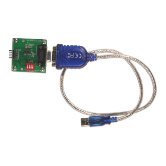
- Page 4 Overview This document is intended to give an idea about in circuit serial programming of the Fujitsu F MC16LX/FR family flash Microcontroller using an adapter cable. This method allows the user to program the microcontroller directly on the target system without additional RS232 circuit. This solution saves some space on the target...
- Page 5 Target Board Fujitsu standard Serial programming utility provides the asynchronous method to program the microcontroller. In order to connect the Microcontroller on board to the utility software, only the serial interface lines SOT (Transmit) and SIN (Receive) are necessary. On the PC side to establish a connection to the Microcontroller the RTS and CTS line should be connected together.
- Page 6 Figure 2: Flash Adapter schematic Diagram 1 SIN 2 NC 100nf 3 MD0 4 GND 100nf 5 MD2 6 SOT 7 Pxx 8 Pyy 9 +Vcc 10 NC 100nf 100nf To Target Board 1 C1+ 3 C1- 4 C2+ 5 C2- 11 T1IN T1OUT 14 10 T2IN...
- Page 7 Procedure for Hardware/Software Setup of Flash Adapter The following steps are required to set up the Hardware and software of the flash programming adapter. 1. Download the FLASH programming utility from the CD. 2. Connect one side of the ribbon cable to Adapter (J1) and other side to the user target board (Note: The user board should have the 10-pin header for the cable).
- Page 8 Requirement on Customer Target Board In order to connect the adapter cable to the target board, it is required to have the 10-pin standard IDC header on the target board with the connection shown below. Figure 3 shows the connections from the microcontroller to header.
- Page 9 Table 1: Pin Description of Header on the Target Board Pin No. Description SIN/SI SOT/SO +Vcc Details Connected to the SIN of the Microcontroller. Refer table-2 shown below. Connected to the MD0 pin of the MCU Ground of the Target board and MCU Connected to the MD2 pin of the MCU...
- Page 10 Appendix A MCU Pins used for Flash asynchronous Programming in F2MC Family...
- Page 11 Microcontroller pins used for Serial Programming...
- Page 12 Microcontroller pins used for Serial Programming...
- Page 13 Appendix B MCU Pins used for Flash asynchronous Programming in FR Family...
- Page 14 Microcontroller pins used for Serial Programming Type MB91F109 MB91F133 MB91F233 MB91F264 MB91FV310/F312 MB91F353/F355 MB91F362/365/366/367/368/369 Serial Data Serial data Input pin output pin SI0/PF0/TRG0 SO0/PF1/TRG1 PI0/SIN1 P11/SOT1 P00/SIN0 PO1/SOT0 P20/SIN0 P21/SOT0 PH3/SI3 PH4/SO3 SIN0 SOT0 Starting pin for programming program P20, P21 P20, P21 P10, P11 P44, P45...
Need help?
Do you have a question about the FMC-16LX/FR and is the answer not in the manual?
Questions and answers