
Related Manuals for Munters MFS36


Summary of Contents for Munters MFS36
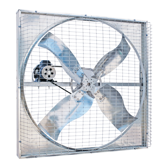
- Page 1 Manual for use and maintenance + CE Declaration of conformity Air circulation fan Models: MFS36 - MFS52 Ag/MIT/UmGB-2085-04/13 rev1.1...
- Page 2 Munters Italy S.p.A. reserves the right to effect modifications to the apparatus in accordance with technical and legal developments.
-
Page 3: Table Of Contents
OPERATING CONDITIONS INSTALLATION 5.1 Assembly of the fan 5.2 Tensioning belt adjuster 5.3 Belt tensioner (optional) 5.4 Tilting device 5.5 Placement of fans 5.6 Electrical wiring COMMISSIONING TECHNICAL DATA 7.1 Dimensions 7.2 Technical specification 7.3 Motor specifications © Munters AB, 2013... - Page 4 Index MAINTENANCE 8.1 Introduction 8.2 Cleaning 8.3 Belt tensioning check up 8.4 Tensioning belt adjuster 8.5 Replacement of V-belt 8.6 Fan bearing lubrication 8.7 Propeller replacement SPARE PART LIST WARRANTY © Munters AB, 2013...
-
Page 5: Ce Declaration
DECLARES ON ITS OWN RESPONSIBILITY THAT THE APPARATUS Circulation fan designed for moving air to control Designation temperature and humidity in livestock. Model MFS36 - MFS52 Year of manufacture 2012 CONFORMS WITH THE ESSENTIAL SAFETY REqUIREMENTS STATED BY APPARATUS DIRECTIVE 2006/42/EC... -
Page 6: Disclaimer
The information contained herein has been prepared by qualified experts within Munters. While we believe the information is accurate and complete, we make no warranty or representation for any particular purposes. The information is offered in good faith and with the understanding that any use of the units or accessories in breach of the directions and warnings in this document is at the sole discretion and risk of the user. -
Page 7: Safety Aspects
Safety aspects 2.1 General The safety of fans is assured by Munters in compliance with the safety requirements indicated by the CE label. Safe functioning is assured only when the installation procedure and the instructions for use have been carefully followed. -
Page 8: Before Using
• wall/column mounting system with tilting mechanism (optional extra); to be used when the fan needs to be mounted next to a wall or column; • tilting mechanism with chain (optional extra); to be used when the fan needs to be suspended from the roof of the structure. © Munters AB, 2013... -
Page 9: Operating Conditions
Normal ambient temperature limits are –25°C to +50°C. Maximum altitude is 1000 m above sea level. Should a fan be required to operate at a higher altitude, the loss in mass flow (heat removing capacity) due to lower air density should be taken into consideration. © Munters AB, 2013... -
Page 10: Installation
See section 8.3 for establishing the correct V-belt tension. 8. Tighten the two bolts in the motor plate so that the V-belt remains in tension. 9. Close the safety meshes, re-insert and tighten the screws. fig.1 © Munters AB, 2013... -
Page 11: Tensioning Belt Adjuster
9. Rotate the propeller by hand so that the V-belt gets completely into the groove on the central pulley. 10. Push the motor away from the centre of the fan to tighten the V-belt. See section 8.3 for establishing the correct V-belt tension. © Munters AB, 2013... - Page 12 11. Be sure to adjust the two M6 nuts and the grub screw, in order to avoid any clearance of it. 12. Tighten the two bolts in the motor plate so that the V-belt remains in tension. 13. Close the safety meshes, re-insert and tighten the screws. fig.2 © Munters AB, 2013...
- Page 13 Chapter5 Installation Holes for pulley fig.3 Motor Frequency Tensioner Hole [Hp] [Hz] n° note: be sure to adjust the grub screw in order to guarantee the correct belt tensioning, by moving the 2 nuts. © Munters AB, 2013...
-
Page 14: Belt Tensioner (Optional)
2 and 3 on the opposite half of the tensioner. Hold tensioner at this setting and tighten the bolt fastening the tensioner to the motor base. Second mark on Mark on base tensioner arm fig.5 © Munters AB, 2013... -
Page 15: Tilting Device
Straight edge fig.6 5.4 Tilting device The fan (MFS36-52) can be tilted both in vertical and horizontal as indicated below: Metal structure If the fan is directly fixed to a metal structure, M8 bolts - 8.8 type, should be used and screwed into the proper threaded inserts placed on the body (2 on each side). - Page 16 HORIZONTAL TILTING 1. Loosen side bolts (it is not necessary to remove the bolts completely from the support). 2. Tilt the fan to the desired angle. 3. Fasten the bolts from the step 1. fig.11 © Munters AB, 2013...
-
Page 17: Placement Of Fans
The fan is delivered without an electrical control box, but the fan motor comes already wired. Connection to the power supply must be done by means of a thermal overload protection switch, whose size depends on motor power. For safety reasons the overload switch can be locked by a padlock, not supplied by Munters. © Munters AB, 2013... - Page 18 3 x 400V 3 x 230V fig.15 1 x 230V fig.16 = Overload protection switch = Circuit breaker = Fan motor © Munters AB, 2013...
- Page 19 Failure to operate the fan with an overload protection device will render the motor guarantee null and void. Such motor overload protection devices can be note ordered from Munters and be supplied with the fans. The connection cable must be completely extracted from the fan housing in order Warning to avoid being damaged by moving parts.
- Page 20 (no. 3 in diagram). To change the direction of rotation of a three-phase motor it is necessary to change the connection of two of the phases. fig.17 © Munters AB, 2013...
-
Page 21: Commissioning
Wait until the electrical power has been Warning switched off and the fan has come to a complete stand still. Lock the electrical switch in the off position with a pad lock while working on the fan. © Munters AB, 2013... -
Page 22: Technical Data
Technical data 7.1 Dimensions MFS36 fig.18 MFS52 fig.19 Fan dimensions [mm] Model MFS36 1,085 1,085 180* MFS52 1,425 1,425 220* 1,330 * Distance may vary according to the type motor installed. © Munters AB, 2013... -
Page 23: Technical Specification
[12.7] [19.7] [14.9] Max. operating temperature °C [°F] 50 [122] Nominal propeller speed [rpm] IEC protective class of electric motor IP55 Electric motor winding insulation grade *excludes safety kit for installation below 2.7m above the floor. © Munters AB, 2013... -
Page 24: Motor Specifications
MFS52 single 200/230 1,350 multi 200/230 1,350 single 208/230 1,660 single 230/400 3.5/2 1,400 single 230/400 3.5/2 1,700 multi 230/400 4.3/2.5 1,380 multi 230/400 3.8/2.2 1,640 1,500 single 230/400 6.1/3.5 1,400 1,500 single 230/400 5.5/3.2 1,680 © Munters AB, 2013... - Page 25 10 mm, when pushed in by thumb. Tighten fan belt after this fan has been running for 3 days. Without adjusting the Warning tension, transmission components can wear out early. © Munters AB, 2013...
- Page 26 In this particular event the manufacturer refuses all responsibility on consequent damages caused to things and people and considers any kind of warranty lost. © Munters AB, 2013...
- Page 27 7. fasten the 25mm hexagonal nut onto the shaft of the propeller assembly; 8. tighten the V-belt by pushing the motor away from the centre of the fan and then tighten the bolts on the motor frame. fig.23 © Munters AB, 2013...
- Page 28 M8 bolts holding the propeller to the fan; 2. remove the propeller; 3. insert the new propeller; 4. tighten the four M8 bolts holding the propeller to the fan and re- install the pyramidal safety mesh. fig.24 © Munters AB, 2013...
-
Page 29: Spare Part List
Spare part list MFS36 fig.25 © Munters AB, 2013... - Page 30 STICKER NO HIGH PRESSURE 42x118 2.23 STICKER 95x115 2.24 WARNING STICKER B-1997 70x105 GROUP 3: PROPELLER PROPELLER INOx/GALV. GROUP 4: PULLEY CENTRAL PULLEY TICK HExAGON NUT M6x6 UNI 5587 GALV. PLAIN WASHER D6,4x12,5 UNI 659 CENTRAL PULLEY DP325x1A © Munters AB, 2013...
- Page 31 PD105 H19 PD130 H19 HP1.0 PD150 H19 PD125 H19 PD150 H19 PD125 H19 PD150 H19 PD125 H19 PD150 H19 BOLTS&NUTS MODELS HP0.5/0.75 - 50/60HZ TICK HExAGON NUT M8x8 UNI 5587 GALV. PLAIN WASHER D8,4x17 UNI 659 © Munters AB, 2013...
- Page 32 HExAGON BOLT M8x25 8,8 UNI 5739 GALV. HExAGON BOLT M6x20 8,8 UNI 5739 GALV. PLAIN WASHER D6,7x24 UNI 659 HOLES FOR MOTOR = HOLES FOR 0.5HP MOTORS = HOLES FOR 0.75HP MOTORS = HOLES FOR 1.0HP MOTORS fig.27 © Munters AB, 2013...
- Page 33 Chapter9 Spare part list MFS52 fig.28 REF. DESCRIPTION qUANTITY GROUP 1: SAFETY MESHES KIT SAFETY MESHES PYRAMIDAL SAFETY MESH 1665x1660 126x66 GALV. © Munters AB, 2013...
- Page 34 TOP/BOTTOM PANEL 1,420x175.5x0.8 GALV. 2.24 VENTURI GALV. 2.25 EUROEMME STICKER 18x131 2.26 EUROEMME STICKER 24,6x180 2.27 STICKER NO HIGH PRESSURE 42x118 2.28 STICKER 95x115 2.29 WARNING STICKER 70x105 GROUP 3: PROPELLER PROPELLER INOx/GALV. GROUP 4: PULLEY CENTRAL PULLEY © Munters AB, 2013...
- Page 35 V-BELT A61-1510 GROUP 6: MOTOR SEE MOTOR TABLE GROUP 7: OPTIONAL KITS CHAIN SUSPENSION KIT WALL/COLUMN MOUNTING SYSTEM TENSIONER PLASTIC ADAPTOR FOR BELT TENSIONER SPRING WASHER D10.5 UNI 8842A HEx BOLT M10x90x26N ISO 4014 MOTOR fig.29 © Munters AB, 2013...
- Page 36 HExAGON BOLT M8x25 8,8 UNI 5739. HExAGON BOLT M8x20 8,8 UNI 5739 SPRING WASHER D8,4x14,4 UNI 1751 PLAIN WASHER D8x32 DIN 126 HOLES FOR MOTOR = HOLES FOR 1.0HP MOTORS = HOLES FOR 2.0HP MOTORS fig.30 © Munters AB, 2013...
- Page 37 Munters plant was required: if this is not done, the user is fully responsible for the damage which they could suffer.
- Page 38 Requests for technical assistance and spare parts must be made directly to the manufacturer, at the following address: Munters Italy S.p.A Strada Piani, 2 18027 Chiusavecchia (IM), Italy Tel: +39 0183 52 11 Fax: +39 0183 521 333 © Munters AB, 2013...
- Page 39 Munters Brasil Industria e Comercio Ltda, Phone +55 41 3317 5050, Canada Munters Corporation Mason, Phone +1 517 676 7070, China Munters Air Treatment Equipment (Beijing) Co. Ltd, Phone +86 10 80 481 121, Denmark Munters A/S, Phone +45 9862 3311, India...
Need help?
Do you have a question about the MFS36 and is the answer not in the manual?
Questions and answers