Table of Contents
Advertisement
HPE Smart Array P824i-p MR Gen10
User Guide
Abstract
This document includes feature, installation, and configuration information about Hewlett
Packard Enterprise Smart Array P824i-p MR Gen10 controller and is for the person who
installs, administers, and troubleshoots servers and storage systems. Hewlett Packard
Enterprise assumes you are qualified in the servicing of computer equipment and trained in
recognizing hazards in products with hazardous energy levels.
Part Number: P06372-002
Published: March 2019
Edition: 2
Advertisement
Table of Contents

Subscribe to Our Youtube Channel
Related Manuals for HPE Smart Array P824i-p MR Gen10


Summary of Contents for HPE Smart Array P824i-p MR Gen10
- Page 1 Abstract This document includes feature, installation, and configuration information about Hewlett Packard Enterprise Smart Array P824i-p MR Gen10 controller and is for the person who installs, administers, and troubleshoots servers and storage systems. Hewlett Packard Enterprise assumes you are qualified in the servicing of computer equipment and trained in recognizing hazards in products with hazardous energy levels.
- Page 2 © Copyright 2018, 2019 Hewlett Packard Enterprise Development LP Notices The information contained herein is subject to change without notice. The only warranties for Hewlett Packard Enterprise products and services are set forth in the express warranty statements accompanying such products and services. Nothing herein should be construed as constituting an additional warranty. Hewlett Packard Enterprise shall not be liable for technical or editorial errors or omissions contained herein.
-
Page 3: Table Of Contents
Cache Error Checking and Correction (ECC)..............25 Thermal monitoring......................25 Performance..........................25 SAS storage link speed....................25 HPE Smart Array MR FastPath..................25 HPE Smart Array MR CacheCade................... 26 Cache..........................26 Installation..................... 29 Installation...........................29 Installing an HPE Smart Array P824i-p MR Gen10 controller in a configured server..29... - Page 4 Installing an HPE Smart Array P824i-p MR Gen10 controller in an unconfigured server..........................30 Configuring boot controller options.................. 31 Connecting storage devices.....................33 Cable part numbers......................33 Configuration..................34 Array and controller configuration....................34 HPE MR Storage Administrator..................34 StorCLI..........................35 UEFI System Utilities......................35 Smart Array MR Gen10 configuration in UEFI System Utilities..........
-
Page 5: Hpe Smart Array P824I-P Mr Gen10
UEFI Storage Configuration Utility HPE Smart Array P824i-p MR Gen10 is supported in HPE ProLiant Gen10 servers. The HPE Smart Array controllers are named according to the features of the controller, as shown below. HPE Smart Array P824i-p MR Gen10... -
Page 6: Features
This section lists the features supported by the P824i-p Smart Array MR controller. For additional information about the features, see MR Storage Administrator User Guide at the Hewlett Packard Enterprise website http://www.hpe.com/support/MRSA. Operating environments The following operating environments are supported: •... -
Page 7: Transformation
Extend logical drive • Migrate RAID level • Transformation priority Drive technology The following drive technology features are supported: • HPE SmartDrive LED • Consistency check • Discarding pinned cache • Online drive firmware update Security The following security features are supported: •... -
Page 8: Raid Technologies
• Drive caching • Stripe size selection RAID technologies Selecting the right RAID type for your IT infrastructure The RAID setting that you select is based upon the following: • The number of parity groups that you have • The fault tolerance required •... - Page 9 Configuring the RAID write performance If your environment requires high write performance, select a RAID type that is optimized for write performance The chart below shows how RAID 10, 5, 50, 6, and 60 compare to the percent write performance of RAID The data in the chart assumes that drives are limited and that drive write performance is the same as drive read performance.
- Page 10 RAID type Disk I/O for every host write RAID 5 RAID 6 Configuring the RAID usable capacity If your environment requires a high usable capacity, select a RAID type that is optimized for usable capacity. The chart in this section demonstrates the relationship between the number of drives in the array and the percent usable capacity over the capacity for RAID 0.
- Page 11 Configuring the storage solution The chart in this section shows the relevance of the RAID type to the requirements of your environment. Depending on your requirements, you should optimize the RAID types as follows: • RAID 6/60: Optimize for fault tolerance and usable capacity. •...
-
Page 12: Mixed Mode (Raid And Jbod Simultaneously)
Mixed mode (RAID and JBOD simultaneously) Mixed mode allows for any drive to be a member of a logical drive (logical volume or RAID volume), unconfigured and hidden from the operating system, or in a JBOD drive state which exposes the drive to the host operating system as a physical drive. -
Page 13: Mirroring
This method has the following benefits: • Useful when performance and low cost are more important than data protection. • Has the highest write performance of all RAID methods. • Has the lowest cost per unit of stored data of all RAID methods. •... - Page 14 When the array has more than two physical drives, drives are mirrored in pairs, and the fault-tolerance method is known as RAID 1+0 or RAID 10. If a physical drive fails, the remaining drive in the mirrored pair can still provide all the necessary data. Several drives in the array can fail without incurring data loss, as long as no two failed drives belong to the same mirrored pair.
-
Page 15: Parity
Read load balancing In each mirrored pair or trio, Smart Array balances read requests between drives based upon individual drive load. This method has the benefit of enabling higher read performance and lower read latency. Parity RAID 5 RAID 5 protects data using parity (denoted by Px,y in the figure). Parity data is calculated by summing (XOR) the data from each drive within the stripe. - Page 16 For any given number of drives, data loss is least likely to occur when the drives are arranged into the configuration that has the largest possible number of parity groups. For example, four parity groups of three drives are more secure than three parity groups of four drives. However, less data can be stored on the array with the larger number of parity groups.
- Page 17 This method is most useful when data loss is unacceptable but cost is also an important factor. The probability that data loss will occur when an array is configured with RAID 6 (Advanced Data Guarding (ADG)) is less than it would be if it were configured with RAID 5. This method has the following benefits: •...
- Page 18 • Higher performance than for RAID 6, especially during writes. • Better fault tolerance than RAID 0, 5, 50, or 6. • Up to 2n physical drives can fail (where n is the number of parity groups) without loss of data, as long as no more than two failed drives are in the same parity group.
-
Page 19: Spare Drives
Full initialization During full initialization, a complete initialization is done on the new configuration. You cannot write data to the new logical drive until the initialization is complete. This process can take a long time if the drives are large. This initialization overwrites all blocks and destroys all data on the logical drive. Monitor the progress of the initialization process using the progress indicator. -
Page 20: Drive Rebuild
It must have a capacity no less than the capacity of the smallest drive in the array. This operation uses the Modify Array option in the HPE MR Storage Administrator user interface. This feature is supported when there is a single logical drive configured in the array. -
Page 21: Drive Technology
Increase the capacity of an existing logical drive by specifying a new size. Once the task is performed, use operating system partitioning software to take advantage of the extended space available. Enable this feature in the HPE MR Storage Administrator user interface using the Expand option within the Logical Drive Actions menu. - Page 22 Item Status Definition Locate Solid blue The drive is being identified by a host application. Flashing blue The drive carrier firmware is being updated or requires an update. Activity ring Rotating green Drive activity No drive activity Do not remove Solid white Do not remove the drive.
-
Page 23: Consistency Check
Instead of taking the hard disk drive (HDD) offline before loading a new firmware image, you can download an updated HDD firmware image to the HPE Smart Array controller and update all of the HDDs the next time you reboot the server. -
Page 24: Security
Security Drive erase Erase data on drives by using the Drive Erase option. The erase operation consists of a series of write operations to a drive that overwrite every user-accessible sector of the drive with specified patterns. The erase operation can be repeated in multiple passes using different data patterns for enhanced security. The erase operation is performed as a background task. -
Page 25: Reliability
Reliability Recovery ROM HPE Smart Array controllers store a redundant copy of the controller firmware image to protect against data corruption. If the active firmware image becomes corrupt, HPE Smart Array controllers use the redundant firmware image and continue operating. The recovery ROM provides protection against power outages during firmware flashing. -
Page 26: Hpe Smart Array Mr Cachecade
Write IOs to RAID 1, 5, and 6 are not allowed through FastPath. HPE Smart Array MR CacheCade The CacheCade read and write feature eliminates the need for manually configured hybrid arrays by intelligently and dynamically managing frequently accessed data and copying it from HDD volumes to a higher performance layer of SSD cache. - Page 27 64 KiB to 1 MiB). These strips are distributed across the physical drives in the array. A "stripe" is one set of strips. Striping helps to distribute the I/O workload across multiple physical drives. HPE Smart Array controllers configure strips, not stripes.
- Page 28 The best performance and drive longevity is obtained by aligning and sizing the strip and thus stripe size to the application I/O request size and alignment. The smaller (<= 64 KiB) the strip size, the longer the background parity scans and rebuilds take and the more impact to the host I/O during these operations. However, multiple stripes can be checked or rebuilt concurrently.
-
Page 29: Installation
Installation Use the topics in this section to install the controller into a server that is already configured or a server that is not yet configured. Installing an HPE Smart Array P824i-p MR Gen10 controller in a configured server Procedure Back up data on the system. -
Page 30: Installing An Hpe Smart Array P824I-P Mr Gen10 Controller In An Unconfigured Server
16. Connect the controller backup power cable. 17. Connect storage devices to the controller. For cabling information, see the server user guide. 18. Install the HPE Smart Storage Battery or HPE Smart Storage Hybrid Capacitor. 19. Reinstall the riser. 20. Connect peripheral devices to the server. -
Page 31: Configuring Boot Controller Options
Installing the operating system with the HPE Smart Array MR Gen10 P824i-p controller driver Prerequisites Ensure that you have the HPE Smart Array MR Gen10 P824i-p controller driver available. Obtain it by extracting it from the SPP (http://www.hpe.com/servers/spp) or by downloading it from the Hewlett Packard Enterprise Support website https://www.support.hpe.com. - Page 32 Selecting a boot mode Procedure 1. From the System Utilities screen, select System Configuration > Boot Options > Boot Mode, and press the Enter key. 2. Select a setting and press the Enter key. • UEFI Mode (default) - Configures the system to boot to a UEFI-compatible operating system. NOTE: When booting to the UEFI Mode, configure the system to use native UEFI graphic drivers.
-
Page 33: Connecting Storage Devices
Connecting storage devices For more information about supported drive models on specific Gen10 HPE servers, see the QuickSpecs for the specific server. Connecting internal storage Procedure 1. Power down the server. 2. Install drives, if necessary. Hewlett Packard Enterprise recommends drives of similar type. All drives grouped in a logical drive must meet the following criteria: •... -
Page 34: Configuration
NOTE: • Any RAID configuration created for the HPE Smart Array MR controller is not available to HPE Smart Array SR controllers. • The message "Data Protection disabled" in the logical drive properties can be ignored as it refers to a feature not currently supported by the HPE MR Storage Administrator product. -
Page 35: Storcli
The Storage Command Line Interface (StorCLI) tool is the command line management software designed for the HPE Smart Array MR controller. StorCLI is a command line interface that is designed to be easy to use, consistent, and easy to script. -
Page 36: Smart Array Mr Gen10 Configuration In Uefi System Utilities
Use the Dashboard View screen to view the properties of the controller, view the server profile, and perform common actions. Procedure 1. From the System Utilities screen, select System Configuration > HPE Smart Array P824i-p MR Gen10. 2. In the Dashboard View panel, click Main Menu to access the Main Menu. -
Page 37: Configuration Management
Unconfigured Good drives for use in your logical drive. Procedure 1. From the System Utilities screen, select System Configuration > HPE Smart Array P824i-p MR Gen10 > Main Menu > Configuration Management > Create Logical Drive. - Page 38 Option Description Select Drives From Enables the physical drive selection option: • Free Capacity uses unused (free) drive capacity that is already part of a logical drive. • Unconfigured Capacity creates a logical drive on unconfigured drives. Select Drive View steps here. Logical Drive Name Name of logical drive Logical Drive Size...
- Page 39 Option Description Disable background Background initialization status: initialization • No - (default) leaves the background initialization enabled. This means that a new configuration can be initialized in the background while you use the app to do other configuration tasks. • Yes - disables background initialization for configurations on this controller.
- Page 40 WARNING: Creating a logical drive will permanently delete any data on an associated drive. Procedure 1. From the System Utilities screen, select System Configuration > HPE Smart Array P824i-p MR Gen10 > Main Menu > Configuration Management > Create Profile Based Logical Drive.
- Page 41 WARNING: Creating a logical drive will permanently delete any data on an associated drive. Procedure 1. From the System Utilities screen, select System Configuration > HPE Smart Array P824i-p MR Gen10 > Main Menu > Configuration Management > Create CacheCade Logical Drive.
- Page 42 The Success screen appears to confirm that the operation completed successfully. For the drive status change to reflect on the Drive Management screen, refresh the view. a. Select System Configuration > HPE Smart Array P824i-p MR Gen10 > Main Menu > Drive Management .
-
Page 43: Controller Management
WARNING: Clearing a configuration deletes all of the logical drives and spare drives attached to the controller. Procedure 1. From the System Utilities screen, select System Configuration > HPE Smart Array P824i-p MR Gen10 > Main Menu > Configuration Management > Clear Configuration. 2. In the Warning message screen, click Confirm and Yes to proceed. - Page 44 Advanced controller management Clearing controller events Procedure 1. From the System Utilities screen, select System Configuration > HPE Smart Array P824i-p MR Gen10 > Main Menu > Controller Management. 2. In the Controller Management screen, select Advanced Controller Management. 3. In the Advanced Controller Management screen, select Clear Controller Events.
- Page 45 The Success screen appears to state that the operation is performed successfully. Managing link speed Procedure 1. From the System Utilities screen, select System Configuration > HPE Smart Array P824i-p MR Gen10 > Main Menu > Controller Management. 2. In the Controller Management screen, select Advanced Controller Management.
- Page 46 The Success screen appears to confirm that the operation is performed successfully. Setting factory defaults Procedure 1. From the System Utilities screen, select System Configuration > HPE Smart Array P824i-p MR Gen10 > Main Menu > Controller Management. 2. In the Controller Management screen, select Advanced Controller Management.
- Page 47 Coercion Mode Drive coercion forces the drives of varying capacities to the same size so they can be used in an array. The coercion mode options are None, 128 MB, and 1 GB. Boot Mode Specifies options to handle errors (if they occur) during boot time.
- Page 48 8. Click Apply Changes. Configuring cache and memory settings Procedure 1. From the System Utilities screen, select System Configuration > HPE Smart Array P824i-p MR Gen10 > Main Menu > Controller Management. 2. In the Controller Management screen, select Advanced Controller Properties .
- Page 49 Configuring Spare settings Procedure 1. From the System Utilities screen, select System Configuration > HPE Smart Array P824i-p MR Gen10 > Main Menu > Controller Management. 2. In the Controller Management screen, select Advanced Controller Properties . 3. In the Advanced Controller Properties screen, click Spare to configure the Spare settings.
-
Page 50: Logical Drive Management
Viewing and configuring properties of a logical drive Procedure 1. From the System Utilities screen, select System Configuration > HPE Smart Array P824i-p MR Gen10 > Main Menu > Logical Drive Management. 2. In the Logical Drive Management screen, select the logical drive. - Page 51 Force. Deleting a logical drive Procedure 1. From the System Utilities screen, select System Configuration > HPE Smart Array P824i-p MR Gen10 > Main Menu > Logical Drive Management. 2. In the Logical Drive Management screen, select the logical drive.
-
Page 52: Drive Management
Locating a physical drive associated with a logical drive Procedure 1. From the System Utilities screen, select System Configuration > HPE Smart Array P824i-p MR Gen10 > Main Menu > Logical Drive Management. 2. In the Logical Drive Management screen, select the logical drive. - Page 53 Property Description Drive ID ID of the drive Status Current drive status Size Size of the drive in MB/GB/TB Type Device type Model Model number of the drive Hardware Vendor Hardware manufacturer Associated Logical Drive List of logical drives associated with the drive 4.
- Page 54 Locating a drive Procedure 1. From the System Utilities screen, select System Configuration > HPE Smart Array P824i-p MR Gen10 > Main Menu > Drive Management. 2. In the Drive Management screen, select the drive that you want to locate.
- Page 55 The Success screen appears to confirm that the operation completed successfully. For the drive status change to reflect on the Drive Management screen, refresh the view. a. Select System Configuration > HPE Smart Array P824i-p MR Gen10 > Main Menu > Drive Management .
- Page 56 Making an Unconfigured Good drive Procedure 1. From the System Utilities screen, select System Configuration > HPE Smart Array P824i-p MR Gen10 > Main Menu > Drive Management . 2. In the Drive Management screen, select the JBOD drive that you want to convert to Unconfigured Good.
- Page 57 Unassigning a global spare drive Procedure 1. From the System Utilities screen, select System Configuration > HPE Smart Array P824i-p MR Gen10 > Main Menu > Drive Management . 2. In the Drive Management screen, select the spare drive that you want to unassign.
-
Page 58: Maintenance
• Error Message Guide for HPE ProLiant Gen10 servers and HPE Synergy provides a list of error messages and information to assist with interpreting and resolving error messages. •... -
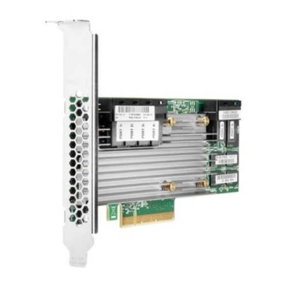
Page 59: Models
Models HPE Smart Array P824i-p MR Gen10 Controller Components Item Description Internal SAS port 1i Internal SAS port 2i Internal SAS port 3i Internal SAS port 4i Controller backup power cable connector Internal SAS port 5i Internal SAS port 6i... -
Page 60: Energy Pack Options
One energy pack option can support multiple devices. An energy pack option is required for P-class Smart Array controllers. Once installed, the status of the energy pack displays in HPE iLO. For more information, see the HPE iLO user guide on the Hewlett Packard Enterprise website (http:// www.hpe.com/support/ilo-docs). -
Page 61: Energy Pack Specifications
Energy pack specifications Table 1: HPE Smart Storage Battery (96W) Feature Description Time required to recharge Smart Storage Battery 96 W: 2 hours (For maximum load of 24 devices) Duration of Smart Storage Battery backup 150 seconds (maximum support) The Smart Storage Battery provides a sufficient... -
Page 62: Specifications
Specifications Memory and storage capacity conventions Memory capacities are specified using binary prefixes: • KiB = 2 bytes • MiB = 2 bytes • GiB = 2 bytes • TiB = 2 bytes Storage capacities are specified using SI prefixes: •... -
Page 63: Support And Other Resources
Support and other resources Accessing Hewlett Packard Enterprise Support • For live assistance, go to the Contact Hewlett Packard Enterprise Worldwide website: http://www.hpe.com/info/assistance • To access documentation and support services, go to the Hewlett Packard Enterprise Support Center website: http://www.hpe.com/support/hpesc Information to collect •... -
Page 64: Customer Self Repair
IMPORTANT: Access to some updates might require product entitlement when accessed through the Hewlett Packard Enterprise Support Center. You must have an HPE Passport set up with relevant entitlements. Customer self repair Hewlett Packard Enterprise customer self repair (CSR) programs allow you to repair your product. If a CSR part needs to be replaced, it will be shipped directly to you so that you can install it at your convenience. -
Page 65: Regulatory Information
Documentation Feedback (docsfeedback@hpe.com). When submitting your feedback, include the document title, part number, edition, and publication date located on the front cover of the document. For online help content, include the product name, product version, help edition, and publication date located on the legal notices page. -
Page 66: Websites
Websites General websites Hewlett Packard Enterprise Information Library www.hpe.com/info/EIL Subscription Service/Support Alerts www.hpe.com/support/e-updates Insight Remote Support www.hpe.com/info/insightremotesupport/docs For additional general support websites, see Support and other resources. Product websites HPE Smart Array http://www.hpe.com/info/P824i-pdocs HPE Integrated Lights-Out www.hpe.com/info/ilo Websites...
Need help?
Do you have a question about the Smart Array P824i-p MR Gen10 and is the answer not in the manual?
Questions and answers