
Subscribe to Our Youtube Channel
Related Manuals for Woodward MRIK3-C


Summary of Contents for Woodward MRIK3-C
- Page 1 MRIK3-C Digital time overcurrent relay with Control function and auto reclosing Manual MRIK3-C (RevisionA)
- Page 2 Woodward Manual MRIK3-C EN Woodward Governor Company reserves the right to update any portion of this publication at any time. Information provided by Woodward Governor Company is believed to be correct and reliable. However, no responsibility is as- sumed by Woodward Governor Company unless otherwise expressly undertaken.
-
Page 3: Table Of Contents
Supervision of the circuit breaker ready information ............. 23 5.4.9 External blocking ......................23 5.4.10 Time sequence diagrams of MRIK3-C ..............23 5.4.11 The unit is programmed for two shots, successful AR at the second shot ....23 5.4.12 The unit is programmed for two shots, unsuccessful AR .......... - Page 4 Woodward Manual MRIK3-C EN 5.7.1 Introduction ........................29 5.7.2 Interlocking / Password for control mode ..............29 5.7.3 Operating assignment of C.B. control ................29 5.7.4 Changing the operating assignment ................29 ...
- Page 5 Secondary injection test ....................65 7.3.1 Test equipment......................65 Example of test circuit for MRIK3-C relays without directional feature ......66 7.4.1 Checking the input circuits and measured values ............66 7.4.2 Checking the operating and resetting values of the relay ..........
- Page 6 Woodward Manual MRIK3-C EN Order form ....................82 DOK-TD-MRIK3-C Rev. A...
-
Page 7: Comments On The Manual
(projecting) work, parameter setting or adjustment changes done by the customer. The warranty expires after a device has been opened by others than Woodward Kempen special- ists. Warranty and liability conditions stated in Woodward Kempen GmbH General Terms and Condi- tions are not supplemented by the above mentioned explanations. -
Page 8: Important Definitions
How to use this instruction In this instruction the technical description of all MRIK3-C versions is included. The user is given a comprehensive insight into the various applications, the selection, installation, setting of parame- ters and putting into operation of the MRIK3-C. -
Page 9: Electrostatic Discharge Awareness
Guide for Handling and Protection of Electronic Controls, Printed Circuit Boards, and Modules. Woodward Kempen GmbH reserves the right to update any portion of this publication at any time. Information provided by Woodward Kempen GmbH is believed to be correct and relia- ble. -
Page 10: Introduction And Application
Manual MRIK3-C EN 2. Introduction and Application The digital net protection relay MRIK3-C an universal time - over -current and earth fault relay with integrated control- and supervision function as well as optional an integrated auto reclosing func- tion The earth fault protection is applicable for insulated and compensated grids. The controlling of... -
Page 11: Design
Manual MRIK3-C EN Woodward 4. Design Connections Figure 4.1: Connection diagram MRIK3-ICE Figure 4.2: Connection diagram MRIK3-ICER/ICXR DOK-TD-MRIK3-C Rev. A... - Page 12 Woodward Manual MRIK3-C EN L1.1 L1.2 L2.1 L2.2 L3.1 L3.2 Figure 4.3: Measuring of phase currents and earth current detection in Holmgreen connection (IE) This kind of connection can be used where three phase CTs are available and a combination of phase and earth current measuring is required.
-
Page 13: Analog Input Circuits
4.1.2 Output relays The MRIK3-C has 5 output relays. Two of these relays with two change-over contacts and three re- lays with one change-over contact each are used for signalling. The protective functions can be freely allocated except of those for the self-supervision relay. -
Page 14: Low/High Range Of The Digital Inputs
Woodward Manual MRIK3-C EN 4.1.4 Low/High range of the digital Inputs The MRI(K)3-C is equipped with a wide-range power supply unit and hence the supply voltage is freely selectable. The switching threshold of the digital inputs, however, has to be fixed in compli- ance with the supply voltage. -
Page 15: Password
Manual MRIK3-C EN Woodward Password 4.2.1 Code jumpers Behind the front plate of the MR-relays there are three code jumpers to preset the following func- tions: Password programming Output relay functions The following figure shows the position and designation of the code jumpers: 4.2.2... -
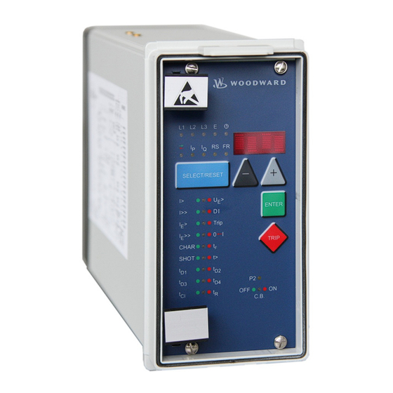
Page 16: Front Plate (For -Ice Relay Type)
Woodward Manual MRIK3-C EN Front plate (for –ICE relay type) The LEDs No, RS and on the MRIK3-C emit a yellow light, all other LEDs are bi-coloured. The LEDs at the left next to the alphanumerical display give a green light during measuring and a red one when a fault sig- nal occurs. -
Page 17: Front Plates (For -Er/-Xr-Relay Types)
Manual MRIK3-C EN Woodward Front plates (for -ER/-XR-relay types) The LEDs I , RS and FR on the MRIK3-ICE and MRI3-ICE emit a yellow light, all other LEDs are bi- coloured. The LEDs at the left next to the alphanumeri- cal display give a green light during measuring and a red one when a fault signal occurs. -
Page 18: Working Principle
Digital circuits The essential part of the MRIK3-C relay is a powerful microcontroller. All of the operations, from the analogue digital conversion to the relay trip decision, are carried out by the microcontroller digitally. The relay program is located in an EPROM (Electrically-Programmable-Read-Only-Memory). With this program the CPU of the microcontroller calculates the three phase currents and ground current in order to detect a possible fault situation in the protected object. -
Page 19: Ar-Ready
Manual MRIK3-C EN Woodward 5.3.3 „AR-ready“ The relay MRIK3-C is in position "AR-ready" status when the following conditions are fulfilled: The circuit breaker is in position "ON",LED CB emit red light the reclaim time has expired, the unit is not in "blocked" status, ... -
Page 20: Description Of The Status Transition
Table 5.1: AR-status transition matrix From Table 5.1 you can detect what status transitions of MRIK3-C are possible. When the unit is for instance in "cycle" status (see also para. 4.3) only two status transitions are possible: ... -
Page 21: Functional Sequence
150 s for the synchronisation signal after the dead times have expired. If the input has not been set after this period has expired, the MRIK3-C stops the AR cycle. The display shows "S/E?". If the digital input is activated during this period, the ON signal is set without delay. -
Page 22: Unsuccessful Reclosing
(C.B. must be tripped within this time). The "start conditions not fulfilled" is evaluated and the MRIK3-C is locked for the duration of the re- claim time when there is a time difference between mains protection-energized and tripping, which is larger than the set "fault time". -
Page 23: Supervision Of The Circuit Breaker Ready Information
After expiration of the dead time t unit MRIK3-C gives the reclosing command to the circuit breaker. If the fault still exists the protec- tion relay trips again and the above mentioned procedure is repeated as long until either the fault was removed (here after the second reclosing) or the number of the set SHOTs is reached. -
Page 24: The Unit Is Programmed For Two Shots, Unsuccessful Ar
Figure 5.3: Manual closing of the C.B. to faulty lines Unit MRIK3-C is in "inactive" status when the circuit breaker is switched off. When the C.B. is manually closed the reclaim time is started. In case there is a faulty line the C.B. is switched off by mains protection of the relay. -
Page 25: Unsuccessful Ar
Manual MRIK3-C EN Woodward 5.4.14 Unsuccessful AR Figure 5.4: Unsuccessful AR The sequence diagram illustrates the various possibilities of an unsuccessful AR. DOK-TD-MRIK3-C Rev. A... -
Page 26: Earth Fault Protection
5.5.1 Generator stator earth fault protection With the generator neutral point earthed as shown in Figure 5.5 the MRIK3-C picks up only to phase earth faults between the generator and the location of the current transformers supplying the relay. Earth faults beyond the current transformers, i.e. on the consumer or line side, will not be detected. -
Page 27: Earth-Fault Directional Feature (Er/Xr-Relay Type)
Total current can be measured by connecting the unit either to a ring core C.T. or to current trans- formers in a Holmgreen circuit. However, maximum sensitivity is achieved if the MRIK3-C protec- tive device is connected to a ring core C. T. See Figure 4.4. - Page 28 Woodward Manual MRIK3-C EN 1. Mains with isolated star point (setting: "earthing: SIN“, "MTA (fixed): -90°) Figure 5.7: Phase position between the residual voltage and zero sequence current for faulted and non-faulted lines in case of isolated systems (sin...
-
Page 29: Control Functions
CB position as well as the CB ready message are supervise by digital inputs.. The status of the CB and the position are indicated by on LED on the front plate of the relay MRIK3-C. The local opera- tion takes place by means of the push buttons on the front plate. Furthermore the position of the CB are signalize to a SCADA system via the serial interface and Modbus RTU protocol. -
Page 30: Saving The Operating Assignment
Woodward Manual MRIK3-C EN 5.7.5 Saving the operating assignment If the changed function is to be saved, the <ENTER> key must be operated. The display shows “SAV?”. If the <ENTER> key is pressed again, you are asked for the password. The display shows ”PSW?”. -
Page 31: Handling Of The Control Function
Woodward 5.7.8 Handling of the control function The control function of the MRIK3-C are activated by push buttons from the front plate of the relay. In the following flow charts the detail handling is shown. Control modus activation Display: MRIK <... - Page 32 Woodward Manual MRIK3-C EN Local operation of the CB. Indication CB position! Detection of CB position CB position evaluation Indication: CB?? Digital input function have to CB Error be set correctly or the auxiliary switches have to connect to the DI's.
-
Page 33: Display For The Control Functions
Manual MRIK3-C EN Woodward 5.7.9 Display for the control functions The logical independence of the control functions and the digital input functions are shown in the following tables depending of the relay status. Indication from display and LED in the control mode... -
Page 34: Led-Indication Under Normal Mode
Woodward Manual MRIK3-C EN 5.7.10 LED-indication under normal mode The logical independence of the control functions and the digital input functions are shown in the following tables depending of the relay status. Indication of display and LED in normal mode. -
Page 35: Led-Indication Auto Reclosing Conditions (Ar)
Manual MRIK3-C EN Woodward 5.7.11 LED-indication auto reclosing conditions (AR) CB position Before switch ON After switch OFF (after 300ms) CB Ready LED CB CB ON CB OFF LED CB Flashed red Flashed red Emits green Emits red Flashed red... -
Page 36: Requirement On The Main Current Transformers
For the nominal range or the lower load range it has to be taken into account that not only the basic accuracy of the MRIK3-C has to be considered but also the transformer accuracy. This applies es- pecially for cases where the Holmgreen circuit is used and for low earth fault currents in isolated networks. -
Page 37: Operation And Adjustments
Manual MRIK3-C EN Woodward Operation and Adjustments Displayed text for parameter settings Function Displayed Text Related LED References Normal operation MRIK Exceeding the measuring max. range Sec. transf. currents indication L1, L2, L3, Chap. 6.4.1 Chap. 6.4.2 Rated frequency f = 50 / f = 60 Chap. -
Page 38: Setting Procedure
Woodward Manual MRIK3-C EN Function Displayed Text Related LED References Save parameter? FLT1, FLT2..Trip = type depend- Chap. 6.13.4 Erase fault memory! Wait Chap. 6.14.1 Software version TRIP Trip = type depend- Manual trip MRIK Chap. 6.14 Inquire password... -
Page 39: Parameter Levels
Manual MRIK3-C EN Woodward Parameter levels The different levels are entered by press the following key or combination of keys. Figure 6.1: Parameter levels For all levels password 1 is valid. DOK-TD-MRIK3-C Rev. A... -
Page 40: System Parameters
Woodward Manual MRIK3-C EN System parameters 6.4.1 Presentation of Measuring Values as Primary Quantities on the Display (Iprim Phase) This parameter makes it possible to present the indications of phase current and earth-fault current separately, i.e. as primary or secondary measuring value. Currents in the kiloampere range are in- dicated with the symbol of unit of measurement k (kilo) as three-digit point. -
Page 41: I2*T Operation Cycle Counter
I2*t Operation cycle counter The relay MRIK3-C provide a measurement unit to determinate the switch off power of the circuit breaker. They start from the point of set the trip output signal and end until the point of the phase current is lower than <2% of the nominal current. -
Page 42: Protection Parameters
In order to avoid an unsuitable combination between trip characteristics and tripping time or time factor, the following measures are initiated by the MRIK3-C: The LED for adjustment of the tripping time or time factor starts to flash after the trip characteristics have changed. -
Page 43: Fast/Time Tripping By Switch On Of The Cb For The Overcurrent Element
Manual MRIK3-C EN Woodward 6.5.4 Fast/Time tripping by switch ON of the CB for the overcurrent element After switch ON the CB a pick up of the I> element happens directly within 200ms, it is possible to switch OFF without time delay when this parameter is already set. -
Page 44: Fast/Time Tripping By Switch On Of The Cb For The Short Circuit Element
Woodward Manual MRIK3-C EN 6.5.9 Fast/Time tripping by switch ON of the CB for the short circuit element After switch ON the CB a pick up of the I>> element happens directly within 200 ms, it is possible to switch OFF without time delay when this parameter is already set. (see chapter 6.5.4) 6.5.10... -
Page 45: Reset Mode For Inverse Time Tripping In Earth Current Path
Reclosing is permitted during this time. It starts with the energizing of the corresponding protection devices. A reclosing attempt follows only if the command time of the protection devices is shorter than the fault time set at MRIK3-C. 6.6.3 Dead time (tD) Starts with the OFF-signal of the circuit breaker. -
Page 46: Close Impulse Time (Tci)
This is the time during which - after switching on (also manually) or after AR - a subsequent reclos- ing is prevented. If the number of the set shots is reached, the MRIK3-C is blocked for this time af- ter the last reclosing attempt. -
Page 47: Control Functions
Manual MRIK3-C EN Woodward Control functions 6.7.1 Block/Trip-time The block/trip serves for recognising a CB failure protection by rear interlocking. Setting of the blocking input will activate the blocking function and block the configured protection functions. (re- fer to chapter 5.11.1) If the block/trip time is not set to EXIT but to an adjustable time (0.1 – 2.00s), the blocking function is cancelled again after this time has expired. -
Page 48: Cb Failure Protection
Woodward Manual MRIK3-C EN 6.7.4 CB failure protection The CB failure protection is based on supervision of phase currents during tripping events. Only af- ter tripping this protective function becomes active. The test criterion is whether all phase currents are dropped to <1% x I... -
Page 49: Interface Parameters
“no“ = no check of the parity Using communication port RS232 or RS485 The MRIK3-C relay provides two possibilities of data exchange communication. The function is described in the manual MR – digital multifunction relays. See chapter 6 Device communication. -
Page 50: Fault Recorder (Fr)
Woodward Manual MRIK3-C EN 6.10 Fault Recorder (FR) 6.10.1 Fault Recorder The existing store can be utilised in two ways: Not to be overwritten Previous recordings will not be overwritten. When there is no memory space left, further recordings are not possible. -
Page 51: Number Of Fault Recordings
Manual MRIK3-C EN Woodward trigger occurence recording duration Tpre Figure 6.7: General Set-Up of the Fault Recorder Each of the storage segments have a fixed storage time where the time before the trigger event can be defined. Via the RS485 interface the data can be read out by means of a PC provided with HTL/PL-Soft4. -
Page 52: Setting Of The Clock
Blocking the protection functions Blocking of the protective functions: The MRIK3-C is equipped with a blocking function that can be parameterized arbitrary. Connecting supply voltage to terminals at a assigned digital blocking of those functions which were selected by the user takes place. -
Page 53: Assignment Of The Output Relays
The relays are assigned as follows: LEDs I>, I>>, I >, I when the output relays are assigned as alarm relays and red as tripping relays. In case of the MRIK3-C models the LEDs I>; I>>; I > and I >> always light up in conjunction with t>. - Page 54 Note: Coding plugs J3, described in the general description „MR- Digital Multifunctional Relay“ have only one function in the MRIK3-C. At the end of this description an Adjustment List can be found in which the customer-specific adjustments can be filled-in.
- Page 55 Manual MRIK3-C EN Woodward Display- Corresponding Relay function Output relay Symbol Function indication LEDs I> Alarm _ 2 _ _ I> tI> Tripping 1 _ _ _ I>+t>, I>> Alarm _ 2 _ _ I>> tI>> Tripping 1 _ _ _ I>>+t>,...
-
Page 56: Assignment Of The Ar Functions
Woodward Manual MRIK3-C EN 6.12.3 Assignment of the AR functions The last activation of the <SELECT/RESET> key in the relay assignment mode will activate the AR assignment mode. The accompanied LEDs indicate which functions will be assigned to the individual protec- tion stages for parameter setting before the 1 ... - Page 57 Manual MRIK3-C EN Woodward Function Protection step Display-indication corresponding LED Trip cause I> TIME (FAST, BLOC) I> + tD2 after the I>> TIME (FAST, BLOC) I>> + tD2 IE> TIME (FAST, BLOC) IE> + tD2 IE>> TIME (FAST, BLOC) IE>> + tD2...
-
Page 58: Function Assignment Of The Digital Inputs
Woodward Manual MRIK3-C EN 6.12.4 Function assignment of the digital inputs After the setting of the AR parameter you enter the allocation of the input function to the 7 digital. With the push-buttons <+> and <->it is possible to assign to each digital input one available logical input function. -
Page 59: Measuring Value And Fault Indications
150ms for the Synchro check ready message after the dead time elapsed. When after this time the Synchro Check input is not active, the MRIK3-C interrupt the AR se- quence. The display show “S/E?”. If the Synchro Check activated within this time the CB ON signal is activate immediate. -
Page 60: Units Of The Measuring Values Displayed
Woodward Manual MRIK3-C EN 6.13.2 Units of the measuring values displayed The measuring values can optionally be shown in the display as a multiple of the "sec" rated value (x ln) or as primary current (A). According to this the units of the display change as follows:... -
Page 61: Indication Of Fault Data
Manual MRIK3-C EN Woodward Earth current (normal): Indication as Range Unit Secondary cur- .000 – 15.0 x In rent ±.00 – 15 x In Active portion I ±.00 – 15. x In Reactive portion (E/ER types) Primary earth .000 – 999. -
Page 62: Fault Memory
In case of actuation or tripping of the relay, the fault values and times are stored in a voltage fail- safe way. The MRIK3-C has a fault value memory covering up to 25 fault events. If this number is exceeded, the eldest data set is then overwritten. -
Page 63: Reset
Manual MRIK3-C EN Woodward 6.14 Reset The MRI(K)3-C offers the following three ways to reset the displayed indications as well as the out- put relay. Manual reset By pressing the <SELECT/RESET> push-button for some time (about 3 seconds External reset By applying aux. -
Page 64: Notes On Relay Tests And Commissioning
Woodward Manual MRIK3-C EN Notes on Relay Tests and Commissioning Connection of the auxiliary voltage To prevent destruction of the relay during tests the following has to be observed: The aux. voltage supply of the relay must be within the permissible ranges. -
Page 65: Secondary Injection Test
Manual MRIK3-C EN Woodward Secondary injection test 7.3.1 Test equipment Voltmeter, Ammeter with class 1 or better, auxiliary power supply with the voltage corresponding to the rated data on the type plate, single-phase current supply unit (adjustable from 0 to 4 x In), ... -
Page 66: Example Of Test Circuit For Mrik3-C Relays Without Directional Feature
Example of test circuit for MRIK3-C relays without directional feature For testing MRIK3-C relays without directional feature, only current input signals are required. Fig- ure 7.1 shows a simple example of a single phase test circuit with adjustable current energizing the MRIK3-C relay under test. -
Page 67: Checking The Operating And Resetting Values Of The Relay
Manual MRIK3-C EN Woodward 7.4.2 Checking the operating and resetting values of the relay Inject a current which is less than the relay set values in phase 1 of the relay and gradually in- crease the current until the relay starts, i.e. at the moment when the LED I> and L1 light up or the alarm output relay I>... -
Page 68: Test Circuit For Mrik3 Relay With Earth-Current Directional Recognition (Er/Xr Models)
Woodward Manual MRIK3-C EN 7.4.5 Test circuit for MRIK3 relay with earth-current directional recognition (ER/XR models) Figure 7.2: Test circuit For testing relays MRIK3-ICER/XR with earth fault directional feature, current and voltage input signals with adjustable phase shifting are required. Figure 7.2 shows an example of a single phase test circuit with adjustable voltage and current energizing the MRIK3 relay under test. -
Page 69: Checking The Auto Reclosing Function
Manual MRIK3-C EN Woodward 7.4.6 Checking the auto reclosing function The auto reclosing function can only be tested by means of an auxiliary relay simulating the C.B. and a push button for manual start. In order to simplify testing, the significant settings of the de- vices and the value of the test current are provided as follows: I>... -
Page 70: Checking The Ar Blocking Function
Woodward Manual MRIK3-C EN 7.4.8 Checking the AR blocking function First it must be ensured that the function is assigned to a digital input. If the digital input is acti- vated, the 0I will light up red. 7.4.9 Checking the external blocking and reset functions By means of the external blocking input, it is possible to block all protective functions. -
Page 71: Test Of The Cb Failure Protection
(for very essential protective facilities) because in some cases the costs involved and the strain on the system can be rather high. Many functions of the MRIK3-C can be checked during normal operation of the system due to the efficient fault and measuring value indications. -
Page 72: Technical Data
Woodward Manual MRIK3-C EN Technical Data Measuring input Rated data: Rated current I 1A or 5A Rated frequency f 50/60 Hz adjustable Power consumption in current path: at I = 1 A 0.2 VA at I = 5 A 0.1 VA Power consumption in voltage path: <1VA... -
Page 73: Setting Ranges And Steps
Manual MRIK3-C EN Woodward Measuring errors at higher frequencies: 70Hz – 400Hz < 0.2% / Hz Influences on delay time: no additional influences can be measured For further technical data see the general description „MR-Multifunctional Relay“. Setting ranges and steps 8.3.1... -
Page 74: Time Overcurrent Protection (I-Type)
Woodward Manual MRIK3-C EN 8.3.2 Time overcurrent protection (I-type) Setting range Step Tolerance I> 0.2...4.0 x I (EXIT) 0.01; 0.02; 0.05; 0.1 x I 3% of the setting value or min. 2 % In 0.03 - 300 s (EXIT) 0.01; 0.02; 0.05; 0.1; 0.2; 0.5;... -
Page 75: Ar Parameter
Manual MRIK3-C EN Woodward 8.3.5 AR Parameter Setting range Step Tolerance SHOT 1..4 (EXIT) 0.1...20 s 0.01; 0.02; 0.05 s; 0.1 s; 0.2 s; 0.5 s; 1 s 3% or 10 ms 0.1...20 s 0.01; 0.02; 0.05; 0.1; 0.2; 0.5; 1 s 0.1...100 s... -
Page 76: Control Function
Woodward Manual MRIK3-C EN 8.3.6 Control Function Block/Trip – time Setting range Step Tolerance 1% or 10 ms Trip+Block+t> 0.1...2.0 s; EXIT 0.01; 0.02; 0.05; 0.1 s External trip delay time Setting range Step Tolerance DI+Trip+t> 0,1...300,0 s; EXIT 0.01; 0.02; 0.05; 0.1; 0.2; 0.5; 1.0; 2.0; 5.0;... -
Page 77: Tripping Characteristics
Manual MRIK3-C EN Woodward Tripping characteristics 8.4.1 Inverse time overcurrent protection relay Tripping characteristics according to IEC 255-4 or BS 142 Normal inverse (Typ A) ... -
Page 78: Tripping Characteristics
Woodward Manual MRIK3-C EN Tripping characteristics 1000 I> 10.0 t[s] 0.05 5 6 7 8 910 Abbildung 8.1: Normal Inverse 1000 I> t[s] 10.0 0.05 5 6 7 8 910 Abbildung 8.2: Very Inverse DOK-TD-MRIK3-C Rev. A... - Page 79 Manual MRIK3-C EN Woodward 1000 t[s] I> 10.0 0.05 0.05 0.01 5 6 7 8 910 Abbildung 8.3: Extremely Inverse I> 10.0 t[s] 0.05 5 6 7 8 910 Abbildung 8.4: RI-Inverse DOK-TD-MRIK3-C Rev. A...
- Page 80 Woodward Manual MRIK3-C EN 10000 1000 I> 10.0 t[s] 0.05 5 6 7 8 910 Abbildung 8.5: Long Time Inverse I> 10.0 t[s] 0.05 5 6 7 8 9 10 Abbildung 8.6: RXIDG-Kennlinie DOK-TD-MRIK3-C Rev. A...
-
Page 81: Output Relays
Manual MRIK3-C EN Woodward I> I> t[s] > t > 0.03 0.03 I>> I>> 40 40 10 10 >> >> 0.03 0.03 0.01 Abbildung 8.7: Unabhängige Auslösekennlinie Output relays Contacts: 2 change-over contacts for relays 1 and 2; 1 change-over contact for relays 3 - 4... - Page 82 Woodward Manual MRIK3-C EN Order form Time overcurrent-/earth fault current MRIK3- relay with AR- and control function 3-phase current I>, I>> Rated current Control and supervision of one circuit breaker Earth current standard Rated current sensitive** **X1 Directional feature in earth path...
- Page 83 Manual MRIK3-C EN Woodward Setting list MRIK3-ICE, MRIK3-ICER, MRIK3-ICXR Project: Woodward job.-no.: Functional group: = Location: + Relay code: - Relay functions: Password: Date: All settings have to be checked at site and perhaps adjusted to the object to be protected.
- Page 84 Woodward Manual MRIK3-C EN Protection parameter Function Unit Default Actual settings settings Parameter set change-over switch Set 1/2 Parameter set change-over switch SET 1 I> Pick-up value of the phase overcurrent element I>+CHAR Trip characteristics for the phase overcurrent DEFT element I>+t>...
- Page 85 Manual MRIK3-C EN Woodward Parameter set change-over switch Set 1/2 Trip+t>+CB green Block/Trip - time EXIT DI+Trip+t> Trip delay time at ext. Trip 0.10 DI+t +t> Dead time for Trip/Restore EXIT CB green+t> Tripping time for CB failure protection EXIT I>+I>>+I...
- Page 86 Woodward Manual MRIK3-C EN Assignment of the Output Relays Function Relay 1 Relay 2 Relay 3 Relay 4 Default Actual Default Actual Default Actual Default Actual setting setting setting setting setting setting setting setting I> I> Alarm I>+t> I> trip I>>...
- Page 87 Manual MRIK3-C EN Woodward Assignment of the AR functions* Function Default settings Actual settings Set 1 Set 2 Set 1 Set 2 Parameter set change-over switch Permitted for tripping before 1 I>+tD1 For overcurrent stage TIME TIME I>>+tD1 For short circuit stage...
- Page 88 Actual set- Default Actual set- settings tings settings tings settings tings plugged Not plugged *not active at MRIK3-C relay types Digital inputs Code jumper Function Low/High-range for the digital inputs Terminal Low=plugged/High=not plugged Default settings Actual settings D8/C8 1. digital input...
- Page 89 Manual MRIK3-C EN Woodward DOK-TD-MRIK3-C Rev. A...
- Page 90 Woodward Manual MRIK3-C EN Woodward Kempen GmbH Krefelder Weg 47 D – 47906 Kempen (Germany) Postfach 10 07 55 (P.O.Box) D – 47884 Kempen (Germany) Phone: +49 (0) 21 52 145 1 Internet www.woodward.com Sales Phone: +49 (0) 21 52 145 216 or 342 Telefax: +49 (0) 21 52 145 354 e-mail: salesEMEA_PGD@woodward.com...
Need help?
Do you have a question about the MRIK3-C and is the answer not in the manual?
Questions and answers