Table of Contents
Advertisement
Quick Links
Advertisement
Table of Contents

Subscribe to Our Youtube Channel
Related Manuals for Woodward MRN3 Series


Summary of Contents for Woodward MRN3 Series
- Page 1 MRN3 – Mains decoupling relay (September 2008) Manual MRN3 (Revision New)
- Page 2 Woodward Manual MRN3 GB Woodward Governor Company reserves the right to update any portion of this publication at any time. Information provided by Woodward Governor Company is believed to be correct and reliable. However, no responsibility is as- sumed by Woodward Governor Company unless otherwise expressly undertaken.
-
Page 3: Table Of Contents
Manual MRN3 GB Woodward Contents Introduction and application ............... 5 Features and characteristics ............... 6 Design ......................7 Connections ........................7 3.1.1 Analog input circuits ...................... 7 3.1.2 Blocking input ........................ 7 ... - Page 4 Woodward Manual MRN3 GB 5.9.1 Reset ........................... 35 5.9.2 Erasure of fault storage ....................35 Relay testing and commissioning ............36 Power-On ........................36 Testing the output relays ....................36 ...
-
Page 5: Introduction And Application
Manual MRN3 GB Woodward 1. Introduction and application The MRN3 is a universal mains decoupling device and covers the protection requirements from VDEW and most other utilities for the mains parallel operation of power stations. • Over/ and under voltage protection, •... -
Page 6: Features And Characteristics
Woodward Manual MRN3 GB 2. Features and characteristics • Microprocessor technology with watchdog, • effective analog low pass filter for suppressing harmonics when measuring frequency and vector surge, • digital filtering of the measured values by using discrete Fourier analysis to suppress •... -
Page 7: Design
Manual MRN3 GB Woodward 3. Design Connections Figure 3.1: Connection diagram MRN3-1 and MRN3-2 3.1.1 Analog input circuits The analog input voltages are galvanically decoupled by the input transformers of the device, then filtered and finally fed to the analog digital converter. The measuring circuits can be applied in star or delta connection (refer to chapter 4.3.1). -
Page 8: Output Relays
Woodward Manual MRN3 GB 3.1.4 Output relays The MRN3 is equipped with 5 output relays. Apart from the relay for self-supervision, all protective functions can be optionally assigned: • Relay 1: C1, D1, E1 and C2, D2, E2 • Relay 2: C3, D3, E3 and C4, D4, E4 •... - Page 9 Manual MRN3 GB Woodward The memory part of the fault recorder is designed as circulating storage. In this example 7 fault re- cords can be stored (written over). Figure 3.2: Division of the memory into 8 segments, for example Memory space 6 to 4 is occupied.
-
Page 10: Parameter Settings
Woodward Manual MRN3 GB Parameter settings System parameters Parameter settings MRN3-1 MRN3-2 prim Δ/Y P2/FR LED-Flash Table 3.1: System parameters Protection parameters Setting MRN3-1 MRN3-2 parameter U< U< U<< U<< U> U> U>> U>> ΔΘ < RS485/Slave Baud-Rate* Parity-Check* Table 3.2: Protection parameters *only Modbus... -
Page 11: Leds
Manual MRN3 GB Woodward Parameters for the fault recorder Parameter setting MRN3-1 MRN3-2 Number of fault events Trigger events Pre-Triggerzeit T Table 3.4: Parameters for the fault recorder Additional functions Parameter settings MRN3-1 MRN3-2 Ralay assignment Fault recorder Table 3.5: Additional functions... -
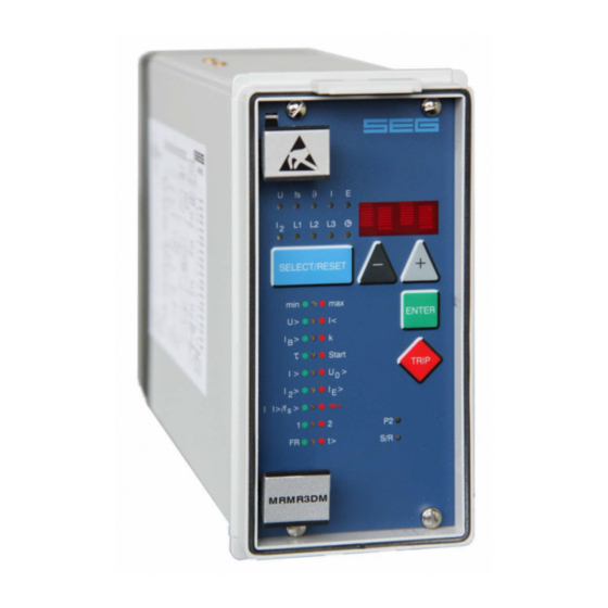
Page 12: Front Plate
Woodward Manual MRN3 GB Front plate Figure 3.4: Front plate MRN3-1 Figure 3.5: Front plate MRN3-2 TD_MRN3_09.08_GB_Rev.New... -
Page 13: Working Principle
Manual MRN3 GB Woodward 4. Working principle Analog circuits The input voltages are galvanically insulated by the input transformers. The noise signals caused by inductive and capacitive coupling are suppressed by an analog R-C filter circuit. The analog voltage signals are fed to the A/D-converter of the microprocessor and transformed to digital signals through Sample- and Hold- circuits. -
Page 14: Selection Of Star Or Delta Connection
Woodward Manual MRN3 GB 4.3.1 Selection of star or delta connection All connections of the input voltage transformers are led to screw terminals. The nominal voltage of the device is equal to the nominal voltage of the input transformers. Dependent on the application the input transformers can be connected in either delta or star. -
Page 15: Principle Of Frequency Supervision
Manual MRN3 GB Woodward Principle of frequency supervision The frequency element of MRN3 protects electrical generators, consumers or electrical operating equipment in general against over- or under frequency. The relay has independent three frequency elements f with a free choice of parameters, with separate adjustable pickup values and delay times. -
Page 16: Vector Surge Supervision (Mrn3-1)
Woodward Manual MRN3 GB Vector surge supervision (MRN3-1) The vector surge supervision protects synchronous generators in mains parallel operation due to very fast decoupling in case of mains failure. Very dangerous are mains auto reclosings for syn- chronous generators. The mains voltage returning after 300 ms can hit the generator in asynchron- ous position. -
Page 17: Measuring Principle Of Vector Surge Supervision
Manual MRN3 GB Woodward 4.6.1 Measuring principle of vector surge supervision When a synchronous generator is loaded, a rotor displacement angle is build between the terminal voltage (mains voltage U1) and the synchronous internal voltage (Up). Therefore a voltage is difference ΔU is built between Up and U1 (Fig. - Page 18 Woodward Manual MRN3 GB The rotor displacement angle ϑ between stator and rotor is depending of the mechanical moving torque of the generator shaft. The mechanical shaft power is balanced with the electrical fielded mains power, and therefore the synchronous speed keeps constant (Fig. 4.5).
- Page 19 Manual MRN3 GB Woodward Figure 4.8: Voltage vector surge As shown in the voltage/time diagram the instantaneous value of the voltage jumps to another val- ue and the phase position changes. This is named phase or vector surge. The MRN3-1 measures the cycle duration. A new measuring is started at each voltage zero pas- sage.
- Page 20 Woodward Manual MRN3 GB Application hint Although the vector surge relay guarantees very fast and reliable detection of mains failures under nearly all operational conditions of mains parallel running alternators, the following borderline cases have to be considered accordingly: a) None or only insignificant change of power flow at the utility connection point during mains failures.
-
Page 21: Voltage Threshold Value For Frequency Measuring
Manual MRN3 GB Woodward Voltage threshold value for frequency measuring At low measuring voltages, e.g. during generator start-up, frequency and vector surge or df/dt- measuring is perhaps not desired. By means of the adjustable voltage threshold value UB<, functions f1 - f3, df/dt or ΔΘ are blocked if the measured voltage falls below the set value. -
Page 22: Operation And Setting
Woodward Manual MRN3 GB 5. Operation and setting Display Function Display shows Pressed Corre- Type of pushbutton sponding relay Normal operation all types Measured operating values Actual measured <SELECT/RESET> one L1, L2, L3, value time for each value f, min, max Min. -
Page 23: Setting Procedure
Manual MRN3 GB Woodward Function Display shows Pressed Corre- Type of pushbutton sponding relay measuring (df/dt for MRN3- Slave address of serial in- 1 - 32 <SELECT/RESET><+><-> terface Baud-Rate 1200-9600 <SELECT/RESET> <+><-> Parity-Check even odd no <SELECT/RESET> <+><-> Recorded fault data: tripping values in <SELECT/RESET><+><->... -
Page 24: System Parameter
Woodward Manual MRN3 GB System parameter 5.3.1 Display of residual voltage U as primary quantity (U prim The residual voltage can be shown as primary measuring value. For this parameter the transformation ratio of the VT has to be set accordingly. If the parameter is set to "sec", the measuring value is shown as rated secondary voltage. -
Page 25: Display Of The Activation Storage (Flsh/Nofl)
Manual MRN3 GB Woodward This difference in settings is required for the fault recorder. If the fault recorder is to be used, the setting must be f = 50 Hz or f = 60 Hz. The different designations "f“ or "v“ have no influence on any of the other functions. - Page 26 Woodward Manual MRN3 GB With the setting B_S2 the blocking input (D8, E8) is used as parameter-set change-over switch. With the setting R_S2 the reset input (D8, E8) is used as parameter-set change-over switch. With the setting B_FR the fault recorder is activated immediately by using the blocking input.
-
Page 27: Protection Parameters
Manual MRN3 GB Woodward Protection parameters 5.4.1 Parameter setting of over- and under voltage supervision The setting procedure is guided by two colored LEDs. During setting of the voltage thresholds the LEDs U<, U<<, U> and U>> are lit green. During setting of the trip delays t and t U>... -
Page 28: Tripping Delays For The Frequency Elements
Woodward Manual MRN3 GB 5.4.4 Tripping delays for the frequency elements Tripping delays t of the four frequency elements can be set independently from t min - 50 s. The minimum tripping delay tf1min of the relay depends upon the number of set measuring... -
Page 29: Parameter Setting Of Frequency Gradient (Mrn3-2)
Manual MRN3 GB Woodward 5.4.6 Parameter setting of frequency gradient (MRN3-2) The pickup value of frequency gradient (parameter df) can be set between 0.2 to 10 Hz/s. The number of measuring repetitions (parameter dt) can be set between 2 - 64 cycles. This parameter defines the number of df/dt measurements, which have to exceed the set value, before tripping. -
Page 30: Adjustment Of The Fault Recorder
Woodward Manual MRN3 GB Adjustment of the fault recorder The MRN3 is equipped with a fault recorder (see chapter 3.7). Three parameters can be deter- mined. 5.5.1 Number of the fault recordings The max. recording time is 16 s at 50 Hz or 13.33 s at 60 Hz. -
Page 31: Additional Functions
Manual MRN3 GB Woodward Additional functions 5.7.1 Setting procedure for blocking the protection functions The blocking function of the MRN3 can be set according to requirement. By applying the aux. voltage to D8/E8, the functions chosen by the user are blocked. Setting of the parameter should be done as follows: •... - Page 32 Woodward Manual MRN3 GB After the assignment mode has been activated, first LED U< lights up green. Now one or several of the four output relays can be assigned to under volt-age element U< as alarm relays. At the same time the selected alarm relays for under voltage element 1 are indicated on the display.
-
Page 33: Indication Of Measuring Values
Manual MRN3 GB Woodward Indication of measuring values 5.8.1 Measuring indication In normal operation the following measuring values can be displayed. • Voltages (LED L1, L2, L3 green) • In star connection all phase-to-neutral voltages • In delta connection all phase-to-phase voltages •... -
Page 34: Unit Of The Measuring Values Displayed
Woodward Manual MRN3 GB 5.8.3 Unit of the measuring values displayed The measuring values can optionally be shown in the display as a multiple of the "sec" rated value (x ln) or as primary current (A). According to this the units of the display change as follows:... -
Page 35: Reset
Manual MRN3 GB Woodward Recorded fault data: Measuring Displayed value Corresponding LED Voltage L1; L2; L3; L1/L2; L2/L3; L3/L1 L1; L2; L3 Frequency f; f min f max f; min; max Frequency changing rate ΔΘ ΔΘ Vektorsprung Time stamp Date:... -
Page 36: Relay Testing And Commissioning
Woodward Manual MRN3 GB 6. Relay testing and commissioning The following test instructions should help to verify the protection relay performance before or dur- ing commissioning of the protection system. To avoid a relay damage and to ensure a correct relay operation, be sure that: •... -
Page 37: Checking The Set Values
Manual MRN3 GB Woodward Checking the set values By repeatedly pressing the push button <SELECT>, all relay set values may be checked. Set value modification can be done with the push button <+><-> and <ENTER>. For detailed information about that, please refer to chapter 4.3 of the description “MR – Digital multifunctional re-lays”. -
Page 38: Example Of Test Circuit
Woodward Manual MRN3 GB Example of test circuit For testing of the MRN3 relay, a three phase volt-age source with adjustable voltage and frequency is required. Figure 6.1 shows an example of a three-phase test circuit energizing the MRN3 relay during test. -
Page 39: Checking The Input Circuits And Measuring Functions
Manual MRN3 GB Woodward 6.5.1 Checking the input circuits and measuring functions Apply three voltages of rated value to the voltage input circuits (terminals A3 - A8) of the relay. Check the measured voltages, frequency and vector surge on the display by pressing the push but- ton <SELECT/RESET>... -
Page 40: Checking The Operating And Resetting Values Of The Over/Under Frequency Functions
Woodward Manual MRN3 GB 6.5.4 Checking the operating and resetting values of the over/under frequency functions Note: Due to frequency changes, vector surge tripping or df/dt - tripping can occur during frequency tests. In order to ensure a trouble-free test procedure, the vector surge function or df/dt function of the re- lay have to be blocked before tests are started. -
Page 41: Checking The External Blocking And Reset Functions
Manual MRN3 GB Woodward Figure 6.2: Test circuit for the vector surge function 6.5.7 Checking the external blocking and reset functions The external blocking input is free programmable by the user. To test the blocking function apply auxiliary supply voltage to the external blocking input of the re- lay (terminals E8/D8). -
Page 42: Primary Injection Test
Woodward Manual MRN3 GB Primary injection test Generally, a primary injection test could be carried out in the similar manner as the secondary in- jection test described above. With the difference that the protected power system should be, in this case, connected to the installed relays under test „on line“, and the test voltages should be injected... -
Page 43: Technical Data
Manual MRN3 GB Woodward 7. Technical data Measuring input circuits Rated data: Nominal voltage U 100 V, 230 V, 400 V Nominal frequency f 40 - 70 Hz Power consumption in voltage circuit: <1 VA Thermal rating: continuously 2 x U... -
Page 44: Setting Ranges And Steps
Woodward Manual MRN3 GB Setting ranges and steps Function Para- Setting range Steps Tolerance meter Transformer (SEC) 1.01...6500 0.01; 0.02; 0.05; 0.1; prim ratio 0.2; 0.5; 1.0; 2.0; 5.0; 10; 20; 50 Rated fre- f = 50 Hz / f = 60 Hz quency Δ/Y... -
Page 45: Interface Parameter
Manual MRN3 GB Woodward 7.3.1 Interface parameter Function Parameter Modbus-Protocol RS485 Open Data Protocol Slave-Address 1 - 32 1 - 32 Baud-Rate* 1200, 2400, 4800, 9600 9600 (fixed) Parity* even, odd, no “even Parity” (fixed) Table 7.2: Interface parameter *only Modbus Protocol 7.3.2 Parameters for the fault recorder... -
Page 46: Order Form
Woodward Manual MRN3 GB 8. Order form Mains decoupling relay MRN3- with voltage-, frequency and vector surge supervision Voltage, frequency and df/dt-supervision Rated voltage 100 V 230 V 400 V Housing (12TE) 19“-rack Flush mounting RS485 Alternatively with Modbus Protocol Technical data subject to change without notice! TD_MRN3_09.08_GB_Rev.New... - Page 47 Manual MRN3 GB Woodward Setting list MRN3 Project: SEG job.-no.: Function group: = Location: + Relay code: - Relay functions: Password: Setting of the parameters System parameter Relay Default Actual type settings settings Function Unit MRN3-1 MRN3-2 Set 1/Set 2 Set 1/Set 2...
- Page 48 Woodward Manual MRN3 GB Fault recorder Default Actual Function Unit settings settings Number of recordings Saving of the recording at the occurrence TRIP Time prior to trigger impulse 0.05 Year setting year Y=00 Month setting month M=00 Day setting D=00...
- Page 49 Manual MRN3 GB Woodward Setting of code jumpers Code jumper Default Actual Default Actual Default Actual settings settings settings settings settings settings Plugged Not plugged No function Code jumper Low/High-range for Reset input Low/High-range for blockage input Default settings Actual settings...
- Page 50 Woodward Manual MRN3 GB Woodward SEG GmbH & Co. KG Krefelder Weg 47 ⋅ D – 47906 Kempen (Germany) Postfach 10 07 55 (P.O.Box) ⋅ D – 47884 Kempen (Germany) Phone: +49 (0) 21 52 145 1 Internet Homepage http://www.woodward-seg.com Documentation http://doc.seg-pp.com...
Need help?
Do you have a question about the MRN3 Series and is the answer not in the manual?
Questions and answers