Table of Contents
Advertisement
Quick Links
Advertisement
Table of Contents

Related Manuals for Woodward MRS1


Summary of Contents for Woodward MRS1
- Page 1 MRS1 - Negative sequence relay Manual MRS1 (Revision A)
- Page 2 Woodward Manual MRS1 GB Woodward Governor Company reserves the right to update any portion of this publication at any time. Information provided by Woodward Governor Company is believed to be correct and reliable. However, no responsibility is as- sumed by Woodward Governor Company unless otherwise expressly undertaken.
-
Page 3: Table Of Contents
Secondary injection test ....................16 6.4.1 Test equipment......................16 6.4.2 Example of test circuit for MRS1 relay ................16 6.4.3 Checking the input circuits and measured values ............16 6.4.4 Checking the operating and resetting values of the relay ..........17 ... -
Page 4: Introduction And Application
Manual MRS1 GB 1. Introduction and application The MRS1 relay is a negative sequence protection relay with universal application. It serves for negative sequence protection of three-phase generators. With a large number of different tripping characteristics and adjustment possibilities, the tripping characteristic can be made suitable for al- most every type of generator with regard to its special thermal time-constant. -
Page 5: Design
/ digital converter. 3.1.2 Output Relays The MRS1 has 4 output relays, one of them with two change-over contacts is used for tripping, the other relays with one change-over contact each are used for indication. ... -
Page 6: Display
Woodward Manual MRS1 GB Display Function Display shows Pressed pushbutton Corresponding Normal operation Measured operating Actual measured value, <SELECT/RESET> L1, L2, L3, I2 values related to I one time for each value Setting values: negative sequence current pickup value <SELECT/RESET>... -
Page 7: Leds
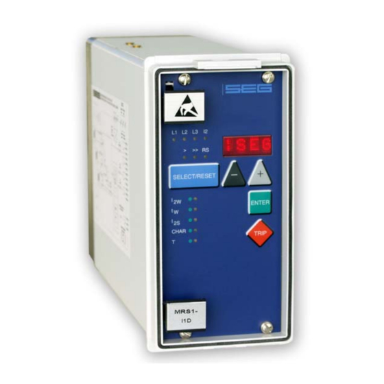
Manual MRS1 GB Woodward Figure 3.1: Front plate LEDs The LEDs L1, L2, L3 and I2 left to the display are bi-colored LED. Green indicates measuring, red fault values. The LED marked with letters RS lights up during setting of the slave address of the device for serial data communication. -
Page 8: Working Principle
Digital circuits The essential part of the MRS1 relay is a powerful microcontroller. All of the operations, from the analog digital convertion to the relay trip decision, are carried out by the microcontroller digitally. The relay program is located in an EPROM (Electrically Programmable Read-Only-Memory). -
Page 9: Principle Of Negative Sequence Protection
Usual values are approx. 10 - 15 % of the load which is permissible with symmetrical load. The negative sequence relay MRS1 has a large number of adjustable tripping characteristics. Protection of almost every type of generator is thereby possible. -
Page 10: Measurement Principle
(Fig. 4.1). Figure 4.2: Three-phase system with unbalanced load Fig. 4.2 shows the current vectors of an asymmetrically loaded generator. The MRS1 relay forms the negative-sequence system by rotation and adding of the current vectors. Tripping takes place according to the adjusted tripping-characteristic. - Page 11 The functional relationship is described graphically in chapter 7.4. In case of an occurrence of un- balanced-load, the thermal load of the generator prior to it, is taken into account. Should after a pickup of MRS1 relay, the I2s value drop, the time elapsed is calculated backwards exponentially. DOK-TD-MRS1 Rev.A...
- Page 12 The time-constant T for the selection of the tripping characteristic can be calculated as follows: = 60 s / 0.16 = 375 s 360 s T = K1 / K The adjustable time-constant on the MRS1 relay amounts to 360 s. For the warning stage I , a somewhat lower value than I (e.g.
-
Page 13: Operations And Settings
Manual MRS1 GB Woodward 5. Operations and settings Adjustable parameters The user can adjust 5 parameters in all: Negative sequence current which leads to a warning Time-delay for the warning signal Continuously permissible negative sequence current CHAR - Tripping characteristic (Inverse-time or definite time) -
Page 14: Rated Frequency
After tripping, the LED "I2" lights up with an additional steady red light. Reset Unit MRS1 has the following three possibilities to reset the display of the unit as well as the output relay at jumper position J3=ON. Manual Reset ... -
Page 15: Relay Testing And Commissioning
Manual MRS1 GB Woodward 6. Relay testing and commissioning The following test instructions should help to verify the protection relay performance before or dur- ing commissioning of the protection system. To avoid a relay damage and to ensure a correct relay operation, be sure that: ... -
Page 16: Secondary Injection Test
Test leads and tools 6.4.2 Example of test circuit for MRS1 relay For testing MRS1 relays, you need usually a three phase current test circuit with adjustable phase shifting to simulate various asymmetrical system conditions. Yet you can also use a single-phase test circuit. -
Page 17: Checking The Operating And Resetting Values Of The Relay
By using an RMS-metering instrument, a greater deviation may be observed if the test current contains harmonics. Because the MRS1 relay measures only the fundamental component of the input signals. The harmonics will be rejected using a DFFT-digital filter. Whereas the RMS- metering instrument measures the RMS-value of the input signals. -
Page 18: Checking The Extern Blocking And Reset Functions
6.4.6 Checking the extern blocking and reset functions By MRS1 relays, the trip element will be inhibited by extern blocking input. To test the blocking function apply auxiliary supply voltage to extern blocking input of the relay (terminals E8/D8). Inject a test current which could cause a tripping. -
Page 19: Technical Data
Manual MRS1 GB Woodward 7. Technical data MRS1 - Digital Multifunctional Relay for negative sequence protection Measuring input circuits Rated data: Nominal current I 1A or 5A Nominal frequency f 50 Hz; 60 Hz adjustable Power consumption in current circuit:... -
Page 20: Tripping Characteristic
Woodward Manual MRS1 GB Tripping characteristic Figure 7.2: Tripping characteristic Output contact ratings Number of relays: Contacts: 2 change-over contacts for trip relay 1 change-over contact for alarm relays DOK-TD-MRS1 Rev.A... -
Page 21: Order Form
Manual MRS1 GB Woodward 8. Order form Negative sequence relay MRS1- Rated current Housing (12TE) 19“-rack Flush mounting Technical data subject to change without notice! DOK-TD-MRS1 Rev.A... - Page 22 Woodward Manual MRS1 GB Setting-list MRS1 Project: Woodward job.-no.: Function group: = Location: + Relay code: - Relay functions: Password: Date: Default Actual Function Unit settings settings Negative sequence current which leads to a warning 0.02 Time delay for I2w Continuously permissible negative sequence current 0.02...
- Page 23 Manual MRS1 GB Woodward DOK-TD-MRS1 Rev.A...
- Page 24 Woodward Manual MRS1 GB Woodward Kempen GmbH Krefelder Weg 47 D – 47906 Kempen (Germany) Postfach 10 07 55 (P.O.Box) D – 47884 Kempen (Germany) Phone: +49 (0) 21 52 145 1 Internet www.woodward.com Sales Phone: +49 (0) 21 52 145 216 or 342 Telefax: +49 (0) 21 52 145 354 e-mail: salesEMEA_PGD@woodward.com...
Need help?
Do you have a question about the MRS1 and is the answer not in the manual?
Questions and answers