Table of Contents
Advertisement
Quick Links
Advertisement
Table of Contents

Related Manuals for Woodward MRP2


Summary of Contents for Woodward MRP2
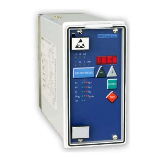
- Page 1 MRP2 - Directional Power Relay (May 2008) Manual MRP2 (Revision New)
- Page 2 Woodward Manual MRP2 GB Woodward Governor Company reserves the right to update any portion of this publication at any time. Information provided by Woodward Governor Company is believed to be correct and reliable. However, no responsibility is as- sumed by Woodward Governor Company unless otherwise expressly undertaken.
-
Page 3: Table Of Contents
Secondary injection test ....................25 6.4.1 Test equipment ......................25 6.4.2 Example of test circuit for MRP2 relay ................ 26 6.4.3 Checking the input circuits and measured values ............27 6.4.4 Checking the operating and resetting values of the relay ........... 27 ... - Page 4 Woodward Manual MRP2 GB 7.3.1 Setting ranges and steps MRP2-1 and MRP2-3 ............31 7.3.2 Setting ranges and steps MRP2-R1 and MRP2-R3 ............ 31 7.3.3 Interface parameters ....................32 Output contact ratings ..................... 32 ...
-
Page 5: Introduction And Application
The power relay MRP2 is used in 3-phase systems for active power measurement. In the single-phase relay type MRP2-1, the load of the three phases is assumed to be symmetrical so that a single phase power measurement can be realized. -
Page 6: Features And Characteristics
Woodward Manual MRP2 GB 2. Features and characteristics Unit MRP2 still has another feature besides those described in the general MR-description, namely: • Measuring of the actual power by means of multiplication and integration of the instantaneous values of current and voltage. -
Page 7: Design
Manual MRP2 GB Woodward 3. Design Connections Figure 3.1: Connection diagram MRP2-1 and MRP2-R1 (Star-/Delta adjustment has to be set to DELTA) Figure 3.2: Connection diagram MRP2-3 and MRP2-R3 (Star-/Delta adjustment has to be set to Y) TD_MRP2_05.08_GB_Rev.New... -
Page 8: Analog Input Circuits
U1 (A3), U2 (A5), U3 (A7) with A8 as star point are each transmitted to the protec- tion device MRP2-3 by means of separate input transformers (star connection). At the single-phase version of unit MRP2-1 the in-put signals are also transmitted via separate in- put transformers: I (B3-B4);... - Page 9 Manual MRP2 GB Woodward Figure 3.4: Front plate MRP2-1 and MRP2-R1 Figure 3.5: Front plate MRP2-3 and MRP2-R3 TD_MRP2_05.08_GB_Rev.New...
-
Page 10: Leds
Measuring values will be indicated on display together with the LEDs P, L1, L2, L3, U and I (refer to chapter 5.3). The MRP2 provides one LED to indicate the power direction (green and red arrow). Green indi- cates generator power, red indicates reverse power. -
Page 11: Working Principle
50 Hz (60 Hz). Digital circuits The essential part of the MRP2 relay is a powerful microcontroller. All of the operations, from the analog digital convertion to the relay trip decision, are carried out by the microcontroller digitally. -
Page 12: Measuring Principle
The current transformers must be designed in such a manner that they are precisely dimensioned for pure reverse power in the lower range especially with the MRP2-R. We therefore recommend the use of measuring transformers which are at least type 1M5. The low energy consumption of the MRP2-R of <0.2 VA has a positive effect on the design of the current transformers. -
Page 13: Operations And Settings
<+><-><ENTER> System reset ⏐SEG <SELECT/RESET> for about 3 s Table 5.1: Possible indication messages on the display The units MRP2-1 and MRP2-R1 with single-phase power measurement have only the LED P available instead of LED L1, L2 and L3 TD_MRP2_05.08_GB_Rev.New... -
Page 14: Setting Procedure
Pr must be set „positive“. In the MRP2-R (reverse power relay with increased precision) unit version, the value for a power increase in forward direction P> can only be set to 0,5 x Pn and must therefore - as a rule - be blocked by means of setting „EXIT“. -
Page 15: Pickup Value For Under Voltage U< Of The Voltage Dependent Reverse Power Element
Manual MRP2 GB Woodward 5.2.2 Pickup value for under voltage U< of the voltage dependent reverse power element When the threshold value of the secondary voltage excitation is being adjusted, the display shows a response value in voltage. The voltage-dependent reverse power element is excited when the device measures a reverse power greater than Pr (set value see 5.2.1) and a secondary voltage... -
Page 16: Y/Δ - Change-Over Of The Input Transformers
Manual MRP2 GB 5.2.4 Y/Δ - Change-over of the input transformers The voltage sensing circuits of the MRP2 may be connected in either star or delta configuration. The relay rated voltage, U , refer to the line-line voltage in the star connection. When the relay is connected in the delta connection the maximum line-to-line voltage must be reduced to 1/√3 x U... -
Page 17: Circuit Breaker Failure Protection T
Manual MRP2 GB Woodward 5.2.5 Circuit breaker failure protection t CBFP The CB failure protection is based on supervision of phase currents during tripping events. Only af- ter tripping this protective function becomes active. The test criterion is whether all phase currents are dropped to <1% x I... -
Page 18: Blocking The Protection Functions And Assignment Of The Output Relays
Assignment of the output relays: Unit MRP2 has five output relays. The fifth output relay is provided as permanent alarm relay for self supervision is normally on. Output relays 1 - 4 are normally off and can be assigned as alarm or trip-ping relays to the power functions which can either be done by using the push buttons on the front plate or via serial interface RS485. - Page 19 Manual MRP2 GB Woodward Definition: Alarm relays are activated at pickup. Tripping relays are only activated after elapse of the tripping delay. The relays are assigned as follows: • LEDs P>, P< and Pr are two-colored and light up green when the output relays are assigned as alarm relays and red as tripping relays.
-
Page 20: Indication Of Measuring Values And Fault Data
LEDs (L1, L2, L3, →←) and the four function LEDs (P>, P<, Pr, U< ) are equipped at MRP2 and MRP2-R1. If, for example a reverse power occurs, first the LEDs L1, L2, L3 will light up. LED Pr lights up at the same time. After tripping the LEDs are lit permanently. -
Page 21: Fault Recorder
When the relay is energized or is energized or trips, all fault data and times are stored in a non- volatile memory manner. The MRP2 is provided with a fault value recorder for max. eight fault events. In the event of additional trippings always the oldest data set is written over. -
Page 22: Reset
Woodward Manual MRP2 GB Reset Unit MRP2 has the following three possibilities to reset the display of the unit as well as the output relays at jumper position J3=ON. Manual Reset • Pressing the push button <SELECT/RESET> for some time (about 3 s). - Page 23 (% of scale) = x5% = 3.62% In the previous example the relay MRP2 has to be adjusted to 4%, so that it responds to a genera- tor reverse-active power of 5%. The more sensitive relay version MRP2-R can be adjusted to 3.7%...
-
Page 24: Relay Testing And Commissioning
Woodward Manual MRP2 GB 6. Relay Testing and commissioning The following test instructions should help to verify the protection relay performance before or dur- ing commissioning of the protection system. To avoid a relay damage and to ensure a correct relay operation, be sure that: •... -
Page 25: Checking The Set Values
Phase-to-phase voltages or phase-to-neutral volt-age will be connected to the relay MRP2-1 when changeover star/delta correction. NOTE! For single phase power relay MRP2-1, if delta connection is chosen, current in phase 1 (I ) should be connected to input terminals B3/B4 and phase-to-phase voltage between phase 1 and phase 2 ) should be connected to input terminals A3/A4. -
Page 26: Example Of Test Circuit For Mrp2 Relay
In figure 6.1 the relay voltage connection is sup-posed to be set to star connection and a single phase test circuit will be used to test a three phase power relay MRP2-3 or a single phase power relay MRP2-1. -
Page 27: Checking The Input Circuits And Measured Values
Manual MRP2 GB Woodward 6.4.3 Checking the input circuits and measured values The active power measured by MRP2 is related to the rated power of the relay P 3 · · √ 3 Inject a current of rated value (1A for I = 1A) in phase 1 (terminals B3-B4) and apply a voltage of Un/ √... -
Page 28: Test Of The Cb Failure Protection
6.4.7 Checking the external blocking and reset functions At MRP2 relays, all relay functions will be inhibited by external blocking input. To test the blocking function: Apply auxiliary supply voltage to the external blocking input of the relay (terminals E8/D8). -
Page 29: Primary Injection Test
Because of its powerful combined indicating and measuring functions, you have still the possibili- ties to test the MRP2 relay in the manner of a primary injection without extra expenditures and time consumption. In actual service, for example, the measured cur-rent and voltage values as well as the measured... -
Page 30: Technical Data
Woodward Manual MRP2 GB 7. Technical data For further information please refer to description "MR-Digital Multifunctional Relays". Measuring input circuits Rated data: Rated current I 1A or 5 A Rated voltage U 100 V, 230 V, 400 V Rated frequency f 40 - 70 Hz Max. -
Page 31: Setting Ranges And Steps
0.2; 0.5; 1.0; 2.0 s 0,01; 0,02; 0,05; 0,1 s ±1% bzw. ±10 ms 0,1...1,6 s; EXIT CBFP CBFP Table 7.1: Setting ranges and steps MRP2-1 and MRP2-3 7.3.2 Setting ranges and steps MRP2-R1 and MRP2-R3 Function Parameter Setting range Step Tolerance 0.001...0.5 x P... -
Page 32: Interface Parameters
Woodward Manual MRP2 GB 7.3.3 Interface parameters Function Parameter Modbus-Protocol RS485 Open Data Protocol Slave-Address 1 - 32 1 - 32 Baud-Rate 1200, 2400, 4800, 9600 9600 (fixed) Parity even, odd, no „even Parity“ (fixed) Table 7.3: Interface parameter Output contact ratings... -
Page 33: Order Form
Manual MRP2 GB Woodward 8. Order form Directional power relay MRP2- Measuring of reverse power only (2-steps; sensitive) Power measuring 1-phase 3-phase Rated current Rated voltage: 100 V/110 V 230 V 400 V Housing (12TE) 19“-rack Flush mounting Optionally with Modbus protocol... - Page 34 Woodward Manual MRP2 GB Setting list MRP2 Project: SEG job.-no.: Function group: = Location: + Relay code: - Relay functions: Password: Date: Setting of the parameters Default Actual Function Unit settings settings Δ/Y Input Transformer Connection DELTA P> pickup value for overload 0.005/0.001...
- Page 35 Manual MRP2 GB Woodward Setting of code jumpers Code jumper Default set- Actual set- Default set- Actual set- Default Actual set- ting ting ting ting setting ting Plugged No function Not plugged Assignment of the output relays: Function Relay 1...
- Page 36 Woodward Manual MRP2 GB AvK Generátory s.r.o. ul. 4. května 175 755 01 Vsetín (Czech Republic) Tel.: +420 571 413 322 http://www.woodward-seg.cz info@woodward-seg.cz TD_MRP2_05.08_GB_Rev.New...
Need help?
Do you have a question about the MRP2 and is the answer not in the manual?
Questions and answers