
Subscribe to Our Youtube Channel
Related Manuals for Alfa IN PEGAS 201 MIG SYN PFC


Summary of Contents for Alfa IN PEGAS 201 MIG SYN PFC
-
Page 1: Welding Machine
WELDING MACHINE PEGAS 201 MIG SYN PFC OPERATING MANUAL ALFA IN a.s. © www.alfain.eu PEGAS 201 MIG SYN PFC manual EN 04... -
Page 2: Table Of Contents
MAIN MENU .................... 10 GETTING STARTED MIG/MAG .............. 13 GETTING STARTED TIG ................ 20 GETTING STARTED MMA ..............21 10. ROUTINE MAINTENANCE & INSPECTION .......... 21 11. STATEMENT OF WARRANTY .............. 22 12. DISPOSAL ..................... 23 ALFA IN a.s. © www.alfain.eu... -
Page 3: Introduction
3/23 1. INTRODUCTION Congratulations on your new ALFA IN product. We are proud to have you as our customer and will strive to provide you with the best service and reliability in the industry. This operating manual has been designed to instruct you on the correct use and operation of your ALFA IN product. -
Page 4: Safety Instructions And Warnings
The operator must be aware of all the special regulations which he needs to conform to when welding in enclosed spaces with a high risk of explosion. To prevent electric shock, we strongly suggest the following rules: a. Do not work in a damp or humid environment. ALFA IN a.s. © www.alfain.eu... - Page 5 NOTE: Device complies with IEC 61000-3-12. ELECTROMAGNETIC COMPATIBILITY The welding device is in terms of interference designed primarily for industrial areas. It meets the requirements of EN 60974-10 class A and it isn’t designed ALFA IN a.s. © www.alfain.eu...
-
Page 6: Technical Data
Spool diameter Spool weight ALFA IN continuously strives to produce the best product possible and therefore reserves the right to change, improve or revise the specifications or design of this or any product without prior notice. Such updates or changes do not entitle the buyer of equipment previously sold or shipped to the corresponding changes, updates, improvements or replacement of such items. -
Page 7: Equipment
7/23 4. EQUIPMENT MODELS Item No Description 5.0284 PEGAS 201 MIG SYN PFC ACCESSORIES TO ORDER Item No. Description SGB25-3 Torch PARKER SGB 250 3m SGB25-4 Torch PARKER SGB 250 4m SGB25-5 Torch PARKER SGB 250 5m 17FSL4S Torch PARKER SGT 17 4m 35-50 FX S... -
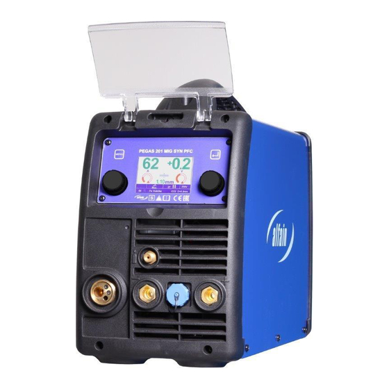
Page 8: Main Parts Of The Machine
5. MAIN PARTS OF THE MACHINE Fig. PEGAS 201 Pos. Description MIG/MAG torch connector Quick connector (-) of welding cables or TIG torch Gas connector for TIG torch Knob Display Knob TIG torch control connector ALFA IN a.s. © www.alfain.eu... - Page 9 Gas connector Handle Spool holder Switch Spool Gun Terminals of change polarity MIG/MAG torch Wire feeder WIRE FEEDER Fig. 2 Wire feeder Pos. Description Nut of pressure arm Pressure arm Inlet liner EURO connector Roll ALFA IN a.s. © www.alfain.eu...
-
Page 10: Main Menu
= 22 mm b = 30 mm Groove type Wire diameter Item No 0,6-0,8 2187 Steel 0,8-1,0 2188 0,8-1,0 2270 Aluminium 0,8-1,0 2318 Flux core 1,0-1,2 2319 6. MAIN MENU Fig. 3 Main Menu ALFA IN a.s. © www.alfain.eu... - Page 11 Use the button in the upper right part of the panel to get to the settings of welding current and voltage. To change these parameters rotate knobs A4 and A6. Fig. 5 Welding parameters selection ALFA IN a.s. © www.alfain.eu...
- Page 12 (Default) (Default) (Default) Two/four Stroke 2T/4T (2T) 2T/4T (2T) Burn Back 0-10 (0) Slow Feed 0-10 (0) Pre Flow 0-2 s (0 s) Post Flow 0-10 (0 s) 0-10 (0 s) ALFA IN a.s. © www.alfain.eu...
-
Page 13: Getting Started Mig/Mag
Getting started must be consistent with technical data and conditions of use. CHOOSING THE FEEDING ROLL In all machines (ALFA IN MIG / MAG) rolls with two grooves are used. These grooves are intended for two different wire diameters (e.g. 0,8 and 1,0 mm). - Page 14 (it will avoid excessive release of wire). However, too tight brake needlessly strains the feeding mechanism and thus slippage may occur in the wire rolls. Pos. Description Spool Holder Nut Spool Holder It is not for this welder Fig. 10 Spool holder ALFA IN a.s. © www.alfain.eu...
- Page 15 Press the torch button and the welding wire is fed into the torch. After coming off from the torch tube, screw the current nozzle and gas nozzle Before welding, spray the area in a gas hose and current nozzle with a separation spray, to prevent damage. ALFA IN a.s. © www.alfain.eu...
- Page 16 (For example, if you want to weld steel by full wire with diameter 0,8 mm and if you have available mixed gas 82% Ar + 8% CO2. This is program number 01). 2. Select the synergic parameter by knob A4 and then press the knob A4 for confirmation. ALFA IN a.s. © www.alfain.eu...
- Page 17 Table of approximate parameter settings ADJUSTING THE MACHINE FOR ANOTHER WIRE DIAMETER In all machines ALFA IN MIG / MAG are used rolls with two grooves. These grooves are intended for two different wire diameters (e.g. 0,8 a 1,0 mm). Groove can be replaced by removing the rolls and rotating them, or use a different roll grooves with required dimensions.
- Page 18 5. Make sure you fasten the terminals properly. 6. Connect the ground cable to the quick connector (+). Fig. 13 Terminals for changing the polarity of the MIG/MAG torch Pos. Description Upper terminal (+) Middle terminal Bridge Lower terminal (-) ALFA IN a.s. © www.alfain.eu...
- Page 19 Fig. 14 Customization of the feed for the aluminium wire Pos. Description EURO connector Rolls Liner terminal for 4,0mm, 4,7mm outer diameter O-ring 3,5 x1, 5mm to prevent escape of gas Liner tefl. Sustain pipe for teflon and plastic liner ALFA IN a.s. © www.alfain.eu...
-
Page 20: Getting Started Tig
Use the knob A4 to adjust the welding current. Use the potentiometer to adjust the time of Slope down. 8. In submenu of welding parameters settings you can change values of Pre Gas time and Post Gas time. ALFA IN a.s. © www.alfain.eu... -
Page 21: Getting Started Mma
4. To clean the welder, disconnect it from the mains supply voltage then open the enclosure and use a vacuum cleaner to remove any accumulated dirt and dust. The welder should also be wiped clean. If necessary, solvents that are recommended for cleaning electrical apparatus may be used. ALFA IN a.s. © www.alfain.eu... -
Page 22: Statement Of Warranty
3. ALFA IN will repair or replace, at its discretion, any warranted parts or components that fail due to defects in material or workmanship within the warranty period. -
Page 23: Disposal
NOTE Warranty repairs must be performed by either an ALFA IN Service Centre, an ALFA IN distributor or an Authorised Service Agent approved by the company ALFA IN. As a warranty list serves proof of purchase (invoice) on which is the serial number of the machine.
Need help?
Do you have a question about the PEGAS 201 MIG SYN PFC and is the answer not in the manual?
Questions and answers