Sign In
Upload
Manuals
Brands
ST Manuals
Motherboard
STM32H747I-DISCO
ST STM32H747I-DISCO Manuals
Manuals and User Guides for ST STM32H747I-DISCO. We have
2
ST STM32H747I-DISCO manuals available for free PDF download: User Manual
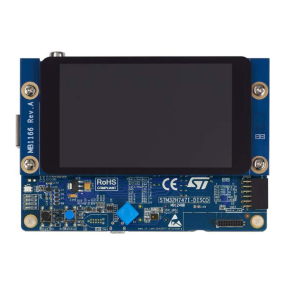
ST STM32H747I-DISCO User Manual (61 pages)
Discovery kit
Brand:
ST
| Category:
Motherboard
| Size: 1.75 MB
Table of Contents
Table of Contents
2
Features
6
Ordering Information
7
Product Marking
7
Codification
8
Development Environment
8
Development Toolchains
8
System Requirements
8
Demonstration Software
8
Table 2. Codification Explanation
8
Delivery Recommendations
9
Hardware Layout and Configuration
10
Figure 4. STM32H747I-DISCO Hardware Block Diagram
10
Figure 5. STM32H747I-DISCO Board Layout (Top View)
11
Figure 6. STM32H747I-DISCO Board Layout (Bottom View)
12
Figure 7. STM32H747I-DISCO Board Mechanical Dimensions (Top View)
13
Stlink-V3E
14
Drivers and Firmware Upgrade
14
Power Supply
14
Supplying the Board through STLINK-V3E USB Port
15
Using STLINK-V3E Along with Powering through External Power
15
SMPS/LDO Power Supply
16
Table 3. Power-Supply Related Jumper and Solder Bridge Settings
17
Clock References
18
Reset Source
18
Audio
18
Digital Microphone
19
USB OTG HS Port
19
STM32H747I-DISCO as USB Device
19
Table 4. Digital Microphone-Related Jumper Settings
19
STM32H747I-DISCO as USB Host
20
Ethernet
20
Sdram
20
Quad-SPI Flash Memory
20
Virtual COM Port
20
User Leds
21
Physical Input Devices
21
Connectors
22
USB OTG HS Micro-AB Connector CN1
22
Table 5. USB OTG HS Micro-AB Connector CN1
22
Figure 8. USB OTG HS Micro-AB Connector CN1
22
STLINK-V3E USB Micro-B Connector CN2
23
SPDIF Input RCA Connector CN3
23
STLINK-V3E MCU Programming Header CN4
23
Table 6. USB Micro-B Connector CN2
23
Table 7. SPDIF Input RCA Connector CN3
23
Table 8. STLINK-V3E MCU Programming Header CN4
23
Figure 9. USB Micro-B Connector CN2
23
Arduino™ uno V3 Connectors CN5, CN6, CN8 and CN9
24
Table 9. Arduino™ uno V3 Compatible Connectors
24
Ethernet RJ45 Connector CN7
25
Audio Blue Jack (Line In) Connector CN10
25
Table 10. USB Micro-B Connector CN2
25
Figure 10. Ethernet RJ45 Connector CN7 (Front View)
25
Audio Green Jack (Line Out) Connector CN11
26
Table 11. Audio Jack Connector CN11 (on Board)
26
Figure 11. Stereo Headset with Microphone Jack CN11
26
Microsd Card Connector CN12
27
Table 12. Microsd Connector CN12
27
Figure 12. Microsd Connector CN12
27
STDC14 Connector CN13
28
Table 13. STDC14 Debugging Connector CN13
28
Figure 13. STDC14 Debugging Connector CN13 (Top View)
28
External 5 V USB Micro-B Connector CN14
29
DSI LCD Connector CN15 (MIPI)
29
Table 14. USB Micro-B Connector CN14
29
Figure 14. USB Micro-B Connector CN14
29
Figure 15. DSI LCD Display Connector CN15
29
Table 15. DSI LCD Module Connector CN15
30
TAG Connector CN16
31
Audio Connector CN17
31
Table 16. TAG Connector CN16
31
Table 17. Audio Connector CN17
31
Figure 16. TAG Connector CN16
31
Camera Module Connector P1
32
Table 18. Camera Module Connector P1
32
Figure 17. Camera Module Connector P1 (Front View)
32
Stmod+ Connector P2
33
Table 19. Stmod+ Connector P2
33
Figure 18. Stmod+ Connector P2
33
Pmod Connector P3
34
Table 20. Pmod Connector P3
34
Figure 19. Pmod Connector P3
34
Schematic Diagrams
35
Figure 20. Overall Schematics for the Board
35
Figure 21. STM32H747I-DISCO MCU
35
Figure 22. Power Supply
35
Figure 23. SDRAM Memory Device
35
Figure 24. Audio Codec Device
35
Figure 25. DSI LCD and Camera Connector
35
Figure 26. Ethernet
35
Figure 27. Quad-SPI Flash Memory Devices
35
Figure 28. Physical Control Peripherals and Microsd™ Card
35
Appendix A STM32H747I-DISCO I/O Assignment
51
Table 21. STM32H747I-DISCO I/O Assignment
51
Appendix B Stmod+ GPIO Sharing and Multiplexing
59
Table 22. Stmod+ GPIO Sharing and Multiplexing
59
Revision History
60
Table 23. Document Revision History
60
Advertisement
ST STM32H747I-DISCO User Manual (51 pages)
Discovery kit with STM32H747XI MCU
Brand:
ST
| Category:
Microcontrollers
| Size: 1.45 MB
Table of Contents
Figure 1. STM32H747I-DISCO Top View
1
Figure 2. STM32H747I-DISCO Bottom View
1
Figure 3. STM32H747I-DISC1 Top View
1
Table of Contents
2
Features
7
Ordering Information
8
Codification
8
Table 1. List of Available Products
8
Table 2. Codification Explanation
8
Development Environment
9
System Requirements
9
Development Toolchains
9
Delivery Recommendations
9
Hardware Layout and Configuration
10
Figure 4. STM32H747I-DISCO Hardware Block Diagram
10
Figure 5. STM32H747I-DISCO Board Layout (Top View)
11
Figure 6. STM32H747I-DISCO Board Layout (Bottom View)
12
Figure 7. STM32H747I-DISCO Board Mechanical Dimensions (Top View)
13
Stlink-V3E
14
Drivers and Firmware Upgrade
14
Power Supply
14
Supplying the Board through STLINK-V3E USB Port
15
Using STLINK-V3E Along with Powering through External Power
15
SMPS/LDO Power Supply
16
Table 3. Power-Supply Related Jumper and Solder Bridge Settings
17
Clock References
18
Reset Source
18
Audio
18
Digital Microphone
19
USB OTG HS Port
19
STM32H747I-DISCO as USB Device
19
Table 4. Digital Microphone-Related Jumper Settings
19
STM32H747I-DISCO as USB Host
20
Ethernet
20
Table 5. Ethernet Related Solder Bridge and Resistor Settings
20
Sdram
21
Quad-SPI Flash Memory
21
Virtual COM Port
21
User Leds
21
Physical Input Devices
21
Connectors
22
USB OTG HS Micro-AB Connector CN1
22
Table 6. USB OTG HS Micro-AB Connector CN1
22
Figure 8. USB OTG HS Micro-AB Connector CN1
22
STLINK-V3E USB Micro-B Connector CN2
23
SPDIF Input RCA Connector CN3
23
STLINK-V3E MCU Programming Header CN4
23
Table 7. USB Micro-B Connector CN2
23
Table 8. SPDIF Input RCA Connector CN3
23
Table 9. STLINK-V3E MCU Programming Header CN4
23
Figure 9. USB Micro-B Connector CN2
23
ARDUINO ® uno V3 Connectors CN5, CN6, CN8 and CN9
24
Table 10. ARDUINO ® uno V3 Compatible Connectors
24
Ethernet RJ45 Connector CN7
25
Audio Blue Jack (Line In) Connector CN10
25
Table 11. USB Micro-B Connector CN2
25
Figure 10. Ethernet RJ45 Connector CN7 (Front View)
25
Audio Green Jack (Line Out) Connector CN11
26
Table 12. Audio Jack Connector CN11 (on Board)
26
Figure 11. Stereo Headset with Microphone Jack CN11
26
Microsd™ Card Connector CN12
27
Table 13. Microsd™ Connector CN12
27
Figure 12. Microsd™ Connector CN12
27
STDC14 Connector CN13
28
Table 14. STDC14 Debugging Connector CN13
28
Figure 13. STDC14 Debugging Connector CN13 (Top View)
28
External 5 V USB Micro-B Connector CN14
29
Dsi
29
Table 15. USB Micro-B Connector CN14
29
Figure 14. USB Micro-B Connector CN14
29
Figure 15. DSI ® LCD Module Connector CN15
29
Table 16. DSI ® LCD Module Connector CN15
30
TAG Connector CN16
31
Audio Connector CN17
31
Table 17. TAG Connector CN16
31
Table 18. Audio Connector CN17
31
Figure 16. TAG Connector CN16
31
Camera Module Connector P1
32
Table 19. Camera Module Connector P1
32
Figure 17. Camera Module Connector P1 (Front View)
32
Stmod+ Connector P2
33
Table 20. Stmod+ Connector P2
33
Figure 18. Stmod+ Connector P2
33
Pmod™ Connector P3
34
Table 21. Pmod™ Connector P3
34
Figure 19. Pmod™ Connector P3
34
STM32H747I-DISCO I/O Assignment
35
Table 22. STM32H747I-DISCO I/O Assignment
35
STM32H747I-DISCO Discovery Kit Information
43
Product Marking
43
STM32H747I-DISCO Product History
44
Table 23. Product History
44
Board Revision History
46
Table 24. Board Revision History
46
Federal Communications Commission (FCC) and ISED Canada Compliance Statements
47
FCC Compliance Statement
47
Part 15.19
47
Part 15.21
47
Part 15.105
47
ISED Compliance Statement
47
CE Conformity
48
Warning
48
Table 25. Stmod+ GPIO Sharing and Multiplexing
49
Table 26. Document Revision History
50
Advertisement
Related Products
ST STM32H747I-EVAL
ST STM32H757I-EVAL
ST STM32H747XI MCU
ST STM32H7B3I-EVAL
ST STM32H7 Nucleo-144
ST STM32H735G-DK
ST STM32H753I-EVAL
ST STM32H743I-EVAL
ST STM32H5
ST STM32MP157A-EV1
ST Categories
Motherboard
Computer Hardware
Microcontrollers
Control Unit
Controller
More ST Manuals
Login
Sign In
OR
Sign in with Facebook
Sign in with Google
Upload manual
Upload from disk
Upload from URL