Table of Contents
Advertisement
Quick Links
User Guide
Robotic and Manual Pan
and Tilt Heads
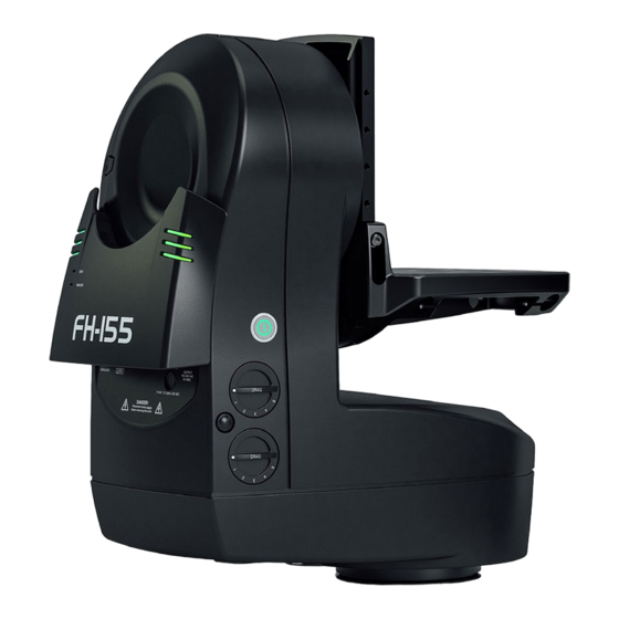
FH155 Manual
FH155 Manual StarTracker
FH155 Manual VR
FH155 Manual VR StarTracker
FHR155 Robotic
FHR155 Robotic StarTracker
FHR155 Robotic VR
FHR155 Robotic VR StarTracker
EN
Part No. V4155-0001
Part No. V4155-0011
V4155-0002
V4155-0012
V4155-0003
V4155-0013
V4155-0004
V4155-0014
www.vinten.com
Advertisement
Table of Contents

Related Manuals for Vinten FH155 Manual


Summary of Contents for Vinten FH155 Manual
- Page 1 User Guide Robotic and Manual Pan and Tilt Heads FH155 Manual FH155 Manual StarTracker FH155 Manual VR FH155 Manual VR StarTracker FHR155 Robotic FHR155 Robotic StarTracker FHR155 Robotic VR FHR155 Robotic VR StarTracker Part No. V4155-0001 Part No. V4155-0011 V4155-0002...
- Page 2 Copyright © 2019 All rights reserved. Original Instructions: English All rights reserved throughout the world. No part of this publication may be stored in a retrieval system, transmitted, copied or reproduced in any way, including, but not limited to, photocopy, photograph, magnetic or other record without the prior agreement and permission in writing of the Vitec Group Plc.
-
Page 3: Table Of Contents
Contents Safety and Warnings . . . . . . . . . . . . . . . . . . . . . . . . 2 Regular Checks. -
Page 4: Safety And Warnings
Safety and Warnings Important information on the safe installation and operation of Health and Safety the product . Read this information before operating the product . For your personal safety, read these instructions . Do not operate WARNING! Risk of personal injury or injury to the product if you do not understand how to use it safely . - Page 5 If the AC cable is damaged, the product CAUTION! Do not use solvent or oil-based cleaners, must be returned to Vinten for repair. abrasives or wire brushes to remove accumulations of CAUTION! Only use the power cable specified for the dirt as these damage the protective surfaces.
- Page 6 70 kg (154 lb). Camera operators can remotely control collisions or injury to personnel. the head pan and tilt axes, and the lens zoom and focus using Vinten If personnel are too close to a head or pedestal that is about to move, control systems.
-
Page 8: Components And Connections
Components and Connections 12 13 1 ......StarTracker camera fitting location 11 ..........Lanc 12 . -
Page 9: Box Contents
NI ........3/8” head fixing bolts, x4 NI ......Vinten spanner (for head bolts) NI . -
Page 10: Installation
Part No . Mount or Adaptor and head setup, a second large cable management bracket (see below) can also be fitted. Vinten HD Quickfix® 3490-3 Vinten HD tripods Camera and head connecting cables should be dressed and secured Adaptor to the bracket(s) to provide strain relief for the connectors. -
Page 11: Mounting The Pan Bar Assembly (Fh-155)
AUTO. Robotic mode must be initiated rosette mountings. from the control panel. Mount the head to the HD tripod using either a Mitchell Centre Screw (spider adaptor) and key or a Vinten Quickfix® adaptor. See Page 8 Mounting Supports and Adaptors... -
Page 12: Mitchell Centre Screw (3724-3)
Installation Mitchell Centre Screw (3724-3) Quickfix Adaptor (V4096-1013) Using a 5/64” Allen key, attach the Mitchell key to the head base with The base of the FH-155 features a groove that can be used to mount two 6-32 UNC screws, then use a 5/16” Allen key to attach the centre the head using a Quickfix adaptor. -
Page 13: Locking / Unlocking The Camera Cradle
Installation Locking / Unlocking the Camera Cradle Adjusting the Camera Cradle The FH-155 is delivered with the camera cradle attached. Note that WARNING! The tilt lock MUST be engaged before the cradle is set to the highest setting during transport. installing or adjusting the camera or payload The maximum payload is 70 kg (154 lb). - Page 14 Installation Adjusting the backplate Adjusting the mounting plate (A) Stepped adjustment– Using a 5 mm Allen key, remove (B) Stepped adjustment – Adjust the mounting plate by the three centre screws and pull the camera cradle off the tilt removing the two side screws and washers and moving the plate mounting.
-
Page 15: Adjusting The Horizon Level
Installation Adjusting the Horizon Level Mounting the Camera Using a 5 mm Allen key, tighten the jacking screw underneath the Apply the tilt lock. mounting plate to adjust the horizon level of the payload. Loosen the Using a 5 mm Allen jacking screw before adjusting the height of the mounting plate. -
Page 16: Balancing The Head
Installation Balancing the Head The FH head range is designed to allow the camera and payload to swing about its own Centre of Gravity (C of G), as opposed to balancing with the use of springs or cams. The camera and payload If the camera cradle stops in are mounted onto the camera cradle so the resulting C of G aligns a horizontal position (camera... -
Page 17: Adjusting The Centre Of Gravity (C Of G)
Installation Adjusting the Centre of Gravity (C of G) If the camera cradle tilts backwards (points upward), then the camera must be moved towards the front of the head (fore). CAUTION! Risk of damage to equipment. Be prepared to prevent the camera and cradle from falling away suddenly. Tilt the camera approx. -
Page 18: Electrical Connections
Installation Electrical Connections If the camera moves back towards the horizontal position when released, the payload is mounted too low—raise the camera cradle. CAUTION! Connect the head to the power source using the attached power cable only . Ethernet cables must be rated at Cat5e with screened RJ45 connectors . -
Page 19: Cable Management
Installation Cable Management Powering Up To ensure a safe and tidy installation, all cables connected to the WARNING! Ensure that all personnel are clear from the head should be dressed and secured using the cable management robotic equipment before powering up. bracket supplied. -
Page 20: Operation
Operation Operation Manual Mode (FH models only) Operating the Drags Switching to Manual Both the pan and tilt axes on the FH models offer drag using the servo motors. The drag is continuously adjustable from low to high in The head can be operated in manual mode by a camera operator both PAN and TILT by rotating the appropriate dial;... -
Page 21: Regular Checks
Maintenance Maintenance Regular Checks Changing the Fuse Routine Use WARNING! Risk of electric shock. Disconnect the power cable. Fuses must only be changed During use, check the following regularly: by a trained and competent person. Once a month check the balance of the camera and payload and adjust if necessary. -
Page 22: Troubleshooting
Troubleshooting Fault Check Action Power supplied, but the camera See “Locking / Unlocking the Camera Check that the tilt lock is disengaged cradle is not moving Cradle” on page 11 Check the power switch is ON See “Powering Up” on page 17 Ensure that the power and Ethernet cables See “Electrical Connections”... -
Page 23: Specifications
Specifications Physical Data FH-155 FHR-155 Max. Payload 70 kg (155 lb) 70 kg (155 lb) Cradle Standard Standard Height 490 mm (19.3 in.) 490 mm (19.3 in.) Length 436 mm (17.2 in.) 436 mm (17.2 in.) Width 235 mm (9.3 in.) 235 mm (9.3 in.) Weight 18 kg (39.6 lb) w/o cradle / 22.4 kg (49.3 lb) with cradle... -
Page 24: General Notes
General Nots Compliance General Purpose Connector Declaration of Conformity The 26-pin, female GP I/O connector (see page 14) can be configured and enabled in Advanced Configuration Tool. It can be used to connect a Camera Control Unit (CCU) or for powering auxiliary devs. Vitec Production Solutions Limited declares that this The pin-outs for the connector are given in the table below. - Page 25 FCC Declaration of Conformity FH Models FHR Models This product complies with Part 15 of the FCC Rules. Operation is subject to the following two conditions: V4155-0001 V4155-0011 V4155-0002 V4155-0012 (1) This product may not cause harmful interference. V4155-0003 V4155-0013 (2) This product must accept any interference received, including V4155-0004 V4155-0014...
- Page 28 Publication No. V4155-4980/0 www.vinten.com...
Need help?
Do you have a question about the FH155 Manual and is the answer not in the manual?
Questions and answers