
Subscribe to Our Youtube Channel
Related Manuals for Renishaw RTP20


Summary of Contents for Renishaw RTP20
- Page 1 RTP20 user's guide www.renishaw.com RTP20 user's guide Documentation part number: H-1000-5116-02-C Issued 07 2019...
-
Page 2: General Information
Renishaw distributor. Warranty Renishaw plc warrants its equipment for a limited period (as set out in our Standard Terms and Conditions of Sale) provided that it is installed exactly as defined in associated Renishaw documentation. Prior consent must be obtained from Renishaw if non-Renishaw equipment (e.g. interfaces and/or cabling) is to be used or substituted. Failure to comply with this will invalidate the Renishaw warranty. - Page 3 Non-corrugated fibreboard Outer box Corrugated fibreboard Packaging insert Corrugated fibreboard Patents Features of the RTP20 system and associated products, equipment and techniques are the subjects of one or more of the following patents and patent applications: CN1695036B EP1546644 JP4361016 US7293365...
-
Page 4: Product Compliance
RTP20 user's guide www.renishaw.com Product compliance EU declaration of conformity Contact Renishaw plc or visit www.renishaw.com/EU for the full EU declaration. REACH regulation Information required by Article 33﴾1﴿ of Regulation ﴾EC﴿ No. 1907/2006 ﴾“REACH”﴿ relating to products containing substances of very high concern (SVHCs) is available at: www.renishaw.com/REACH... -
Page 5: References And Associated Documents
RTP20 user's guide www.renishaw.com References and associated documents The following Renishaw documents are referred to in this document or may be a source of further relevant information. They can easily be acquired from Renishaw web site www.renishaw.com. Title Document number... -
Page 6: System Description
NOTE: The red LED on the front of the head indicates probe status, and can be controlled by either the CMM or a Renishaw probe interface. Conventionally LED ON indicates probe seated (armed), and LED OFF indicates probe triggered. - Page 7 RTP20 user's guide www.renishaw.com RTP20 Specification Measuring performance Positional repeatability ﴾2σ﴿ 2 μm ﴾0.00008 in﴿ (At stylus tip with TP20 standard force module and 10 mm (0.39 in) stylus length) Positional repeatability ﴾2σ﴿ 3 μm ﴾0.00012 in﴿ (At stylus tip with EM2 94.5 mm (3.72 in) extended module and stylus 10 mm (0.39 in) long).
- Page 8 RTP20 user's guide www.renishaw.com Dimensions Issued 07 2019...
-
Page 9: Installation
For optimum shielding against EM phenomena, it is recommended that the shank is grounded to the same electrical point as the control system. Custom designed mountings are available, subject to approval from Renishaw's Custom Products Department. Please contact your supplier or Renishaw for further information. -
Page 10: Operation
Preparing RTP20 for use To prepare RTP20 for use, the pivot pole must be correctly fitted to the CMM table to ensure unobstructed operation of the probe head. The pole consists of three sections; a fixing stud, middle stem and upper pole section which has the pivot sphere at its tip. The pole sections must be fitted using the torque tool (supplied) to ensure the pole does not become loose during operation. - Page 11 Prior to initial use, RTP20 is locked in the A, 0 and B, 0 position to enable the OEM supplied software to define the pivot pole sphere location at eight default positions for RTP20. This is done by calibrating four angles in the A-axis and four angles in the B-axis. Whilst a small degree of misalignment can be accommodated by head/cup geometry, this should be minimised where possible and the first moves should be carried out slowly to confirm clearances.
- Page 12 The Renishaw TP20 probe modules incorporate a kinematic coupling, which ensures highly repeatable stylus tip positioning. The range of modules comprises 5-way versions with length or trigger force options and a 6-way version. Probe modules fit directly onto the RTP20 kinematic mount. It is possible to change TP20 modules with different stylus configurations without re-qualification.
- Page 13 3.7 mm 2.4 mm 4.5 mm 4 mm 4 mm displacement Overtravel 1.5 mm displacement - * The probe module may detach if this value is exceeded NOTE: The use of cranked styli with RTP20 is not recommended. Issued 07 2019...
- Page 14 Each probe module houses the touch-trigger mechanism that carries the stylus assembly. The module provides overtravel in the X, Y and Z axes. The M2 stylus mounting is compatible with Renishaw's comprehensive range of M2 styli. Electrical contact pins automatically complete the probe circuit.
- Page 15 TP20 module selector Seven versions of the TP20 probe module can be used with the RTP20, they can be identified by the end cap colour. 1. Low force (LF) probe module (green cap) 2. Standard force (SF) probe module (black cap) 3.
- Page 16 1. Select the probe module with the correct trigger force rating for the application (see 'TP20 module selector' section). 2. Fit the stylus to the probe module, first hand tightening then using the S7 stylus tool (supplied) for final tightness. Renishaw GF styli require an S20 spanner.
- Page 17 Fitting the probe module with stylus on the RTP20 1. Examine all mating faces for cleanliness. Where necessary, clean the surfaces with the Renishaw CK200 kit (supplied). 2. The TP20 module and kinematic mount are marked with three unique alignment marks. When offering the TP20 up to the probe head, ensure that similar marks are aligned with each other.
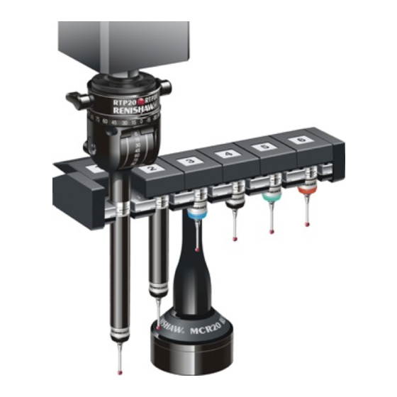
- Page 18 Two Renishaw TP20 probe modules (probe module combination supplied will depend on part number of kit) The MCR20 probe module changing rack, which can be easily mounted onto a CMM using the Renishaw SCR200 mounting kit and location piece, is designed to securely hold stored probe modules for automatic changing, and to protect these stored probe modules from airborne contaminants that may be present within the working environment.
- Page 19 RTP20 user's guide www.renishaw.com MCR20 probe kit Part number number A-1371-0261 A-1371-0262 A-1371-0263 A-1371-0264 A-1371-0265 A-1371-0266 A-1371-0267 A-1371-0268 Mounting the MCR20 onto the CMM To mount the MCR20 probe module change rack onto your CMM, carry out the following procedure: CAUTION: For optimum crash protection, it is recommended that the MCR20 is mounted as close as possible to the extreme edge of the CMM operating envelope.
- Page 20 NOTES: Renishaw recommends that datuming of the MCR20 is performed using the Renishaw PS2R stylus supplied. If a different stylus is to be used, the length (L) must be either 20 mm or 30 mm and the appropriate ball radius (R) must be used to calculate offsets.
-
Page 21: Fault Finding
Fault finding RTP20 CAUTION: RTP20 is designed for automated operation under direct control of the CMM software. To avoid possible collision during use, RTP20 must not be unlocked, re-orientated or locked by hand during normal operation. Poor measuring performance... - Page 22 Loss of measuring accuracy Possible causes Remedy Mounting not secure Check that the RTP20 is correctly mounted on the shank and that the screws are secure. Check clamping mechanism in the CMM quill is secure for RTP20. RTP20 not fully locked Ensure that the thumbwheel / lock lever is turned fully clockwise.
-
Page 23: Maintenance
Maintenance of the TP20 probe is restricted to the periodic cleaning of the kinematic couplings on the probe head and the probe module. To aid cleaning of these couplings, the RTP20 is supplied with a Renishaw CK200 cleaning kit. Do not use any other cleaning method. -
Page 24: Parts List
Parts list TP20 probe modules The RTP20 can be ordered with either LOW, STD, MED, or EXT force modules (see see 'TP20 module selector' section for details). If additional modules are required please refer to the table below for part numbers:... - Page 25 Renishaw plc +44 (0)1453 524524 New Mills, Wotton-under-Edge, +44 (0)1453 524901 Gloucestershire, GL12 8JR United Kingdom www.renishaw.com/cmmsupport For worldwide contact details, please visit our main website at www.renishaw.com/contact Issued 07 2019...
Need help?
Do you have a question about the RTP20 and is the answer not in the manual?
Questions and answers