
Related Manuals for Rockwell Automation ARMORSTART


Summary of Contents for Rockwell Automation ARMORSTART
- Page 1 PROGRAMMING MANUAL ® ARMORSTART ETHERNET/IP™ COMMUNICATIONS & CONTROL BULLETINS 280E AND 284E...
- Page 2 In no event will Rockwell Automation, Inc. be responsible or liable for indirect or consequential damages resulting from the use or application of this equipment.
-
Page 3: Rslogix
Included in this programming manual is a section which will show the user how to add an ArmorStart Add-On-Profile (AOP) to RSLogix™ 5000. The user will become familiar with the AOP tabs and how they can be used to connect, obtain status and configure the ArmorStart. - Page 4 ® ™ ArmorStart EtherNet/IP Communications & Control Programming Manual Notes: Rockwell Automation Publication 280E-PM001A-EN-P – August 2011...
-
Page 5: Table Of Contents
........... . . 23 How to Access the ArmorStart Ethernet/IP Internal Web Server. 23 Server Web Server Functionality . - Page 6 Using the Rotary Network Address Switches ....77 Using the ArmorStart Internal Web Server ....79...
- Page 7 Chapter Adding an ArmorStart to RSLogix 5000 This section will show you how to add an ArmorStart Add-On-Profile (AOP) to RSLogix 5000. It is assumed that you have downloaded and installed the AOP so that the RSLogix 5000 software can fully support the ArmorStart Ethernet/IP.
- Page 8 19 will be used. Then click OK. 4. To add a new module to the tree, right-click on Ethernet and select New Module. This allows you to add a new ArmorStart to the Logix Project. Rockwell Automation Publication 280E-PM001A-EN-P – August 2011...
- Page 9 Chapter 1 5. Select the ArmorStart in your application and click OK. 6. The AOP is shown below. Enter a Name for this ArmorStart and an Ethernet address. For this example, the Private Network setting will be used. This should be set to match the IP address switch setting on the ArmorStart.
- Page 10 ® ™ Chapter 1 ArmorStart EtherNet/IP Communications & Control Programming Manual Notes: Rockwell Automation Publication 280E-PM001A-EN-P – August 2011...
- Page 11 This section will show the AOP tabs and how they can be used to connect, obtain status, and configure the ArmorStart. Before the walkthrough is started, the RSLogix 5000 software should be open and an AOP displayed as shown below.
-
Page 12: Offline Connection
The IP Address should be the one defined using the BootP/DHCP Server, the Rotary Network Address Switches or the ArmorStart internal web server. For more information on how to set-up the IP address of the ArmorStart using these methods, check... -
Page 13: Connection Tab
The Major Fault on Controller if Connection Fails While in Run Mode option should be checked to ensure that the controller processes the connection fault with the ArmorStart. The Use Unicast Connection over EtherNet/IP is checked to use the Unicast mode instead of the EtherNet/IP mode. -
Page 14: Parameters Tab
Parameters Tab Click on the Parameters tab to display the following: The parameters are divided into groups based on the type of ArmorStart. By clicking in the Group drop down menu you can choose which parameter group is displayed. When the Parameters tab is selected, the tab defaults to the Drive Setup (Bulletin 284E) or Starter Setup (Bulletin 280E) groups depending on the ArmorStart. - Page 15 1. If a controller path is not set in the field shown below, you must first set a path before going online with the controller. Click on the RSwho button shown below. 2. Expand and browse the AB_ETHIP-1, Ethernet driver. 3. Select the Controller path. Then click Go Online. Rockwell Automation Publication 280E-PM001A-EN-P – August 2011...
- Page 16 4. The following will appear and for this example, click on Download to connect to the controller. 5. If a download confirmation dialog box appears, click Download again. 6. Click Yes to bring the controller back to Remote Run. Rockwell Automation Publication 280E-PM001A-EN-P – August 2011...
- Page 17 Click on Go Online to connect to the ArmorStart, as shown below. Note: If a yellow triangle appears next to the ArmorStart Icon in the Controller Organizer Tree as shown below, it means that the connection is faulted.
-
Page 18: Parameters Tab
Parameters Tab Return to the Parameters tab again once the AOP is opened by selecting the ArmorStart in the project tree. Notice that when clicking in the Parameters tab, an ArmorStart Correlation pop-up window is displayed, as shown below. This indicates that the AOP is comparing the parameter data entered offline vs. -
Page 19: Module Info Tab
Module Info tab, the AOP queries the ArmorStart once for the information displayed in this tab and does not query the ArmorStart for the values again. If after the initial query the status of the ArmorStart changes, for example a fault occurs, the change in the status will not be automatically updated. -
Page 20: Internet Protocol Tab
In most cases, you would not need to make any changes in this tab and it will only display the current IP Settings Configuration. Port Configuration Tab Click on the Port Configuration tab to display the following: Rockwell Automation Publication 280E-PM001A-EN-P – August 2011... -
Page 21: Network Tab
Network Tab Click on this tab to display the following: This tab displays information about the network configuration, such as the type of topology (linear or device level ring). Rockwell Automation Publication 280E-PM001A-EN-P – August 2011... - Page 22 ® ™ Chapter 2 ArmorStart EtherNet/IP Communications & Control Programming Manual Notes: Rockwell Automation Publication 280E-PM001A-EN-P – August 2011...
-
Page 23: How To Access The Armorstart Ethernet/Ip Internal Web Server
Rockwell Automation provides an internal embedded web server with each ArmorStart Ethernet/IP. The internal web server allows you to view information and configure the ArmorStart via a web browser. You can also set up the ArmorStart Ethernet/IP from the web server to send e-mail notifications. The embedded web server is used to access configuration and status data. - Page 24 5. If you click in any of the folders they will expand and show their content. Rockwell Automation Publication 280E-PM001A-EN-P – August 2011...
-
Page 25: Web Server Functionality
Navigate the folders using the tabs or the sub-groups categories in the folders. In the screen shown above, you can find the ArmorStart's Basic Status tab where information such as the FLA setting, last fault experienced, and more, can be obtained. -
Page 26: Parameters
2. Parameters can be viewed and modified using the web browser. For example, to edit Setup parameter(s), start by clicking either Starter Setup or Drive Setup group to display the following screen. Rockwell Automation Publication 280E-PM001A-EN-P – August 2011... -
Page 27: Diagnostics
The Web Server should only be used to change parameters if it is the only available option. Diagnostics 1. The Diagnostics folder contains information regarding the ArmorStart. The information is grouped in different categories, as shown in the figure below. This information can be used to troubleshoot or take preventative action before a problem arises in the specific application that is running. -
Page 28: Setting Up The Device Password
EtherNet/IP Communications & Control Programming Manual 2. Clicking in the Diagnostics Overview group will provide general information about the ArmorStart, for example, what is shown in the figure below. Setting Up the Device Password 1. The Administrative Settings folder will allow you to configure the network, security access and e-mail notifications. - Page 29 3. Set up a password to make sure that only authorized personnel have access to Administrative Settings. Click in the Password Configuration tab (category), enter Administrator for the user name and click OK. Enter a password if desired and then click Apply Changes. Rockwell Automation Publication 280E-PM001A-EN-P – August 2011...
-
Page 30: Setting Up The E-Mail Notifications
Setting Up the E-mail Notifications 1. As mentioned earlier in this publication, e-mail notifications can be set up using the ArmorStart internal web server. Click on E-mail Configuration to bring up the following screen: Fill out the necessary information, choose the desired faults and warnings to get notifications from, and click Apply Changes. -
Page 31: Control Via Rslogix 5000 Ladder Logic
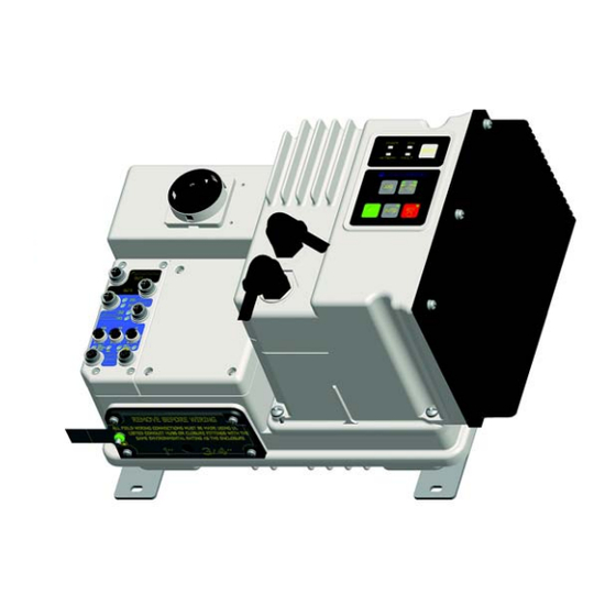
ArmorStart Bulletin 280E: Full Voltage Starter Overview of the ArmorStart Bulletin 280E Demo Unit Control via RSLogix™ 5000 This section shows the user how to control the ArmorStart EtherNet/IP unit using Ladder Logic in RSLogix 5000. This method of control occurs over the Ladder Logic EtherNet network using a Programmable Logic Controller (PLC). - Page 32 Rung 1 will be used later and will be left as is. a. Select the Photo Sensor tag for the input rung element in Rung 0. Since the photo sensor is connected to Input 0 on the ArmorStart unit, the tag needed is the AS_EIP_280:I.In0 tag.
- Page 33 ArmorStart unit in the General tab of the ArmorStart Bulletin 280E Properties menu. If the name given to the unit was "ArmorStart", then all the tags in the figure above would have "ArmorStart" as the prefix to the tag names.
- Page 34 Enter. iii. You have now set one of the outputs to be the Run Forward command that energizes the output of the ArmorStart Bulletin 280E. The ladder logic element should look like the figure below. Rockwell Automation Publication 280E-PM001A-EN-P – August 2011...
- Page 35 Select the signal light as the other output ladder element that turns on when you wave your hand in front of the photo sensor. Since the signal light is connected to Output A of the ArmorStart unit, you are actually selecting the OutA tag.
- Page 36 “Offline”, to show the available controller options. Click on the Go Online option. b. You may see a screen pop up that is similar to the figure below. Click on Download to download the program to the controller. Rockwell Automation Publication 280E-PM001A-EN-P – August 2011...
- Page 37 8. You have just added a few different tag names from different elements of the system, downloaded the ladder logic program to the controller, and now have the ArmorStart Bulletin 280E unit up and running. Wave your hand in front of the photo sensor, you should see the signal light turn on and also hear the output contactor close.
-
Page 38: Configuring The Armorstart Using The Parameter List In
1. Before accessing the ArmorStart's parameters, bring the unit Online. Refer to Step 7 on page if needed. 2. To access the parameter list, bring up the ArmorStart Bulletin 280E Properties menu by double clicking on the ArmorStart Bulletin 280E element in the I/O configuration tree. - Page 39 5. The following screen will pop up. This screen is confirming that you want to reset the parameters within the ArmorStart unit. Click Yes to continue. 6. This screen will pop up letting you know that the parameters have been reset to their default values.
- Page 40 Properties menu. Refer to the figure below. 9. The following screen should appear, click Yes to confirm updating the parameters in the ArmorStart unit. Rockwell Automation Publication 280E-PM001A-EN-P – August 2011...
-
Page 41: Hand/Off/Auto (Hoa) Control
11. Click OK at the bottom of the Properties menu to exit the menu. Hand/Off/Auto (HOA) This section focuses on controlling the ArmorStart EtherNet/IP unit using the Hand/Off/Auto (HOA) keypad. The HOA keypad allows the user to switch Control... - Page 42 ArmorStart EtherNet/IP Communications & Control Programming Manual 2. With the ArmorStart Bulletin 280E properly configured, the unit should be in Auto control mode and controlled via the EtherNet/IP communications. 3. To change control from Auto control mode to Hand/manual control mode, first press the Off button.
-
Page 43: Diagnostics And Faults
LED indicator represents. The Fault LED has various blink patterns to inform the user what type of fault occurred. For Fault LED blink patterns and other diagnostic and fault information, reference Appendix Rockwell Automation Publication 280E-PM001A-EN-P – August 2011... - Page 44 2. Turn the A3 Fault switch, wait for 3 seconds, and then let go of the switch so it can return to the closed position. a. A few seconds after the A3 power has been restored, the ArmorStart unit should display its fault status information.
- Page 45 71. d. Compare the bits of AS_EIP_280:I.Int01DeviceOut to the Trip Status definition in the Bulletin 280E Trip Status section on page 71. Verify the reported fault matches the fault that was created. Rockwell Automation Publication 280E-PM001A-EN-P – August 2011...
- Page 46 EtherNet/IP connection, is to click on the Reset Fault button on the AOP. See the figure below. 9. Once you are done with this section, reset the ArmorStart Bulletin 280E to the default settings. This is done by going online and clicking the Reset Defaults button.
-
Page 47: Control Via Rslogix 5000 Ladder Logic
Run Forward command from the ArmorStart unit to the load. Rung 1 uses an input bit to issue a Run Reverse command from the ArmorStart unit to the load. Similarly, the Jog Forward and Jog Reverse commands in Rungs 2 and 3 will issue jog forward and jog reverse commands from the ArmorStart unit to the load. - Page 48 2, and 4. Rungs 1, 3, and 5 will be left as is. a. Select the photo sensor tag for the input rung element in Rung 0. Since the photo sensor is connected to Input 0 on the ArmorStart unit, the tag needed is the AS_EIP_284:I.In0 tag.
- Page 49 Chapter 5 unit in the General tab of the ArmorStart Bulletin 284E Properties menu. If the name given to the unit was "ArmorStart", then all the tags in the figure above would have "ArmorStart" as the prefix to the tag names.
- Page 50 Rung 2 and click on the drop-down arrow to show the available tag options for this element. ii. Expand the options for the AS_EIP_284:O by clicking on the plus next to AS_EIP_284:O. Select AS_EIP_284:O.JogForward tag name and hit Enter. Rockwell Automation Publication 280E-PM001A-EN-P – August 2011...
- Page 51 Select the signal light as the output ladder element for Rung 4. Since the signal light is connected to Output A of the ArmorStart unit, you are actually selecting the OutA tag.
- Page 52 AS_EIP_284:O. Select AS_EIP_284:O.OutA tag name and hit Enter. iii. The output of Rung 4 is now set to be Output A that turns on the signal light. The ladder logic element should look like the figure below. Rockwell Automation Publication 280E-PM001A-EN-P – August 2011...
- Page 53 7. Bring the controller online. a. Click on the Controller icon in the upper left hand corner of the screen next to the word Offline to show the available controller options. Click on the Go Online option. Rockwell Automation Publication 280E-PM001A-EN-P – August 2011...
- Page 54 The upper left hand corner of your screen should now match the figure below. The controller is in remote run mode. The I/O Not Responding indicator should be blinking green since the RSLogix 5000 program was written to accommodate both the Rockwell Automation Publication 280E-PM001A-EN-P – August 2011...
- Page 55 8. You have just added a few different tag names from different elements of the system, downloaded the ladder logic program to the controller, and now have the ArmorStart Bulletin 284E unit up and running. a. Wave your hand in front of the photo sensor, you should see the small AC induction motor in the demo unit start to accelerate forward and the signal light turn on.
-
Page 56: Configuring The Armorstart Using The Parameter List In
1. Before accessing the ArmorStart's parameters, bring the unit Online. Refer to Step 7 on page if needed. 2. To access the parameter list, bring up the ArmorStart Bulletin 284E Properties menu by double clicking on the ArmorStart Bulletin 284E element in the I/O configuration tree. - Page 57 4. Reset the unit back to the factory default values by clicking on the Reset Defaults button. 5. The following screen will pop up. This screen is confirming that you want to reset the parameters within the ArmorStart unit. Click Yes to continue. Rockwell Automation Publication 280E-PM001A-EN-P – August 2011...
- Page 58 138 to Preset Freq. Reference parameters 170…177 to view the preset frequency values. j. Parameter 139 sets the rate of acceleration for all speed increases by setting the acceleration time in seconds. Set parameter 139 to 15 seconds. Rockwell Automation Publication 280E-PM001A-EN-P – August 2011...
- Page 59 9. Attempt to enter a parameter value that is outside the allowed range by setting parameter 131 to 600. The following warning screen should appear. Click OK to clear this screen and return to the Parameters menu to set the parameter within the allowed range. Rockwell Automation Publication 280E-PM001A-EN-P – August 2011...
-
Page 60: Hand/Off/Auto (Hoa) Control
Auto control mode and controlled via the EtherNet/IP communications. 3. To gain manual control of the ArmorStart Bulletin 284E, first take the unit out of auto control mode by pushing the Off button. Rockwell Automation Publication 280E-PM001A-EN-P – August 2011... - Page 61 Press the Jog button to see the Bulletin 284E unit jog the motor in the direction designated by the Forward/Reverse button. Rockwell Automation Publication 280E-PM001A-EN-P – August 2011...
- Page 62 46 to Disabled and click the Set button. Click the OK button to exit the Properties menu. 12. Attempt to manually control the unit using the HOA keypad. Verify that the HOA keypad has been disabled. Rockwell Automation Publication 280E-PM001A-EN-P – August 2011...
-
Page 63: Diagnostics And Faults
Fault This LED is used to indicate the fault status of the ArmorStart. When the unit is faulted, the unit will respond with a specific blink pattern to identify the fault. Note: Verify that the A3 Power Loss fault is enabled within parameter 24, Pr Fault Enable, before starting this section. -
Page 64: Rockwell Automation Publication 280E-Pm001A-En-P – August
AS_EIP_284:I.Int01DeviceOut to see the individual bits of this word. AS_EIP_284:I.Int01DeviceOut points to parameter 4 which is Trip Status. These 16 bits correlate to the Trip Status bit descriptions in the Bulletin 284E Trip Status section on page 72. Rockwell Automation Publication 280E-PM001A-EN-P – August 2011... - Page 65 EtherNet/IP connection, is to click on the Reset Fault button on the AOP. See the figure below. 9. Once you are done with this section, reset the ArmorStart Bulletin 284E to the default settings. This is done by clicking on the Reset Defaults button.
- Page 66 ® ™ Chapter 5 ArmorStart EtherNet/IP Communications & Control Programming Manual Notes: Rockwell Automation Publication 280E-PM001A-EN-P – August 2011...
- Page 67 I/O Fault This error can indicate a shorted sensor, shorted input device, or input wiring mistakes It can also indicate a blown output fuse. This fault can be disabled and is disabled by default. Rockwell Automation Publication 280E-PM001A-EN-P – August 2011...
- Page 68 DC Bus Fault Indicates the drive has detected a DC Bus Fault. This fault cannot be disabled. EEPROM Fault This is a major fault, which renders the ArmorStart inoperable. This fault cannot be disabled. Hardware Fault Indicates incorrect base/starter assembly. This fault cannot be disabled.
-
Page 69: Bulletin 280E Blink Patterns
— Reserved Not Used — Reserved Not Used Drive Control Pwr Loss The ArmorStart has detected a loss of the Controlled (Switched Power) control power voltage. Drive Input Fault This error indicates a shorted sensor, shorted Controlled input device, wiring input mistakes, or a blown output fuse. -
Page 70: Bulletin 284E Blink Patterns
Drive Stall Drive is unable to accelerate motor. Controlled (Drive Code 6) Parameter 23 Control Pwr Loss The ArmorStart has detected a loss of the (PrFlt Reset (Switched Power) control power voltage. Mode) Parameter 23 Input Fault This error indicates a shorted sensor, shorted... -
Page 71: Bulletin 280E Trip Status
Value of the parameter pointed to by "Parameter 16 Prod Assy Word 3" (high byte) Trip Status Parameter Number Access Rule This parameter provides trip identification. Data Type WORD Group Basic Status Units — Minimum Value Maximum Value 16383 Default Value Rockwell Automation Publication 280E-PM001A-EN-P – August 2011... -
Page 72: Bulletin 284E Trip Status
Net Out 9 Value of the parameter pointed to by "Parameter 13 Prod Assy Word 0" (low byte) Value of the parameter pointed to by "Parameter 13 Prod Assy Word 0" (high byte) Rockwell Automation Publication 280E-PM001A-EN-P – August 2011... - Page 73 — — — — — — — — — — — — — — Restart Retries — — — — — — — — — — — — — — — Misc. Fault Rockwell Automation Publication 280E-PM001A-EN-P – August 2011...
-
Page 74: Ethernet/Ip Indicators
If the device has detected a non-recoverable major fault, the module status indicator shall be steady red, refer to Table 7. Flashing Green/Red Self-test While the device is performing its power up testing, the module status indicator shall be flashing green/red. Rockwell Automation Publication 280E-PM001A-EN-P – August 2011... - Page 75 Solid Red The device has detected a major error that has Troubleshooting should be done to ensure that rendered it incapable of working. the control module internal switch settings are correct. Consult factory. Rockwell Automation Publication 280E-PM001A-EN-P – August 2011...
- Page 76 ® ™ Appendix A ArmorStart EtherNet/IP Communications & Control Programming Manual Notes: Rockwell Automation Publication 280E-PM001A-EN-P – August 2011...
-
Page 77: Using The Bootp/Dhcp Server
Before using your ArmorStart in an EtherNet/IP network you may need to configure an IP address, subnet mask, and optional Gateway address. This will show you how to set up the IP Address of an ArmorStart in three different ways: using the BootP/DHCP Server, the Rotary Network Address Switches, and the internal web server. - Page 78 DHCP server. The DHCP server will also assign other Transport Control Protocol (TCP) parameters. If DHCP is not enabled, the adapter will use the IP address (along with other TCP configurable parameters) stored in nonvolatile memory. Rockwell Automation Publication 280E-PM001A-EN-P – August 2011...
-
Page 79: Using The Armorstart Internal Web Server
ArmorStart Ethernet/IP. The internal web server allows you to view information Internal Web Server and configure the ArmorStart via a web browser. The internal web server can be used to set up the ArmorStart IP address by performing the following this steps: 1. - Page 80 Name and a Password is displayed. Enter the pre-set User Name and Password or if they have not been set up previously, use the default User Name and Password. The default User Name is Administrator and there is no password set by default. Rockwell Automation Publication 280E-PM001A-EN-P – August 2011...
- Page 81 From this screen you are able to change the Ethernet Configuration. For example, the default IP address shown is changed from 192.168.1.1 to 10.10.10.101. After a power cycle the new address must be used to access the web page. Rockwell Automation Publication 280E-PM001A-EN-P – August 2011...
- Page 82 ® ™ Appendix B ArmorStart EtherNet/IP Communications & Control Programming Manual Notes: Rockwell Automation Publication 280E-PM001A-EN-P – August 2011...
- Page 83 A Type 1 Reset will be sent to the product’s identity object. This reset will place the ArmorStart in an "Out of the Box" configuration (except for those with IP addresses that are statically configured). The controller will then performs a power cycle.
- Page 84 Reset of the type BOOL (Boolean). 6. Create a rung in ladder logic for executing the Type 1 Reset. a. Add an XIC Input and assign it the BOOL tag Reset. Rockwell Automation Publication 280E-PM001A-EN-P – August 2011...
- Page 85 The completed rung should look like the one below. 7. Configure the message instruction: a. Begin by double clicking on the tag name field and entering AS_Reset. b. Right click on the tag name AS_Reset and select New "AS_Reset". Rockwell Automation Publication 280E-PM001A-EN-P – August 2011...
- Page 86 Bring up the Configuration Dialog screen by clicking the box next to the tag name AS_Reset. e. Select CIP Generic from the Message Type drop-down menu and Custom from the Service Type drop-down menu. Rockwell Automation Publication 280E-PM001A-EN-P – August 2011...
- Page 87 Enter 5 for the Service Code, 1 for the Class, and 1 for the Instance. Leave the Attribute value at 0. Once you have added these values, the Service Type should automatically change to Device Reset. Rockwell Automation Publication 280E-PM001A-EN-P – August 2011...
- Page 88 Click on the Communication tab at the top of the window. Click on the Browse button, select the ArmorStart that is in your project, and click OK. This selects the ArmorStart as the device you are going to send the reset message to.
- Page 89 Click Apply, the following screen should pop-up. Click Yes. Then click OK to close out the AOP. c. You should see the yellow inhibit symbol next to the ArmorStart in the I/O Configuration tree showing that the module is inhibited.
- Page 90 ArmorStart, and ControlLogix are registered trademarks of Rockwell Automation, Inc. RSLogix 5000 is a trademark of Rockwell Automation, Inc. Ethernet/IP, is a trademarks of the Open Device Vendors Association (ODVA). Ethernet is a registered trademark of Digital Equipment Corporation, Intel, and Xerox Corporation.
Need help?
Do you have a question about the ARMORSTART and is the answer not in the manual?
Questions and answers